
8050B - Loudspeaker GENELEC - Free user manual and instructions
Find the device manual for free 8050B GENELEC in PDF.


| Product type | Bi-amplified active studio monitor |
| Brand | Genelec |
| Model | 8050B |
| Dimensions (H x W x D) | 410 x 256 x 344 mm (16.1 x 10.1 x 13.5 in) |
| Weight | 14 kg (30.9 lb) |
| Frequency response | 32 Hz – 25 kHz (-6 dB) |
| Maximum SPL | 110 dB peak at 1 m |
| Amplifier power | 160 W (LF) + 120 W (HF) |
| Drivers | 8" woofer + 1" metal dome tweeter |
| Input connector | XLR balanced (analog) |
| Input impedance | 10 kΩ balanced |
| Input sensitivity | -6 dBu to +6 dBu (adjustable) |
| Crossover frequency | 3 kHz (active) |
| Bass management | Room response controls (treble, bass, presence) |
| Power saving | Intelligent Signal Sensing (ISS) auto-standby |
| Power supply | 100–240 V AC, 50/60 Hz |
| Power consumption | Standby < 0.5 W, idle 15 W, max 200 W |
| Operating temperature | 0°C to 35°C (32°F to 95°F) |
| Mounting | Optional brackets or table stands |
| Safety | Overvoltage, overcurrent, thermal protection |
| Cleaning | Wipe with dry or slightly damp cloth; do not use solvents |
| Repairability | Genelec spare parts available; authorized service centers |
| Certification | CE, RoHS |
Frequently Asked Questions - 8050B GENELEC
User questions about 8050B GENELEC
0 question about this device. Answer the ones you know or ask your own.
Ask a new question about this device
Download the instructions for your Loudspeaker in PDF format for free! Find your manual 8050B - GENELEC and take your electronic device back in hand. On this page are published all the documents necessary for the use of your device. 8050B by GENELEC.
USER MANUAL 8050B GENELEC
Operating Manual 2-6
Käyttöohje 7-11
操作手册 12-16
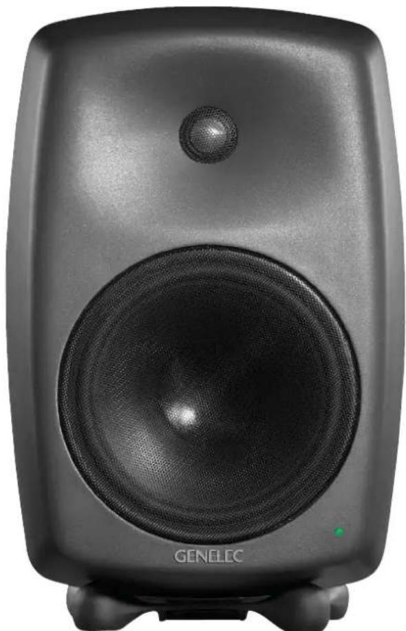
natural_image
Black studio album speaker with visible sound waves and a green indicator light (no text or symbols on the speaker body)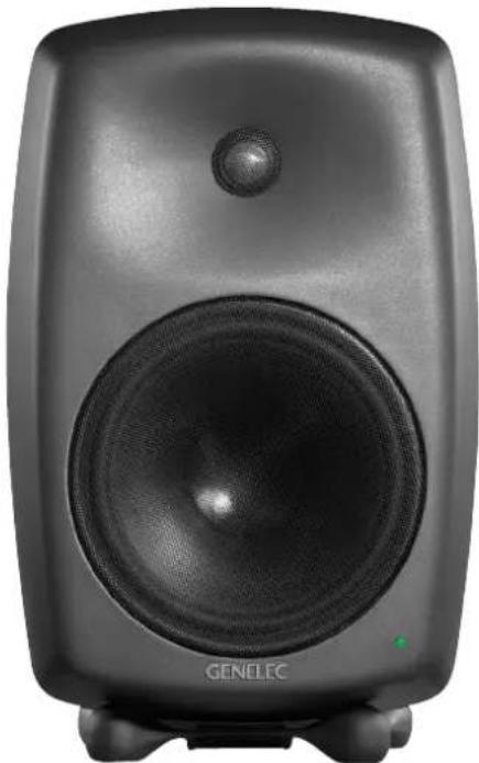
natural_image
Black studio album speaker with visible sound waves and a green logo (no text or symbols on the speaker body)Genelec 8040B and 8050B Active Monitoring Systems
System
The GENELEC 8040B and 8050B are two way active monitoring loudspeakers designed to produce high SPL output, low coloration and broad bandwidth in a small enclosure size. They are suitable for a wide variety of tasks, such as near field monitoring, mobile vans, broadcast and TV control rooms, surround sound systems and home studios. Designed as active loudspeakers, they contain drivers, power amplifiers, active crossover filters and protection circuitry. The Minimum Diffraction Enclosure™ (MDE™) and advanced Directivity Control Waveguide™ (DCW™) technologies provide excellent frequency balance even in difficult acoustic environments.
Drivers
The bass driver dimensions are 165 mm (6 1/2") and 205 mm (8") for 8040B and 8050B respectively. The long, flow optimized reflex tube has a large cross sectional area and terminates with a wide flare at the back of the enclosure. The high frequency driver is a 19 mm (3/4") metal dome on the 8040B and a 25 mm (1") metal dome on the 8050B. Both drivers are magnetically shielded.
Crossover
The active crossover network consists of two parallel bandpass filters. The crossover frequency is 3.0 kHz on the 8040B and 1.8 kHz on the 8050B. The active crossover controls ("treble tilt", "desktop low frequency", "bass tilt" and "bass roll-off") allow precise matching of the loudspeakers to any room environment.
Amplifiers
The amplifier unit is mounted in the rear of the loudspeaker enclosure. The unit incorporates special circuitry for driver thermal overload protection. Variable input sensitivity allows accurate level matching to console output section.
Connections
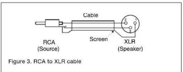
Each loudspeaker is supplied with a mains cable and an operating manual. Before connecting up, ensure that the mains switch is off (see figure 1). Audio input is via a 10 kOhm balanced XLR connector, but unbalanced leads may be used as long as pin 3 is grounded to pin 1 of the XLR (see figure 3). Once the connections have been made, the loudspeakers are ready to be switched on.
Mounting considerations Align the loudspeakers correctly
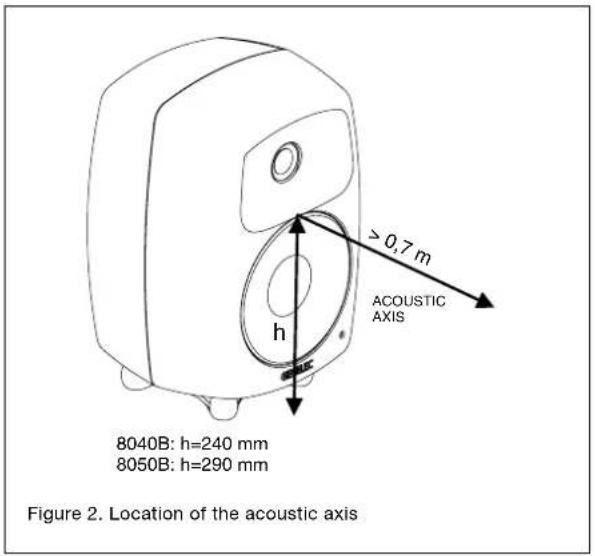
Always place the loudspeakers so that their acoustic axes (see figure 2) are aimed towards the listening position. Vertical placement is preferable, as it minimises acoustical cancellation problems around the crossover frequency.
Maintain symmetry
Check that the loudspeakers are placed symmetrically and at an equal distance from the listening position. If possible, place the system so that the listening position is on the centerline of the room and the loudspeakers are placed at an equal distance from the centerline.
Minimise reflections
Acoustic reflections from objects close to the loudspeakers like desks, cabinets, computer monitors etc. can cause unwanted colouration and blurring of the sound image. These can be minimised by placing the loudspeaker clear of reflective surfaces. For instance, putting the loudspeakers on stands behind and above the mixing console usually gives a better result than placing them on the meter bridge.

Minimum clearances
Sufficient cooling for the amplifier and functioning of the reflex port must be ensured if the loudspeaker is installed in a restricted space such as a cabinet, or integrated into a wall structure. The surroundings of the loudspeaker must always be open to the listening room with a minimum clearance of 5 centimeters (2") behind, above and on both sides of the loudspeaker. The space adjacent to the amplifier must either be ventilated or sufficiently large to dissipate heat so that the ambient temperature does not rise above 35 degrees Celsius (95°F).
Mounting options
The vibration insulating Isolation Positioner/Decoupler™ (Iso-Pod™) table stand allows tilting of the loudspeaker for correct alignment of the acoustic axis. The stand can be attached to three mounting points allowing vertical and symmetrical horizontal positioning (see figures 1 and 5).
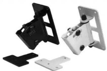
Genelec 8040B and 8050B can be fitted to Omnimount® Series 30 (8040B) and 60 (8050B) and König & Meyer loudspeaker mounts on two sets of M6x10 mm threaded holes on the back of the enclosure. On the base of the enclosure is an M10x10 mm threaded hole which can be used for securing the loudspeaker to its base. Do not use this thread for mounting the loudspeaker on a microphone stand which has a 3/8" UNC thread.
Setting the input sensitivity
The input sensitivity of the loudspeakers can be matched to the output of the mixing console, or other source, by adjusting the input sensitivity control on the rear panel (see figure 1). A screwdriver is needed for the adjustment. The manufacturer's default setting for this control is -6 dBu (fully clockwise) which gives an SPL of 100 dB @1m with -6 dBu input level.
ISS ^TM autostart function
When the power switch on the loudspeaker is set to "ON", the Intelligent Signal Sensing™ (ISS™) autostart function of the loudspeaker is active. Automatic powering down to standby mode happens after a certain time when playback has ended. The power consumption in standby mode is typically less than 0.5 watts. The playback will automatically resume once an input signal is detected from the source.
There is a slight delay in the automatic powering up. If this is undesirable, the ISS™ function can be disabled by setting the "ISS DISABLE" switch on the back panel to "ON" position. In this mode, the monitor is powered on and off using the power switch on the back panel.
Setting the tone controls
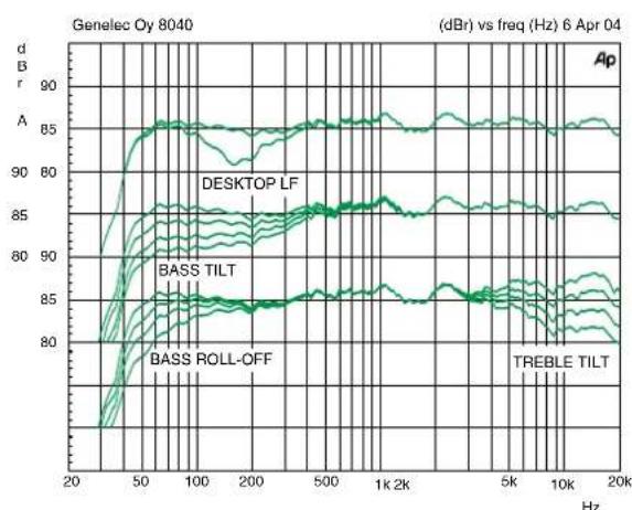
The frequency response of the system may also have to be adjusted to match the acoustic environment. The adjustment is carried out by setting the three tone control switch groups "treble tilt", "bass tilt" and "bass roll-off" on the rear panel of the amplifier. There is also a special "desktop low frequency" tone control which gives an attenuation of 4 dB at 160 Hz to compensate the effect of a mixing console, desk or other reflective surface between the listener and the loudspeaker. The factory settings for these controls are all "OFF" to give a flat anechoic response.
Bass roll-off control
Bass roll-off (first switch group from the left) affects the low frequency roll-off of the loudspeaker and attenuates its energy output near the cut-off frequency. Attenuation levels of -2, -4 or -6 dB can be selected.
| Speaker Mounting Position T | tleble tilt Bass | tilt Bass roll-off | Desktop LF | |
| Flat anechoic response None | None None None | |||
| Free standing in a damped room | None -2 dB | None None | ||
| Free standing in a reverberant room | None -4 dB | None None | ||
| Near field on a reflective surface | None -2 dB | None | -4 dB | |
| In a corner | None | -4 dB | -4 dB | None |
Table 1. Suggested tone control settings in some typical situations
natural_image
Disassembled mechanical bracket components, including black and white parts (no text or symbols visible)Figure 4. K&M type wall mount
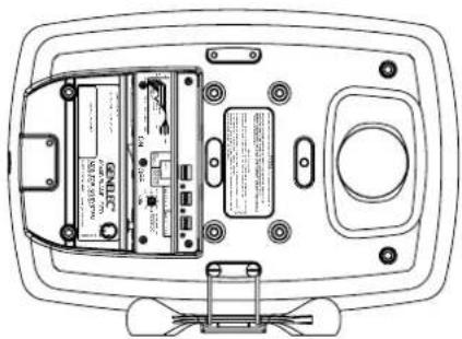
Figure 5. The Iso-Pod™ can also be attached to the side of the enclosure for horizontal mounting.
natural_image
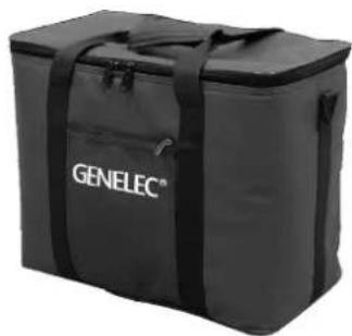
Black rectangular container with 'GENELEC®' branding, no visible text or symbols on the bodyFigure 6. Carrying bag for a pair of 8040B loudspeakers.
Desktop low frequency control
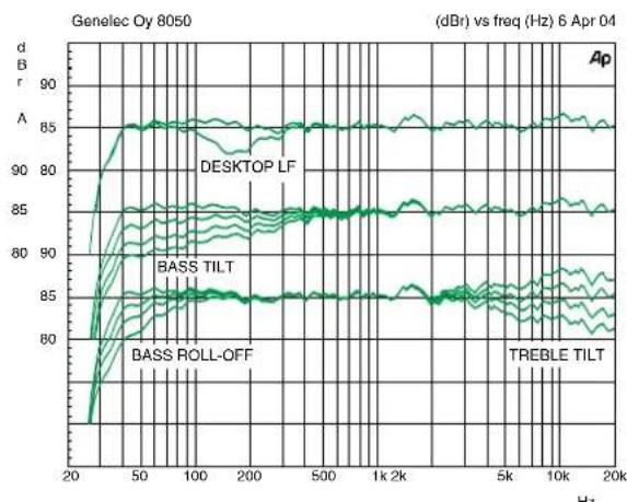
The desktop low frequency control (fifth switch of first switch group from the left) attenuates the bass frequencies around 160 Hz by 4 dB (see figures 7 and 9). This feature is designed to compensate for the boost often occurring at this frequency range when the loudspeaker is placed upon a meter bridge, table or similar reflective surface.
Bass tilt control
The bass tilt control switches (second switch group from the left) offer three attenuation levels for the bass response below 800 Hz, usually necessary when the loudspeakers are placed near room boundaries. The attenuation levels are -2 dB, -4 dB and -6 dB.
Treble tilt control
Treble tilt (third switch group from the left) allows adjusting the treble response above 5 kHz by +2, -2, or -4 dB, which can be used for correcting an excessively bright or dull sounding system.
An acoustic measuring system such as WinMLS is recommended for analyzing the effects of the adjustments, however, care-
ful listening with suitable test recordings can also lead to good results if a test system is not available. Table 1 shows some typical settings in various situations. Figures 7 and 9 show the effect of the controls on the anechoic response.
Always start adjustment by setting all switches to "OFF" position. Then set only one switch per group to the "ON" position to select the desired adjustment. If more than one switch is set to "ON" (within one switch group) the attenuation value is not accurate.
Measure or listen systematically through the different combinations of settings to find the best frequency balance.
Maintenance
No user serviceable parts are to be found within the loudspeaker cabinet or the amplifier unit. Any maintenance or repair of the loudspeaker should only be undertaken by qualified service personnel.
Safety considerations
Although the 8040B and 8050B have been designed in accordance with international safety standards, to ensure safe operation and to maintain the loudspeaker under safe operating conditions, the following warnings and cautions must be observed:
• Servicing and adjustment must only be performed by qualified service personnel. The loudspeaker must not be opened.
- Do not use this product with an unearthed mains cable as this may lead to personal injury.
• To prevent fire or electric shock, do not expose the unit to water or moisture. Do not place any objects filled with liquid, such as vases on the loudspeaker or near it.
• Note that the amplifier is not completely disconnected from the AC mains service unless the mains power cord is removed from the amplifier or the mains outlet.
• Free flow of air behind the loudspeaker is necessary to maintain sufficient cooling. Do not obstruct airflow around the loudspeakers.
- Do not expose the loudspeaker to water or moisture. Do not place any objects filled with liquid, such as vases on the loudspeaker or near it.
WARNING!
Genelec 8040B and 8050B loudspeakers are capable of producing sound pressure levels in excess of 85 dB, which may cause permanent hearing damage.
line
| Frequency (Hz) | Desktop LF | Bass TILT | Bass Roll-Off | TREBLE TILT | | -------------- | ---------- | --------- | ------------- | ----------- | | 20 | ~85 | ~85 | ~85 | ~85 | | 50 | ~86 | ~86 | ~86 | ~86 | | 100 | ~87 | ~87 | ~87 | ~87 | | 200 | ~87 | ~87 | ~87 | ~87 | | 500 | ~87 | ~87 | ~87 | ~87 | | 1k | ~87 | ~87 | ~87 | ~87 | | 2k | ~87 | ~87 | ~87 | ~87 | | 5k | ~87 | ~87 | ~87 | ~87 | | 10k | ~87 | ~87 | ~87 | ~87 | | 20k | ~87 | ~87 | ~87 | ~87 |Figure 7. The curves above show the effect of the "bass tilt", "treble tilt", "desktop low frequency" and "bass roll-off" controls on the free field response of the 8040B.
line
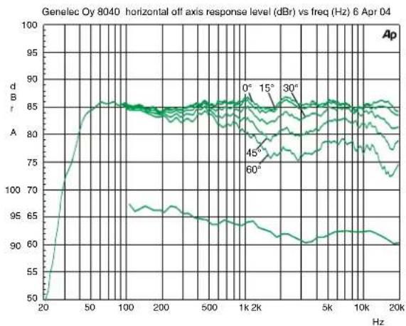
| Frequency (Hz) | dA (dBm) | | -------------- | -------- | | 20 | 50 | | 50 | 85 | | 100 | 85 | | 200 | 85 | | 500 | 85 | | 1k | 85 | | 2k | 85 | | 5k | 85 | | 10k | 85 | | 20k | 85 |Figure 8. The upper curve group shows the horizontal directivity characteristics of the 8040B measured at 1 m. The lower curve shows the system's power response.
line
| Frequency (Hz) | DESKTOP LF | BASS TILT | BASS ROLL-OFF | TREBLE TILT | | -------------- | ---------- | --------- | ------------- | ----------- | | 20 | ~85 | ~85 | ~85 | ~85 | | 50 | ~85 | ~85 | ~85 | ~85 | | 100 | ~85 | ~85 | ~85 | ~85 | | 200 | ~85 | ~85 | ~85 | ~85 | | 500 | ~85 | ~85 | ~85 | ~85 | | 1k | ~85 | ~85 | ~85 | ~85 | | 2k | ~85 | ~85 | ~85 | ~85 | | 5k | ~85 | ~85 | ~85 | ~85 | | 10k | ~85 | ~85 | ~85 | ~85 | | 20k | ~85 | ~85 | ~85 | ~85 |Figure 9. The curves above show the effect of the "bass tilt", "treble tilt", "desktop low frequency" and "bass roll-off" controls on the free field response of the 8050B
line
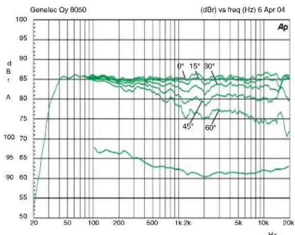
| Frequency (Hz) | Amplitude (dB) | | -------------- | -------------- | | 20 | ~50 | | 50 | ~85 | | 100 | ~85 | | 200 | ~85 | | 500 | ~85 | | 1k | ~85 | | 2k | ~85 | | 5k | ~85 | | 10k | ~85 | | 20k | ~85 |Figure 10. The upper curve group shows the horizontal directivity characteristics of the 8050B measured at 1 m. The lower curve shows the system's power response.
Guarantee
Genelec 8040B and 8050B are supplied with two year guarantee against manufacturing faults or defects that might alter the performance of the loudspeakers. Refer to supplier for full sales and guarantee terms.
Compliance to FCC rules
This device complies with part 15 of the FCC Rules. Operation is subject to the following two conditions:
• This device may not cause harmful interference
- This device must accept any interference received, including interference that may cause undesired operation.
Note: This equipment has been tested and found to comply with the limits for a Class B digital device, pursuant to part 15 of the FCC Rules. These limits are designed to provide reasonable protection against harmful interference in a residential installation. This equipment generates, uses and can radiate radio frequency energy and, if not installed and used in accordance with the instructions, may cause harmful interference to radio communications. However, there is no guarantee that interference will not occur in a particular installation. If this equipment does cause harmful interference to radio or television reception, which can be determined by turning the equipment off and on, the user is encouraged to try to correct the interference by one or more of the following measures:
- Reorient or relocate the receiving antenna. Increase the separation between the equipment and receiver.
- Connect the equipment into an outlet on a circuit different from that to which the receiver is connected.
- Consult the dealer or an experienced radio/TV technician for help
Modifications not expressly approved by the manufacturer could void the user's authority to operate the equipment under FCC rules.
| 8040B 8050B | ||
| Lower cut-off frequency, -3 dBUpper cut-off frequency, -3 dB | ≤ 45 Hz≥ 21 kHz | ≤ 35 Hz≥ 21 kHz |
| Free field frequency response of system (± 2.0 dB) | 48 Hz - 20 kHz 38 Hz | - 20 kHz |
| Maximum short term sine wave acoustic output on axis in half space, averaged from 100 Hz to 3 kHz@ 1 m@ 0.5 m | ≥ 105 dB SPL≥ 111 dB SPL | ≥ 110 dB SPL≥ 116 dB SPL |
| Maximum long term RMS acoustic output in same conditions with IEC weighted noise (limited by driver unit protection circuit) @ 1 m | ≥ 99 dB SPL ≥ 101 dB SPL | |
| Maximum peak acoustic output per pair above console top, @ 1 m distance with music material | ≥ 115 dB SPL ≥ 120 dB SPL | |
| Self generated noise level in free field @ 1m on axis (A-weighted) | ≤ 10 dB ≤ 10 dB | |
| Harmonic distortion at 90 dB SPL @ 1m on axisFreq. 50 to 100 Hz> 100 Hz | < 2 %< 0.5 % | < 2 %< 0.5 % |
| Drivers:BassTrebleBoth drivers are magnetically shielded | 165 mm ( 6^1/_2 in)19 mm ( ^3/_4 in)metal dome | 205 mm (8 in)25 mm (1 in)metal dome |
| Weight: 8.6 kg (18.9 lbs) 14.4 kg (3 | 1.7 lbs) | |
| Dimensions:Height (without table supportHeight (including table support)WidthDepth | 350 mm ( 13^13/_16 in)365 mm ( 14^3/_8 in)237 mm ( 9^3/_8 in)223 mm ( 8^13/_16 in) | 433 mm ( 17^1/_16 in)452 mm ( 17^13/_16 in)286 mm ( 11^1/_4 in)278 mm ( 10^15/_16 in) |
| croSSover SecTloNSySTeM SPeciFlcATIoNS | ||
| 8040B 8050B | ||
| Input connector XLR female Pin 1 grid, pin 2 +, pin 3 - | ||
| Input impedance 10 kOhm balanced | ||
| Input level for maximum short term output of 100 dB SPL @ 1m: | Adjustable from +6 to -6 dBu | |
| Crossover frequency, Bass/Treble 3 | 0 kHz | 18 kHz |
| Treble tilt control operating range in 2 dB steps | From +2 to -4 dB & MUTE @ 15 kHz | From +2 to -4 dB & MUTE @ 15 kHz |
| Desktop low frequency control operating range | -4 dB @ 160 Hz | -4 dB @ 160 Hz |
| Bass roll-off control operating range in 2 dB steps | From 0 to -6 dB @ 45 Hz | From 0 to -6 dB @ 35 Hz |
| Bass tilt control operating range in 2 dB steps | From 0 to -6 dB @ 100 Hz & MUTE | From 0 to -6 dB @ 100 Hz & MUTE |
| The 'CAL' position is with all tone controls set to 'off' and the input sensitivity control to maximum (fully clockwise) | ||
| AMPLIFIER SecTIoN | ||
| 8040B 8050B | ||
| Bass amplifier short term output power | 90 W | 150 W |
| 90 W | 120 W | |
| Treble amplifier short term output power | ||
| Long term output power is limited by driver unit protection circuitry | ||
| Amplifier system distortion at nominal output | ||
| THD | ≤ 0.05 % | ≤ 0.05 % |
| SMPTE-IM | ≤ 0.05 % | ≤ 0.05 % |
| CCIF-IM | ≤ 0.05 % | ≤ 0.05 % |
| DIM 100 | ≤ 0.05 % | ≤ 0.05 % |
| Signal to Noise ratio, referred to full output | ||
| Bass | ≥100 dB | ≥100 dB |
| Treble | ≥100 dB | ≥100 dB |
| Mains voltage 100, 120, 220 or 230 / according to region | ||
| Voltage operating range ±10 % ±10 % | ||
| Power consumption | ||
| Idle | 10 W | 10 W |
| Standby | < 0.5 W | <0.5 W |
| Full output | 110 W | 170 W |
natural_image
Top-down view of a black studio vinyl audio amplifier with a speaker grille and 'GENELEC' logo (no text-heavy elements)Genelec 8040B- ja 8050B-aktiivikaiuttimet
Yleistä
natural_image
Disassembled electronic components with black and white parts, no visible text or symbols on the parts themselves.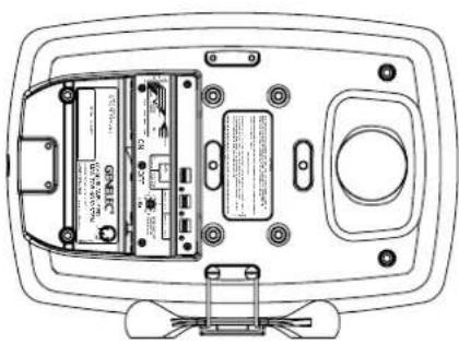
natural_image
Top-down schematic of a device rear panel showing internal components and connectors (no text or labels)natural_image
Black rectangular container with 'GENELEC' branding, no visible text or symbols on the bodyDesktop low frequency
line
| Frequency (Hz) | Desktop LF | Bass TILT | BASS ROLL-OFF | TREBLE TILT | | -------------- | ---------- | --------- | ------------- | ----------- | | 20 | ~85 | ~85 | ~85 | ~85 | | 50 | ~86 | ~86 | ~86 | ~86 | | 100 | ~86 | ~86 | ~86 | ~86 | | 200 | ~86 | ~86 | ~86 | ~86 | | 500 | ~86 | ~86 | ~86 | ~86 | | 1k | ~86 | ~86 | ~86 | ~86 | | 2k | ~86 | ~86 | ~86 | ~86 | | 5k | ~86 | ~86 | ~86 | ~86 | | 10k | ~86 | ~86 | ~86 | ~86 | | 20k | ~86 | ~86 | ~86 | ~86 |natural_image
Black studio album speaker with visible sound waves and a green logo (no text or symbols on the speaker body)图3. RCA转接线
最小间距
natural_image
Disassembled K&M wall frame components (no text or symbols visible)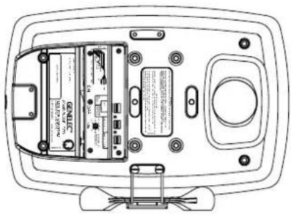
natural_image
Top-down schematic of a device rear panel with internal components and connectors (no text or labels)natural_image
Black and white photo of a black rectangular container with 'GENELEC' branding on the front face (no additional text or symbols visible)图6 8040B音箱便携包
Genelec Document D00SR001e Copyright Genelec Cy 9.2015. All data subject to change without prior notice.
www.genelec.com
GENELEC®
International enquiries:
Genelec. Ovitle 5
FIN-74100, lisalmi, Finland
Phone +358 17 83881
Fax +358 17 812 267
Email genelec@genelec.com
In the U.S. please contact:
Genelec, Inc., 7 Tech Circle
Natick, MA 01760, USA
In Sweden please contact:
Genelec Sverige
Ellipsvägen 10B
P.O. Box 5521, S-141 05 Huddinge
Phone +46 8 449 5220
Fax +46 8 708 7071
Email info@geneles.com
真力中国
北京市朝阳区酒仙桥路10号
恒通商务园 B33-101
电话4007001978
微信真力GENELEC
微博真力GENELEC
Email genelec.china@genelec.com
- Genelec 8040B and 8050B Active Monitoring Systems
- System
- Drivers
- Crossover
- Amplifiers
- Connections
- Mounting considerations Align the loudspeakers correctly
- Maintain symmetry
- Minimise reflections
- Minimum clearances
- Mounting options
- Setting the input sensitivity
- ISS TM autostart function
- Setting the tone controls
- Bass roll-off control
- Desktop low frequency control
- Bass tilt control
- Treble tilt control
- Maintenance
- Safety considerations
- WARNING!
- Guarantee
- Compliance to FCC rules
- Genelec 8040B- ja 8050B-aktiivikaiuttimet
- Yleistä
- Desktop low frequency
- 最小间距
Brand : GENELEC
Model : 8050B
Category : Loudspeaker