IC408A-R2 - Wi-Fi repeater Black Box - Free user manual and instructions
Find the device manual for free IC408A-R2 Black Box in PDF.


| Product Type | Wi-Fi Repeater |
| Brand | Black Box |
| Model | IC408A-R2 |
| Dimensions (W x D x H) | 110 x 70 x 35 mm |
| Weight | 150 g |
| Power Supply | DC 5V / 1A (USB cable included) |
| Wi-Fi Standards | IEEE 802.11 b/g/n |
| Frequency Band | 2.4 GHz |
| Maximum Data Rate | 300 Mbps |
| Wireless Security | WEP, WPA, WPA2 |
| Number of Antennas | 2 external antennas (5 dBi each) |
| Ethernet Port | 1 x 10/100 Mbps LAN |
| LED Indicators | Power, WAN, WLAN, LAN |
| Operation Modes | Repeater, Access Point |
| Setup Method | WPS button or web interface |
| Operating Temperature | 0°C to 40°C |
| Storage Temperature | -20°C to 70°C |
| Humidity | 10% to 90% non-condensing |
| Certifications | CE, FCC, RoHS |
| Package Contents | Repeater, USB cable, network cable, quick start guide |
| Warranty | 2 years |
| Cleaning | Wipe with a dry, soft cloth. Do not use liquids or solvents. |
| Safety | Do not expose to water or moisture. Keep away from heat sources. |
| Repairability | No user-serviceable parts. Contact support for repairs. |
Frequently Asked Questions - IC408A-R2 Black Box
User questions about IC408A-R2 Black Box
0 question about this device. Answer the ones you know or ask your own.
Ask a new question about this device
Download the instructions for your Wi-Fi repeater in PDF format for free! Find your manual IC408A-R2 - Black Box and take your electronic device back in hand. On this page are published all the documents necessary for the use of your device. IC408A-R2 by Black Box.
USER MANUAL IC408A-R2 Black Box
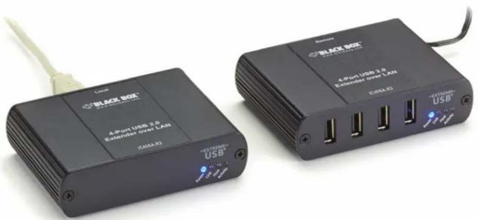
4-Port USB 2.0 Extender over LAN
Easily extend USB 2.0 signals over an IP network or directly over a CATx link.
natural_image
Two black USB devices with visible ports and labels, one labeled 'BLACK BOX' and the other '4-Port USB 2.0 Extender over LAN', connected by a white cable (no readable text beyond branding)Trademarks Used in this Manual
Black Box and the Double Diamond logo are registered trademarks of BB Technologies, Inc.
Mac and OS X are registered trademarks of Apple Computer, Inc.
Intel is a registered trademark of Intel Corporation.
Windows is a registered trademark of Microsoft Corporation.
Linux is a registered trademark of Linus Torvalds.
Any other trademarks mentioned in this manual are acknowledged to be the property of their respective owners.
Federal Communications Commission and Industry Canada Radio Frequency Interference Statements
This equipment generates, uses, and can radiate radio-frequency energy, and if not installed and used properly, that is, in strict accordance with the manufacturer's instructions, may cause interference to radio communication. It has been tested and found to comply with the limits for a Class A computing device in accordance with the specifications in Subpart B of Part 15 of FCC rules, which are designed to provide reasonable protection against such interference when the equipment is operated in a commercial environment. Operation of this equipment in a residential area is likely to cause interference, in which case the user at his own expense will be required to take whatever measures may be necessary to correct the interference.
Changes or modifications not expressly approved by the party responsible for compliance could void the user's authority to operate the equipment.
This digital apparatus does not exceed the Class A limits for radio noise emission from digital apparatus set out in the Radio Interference Regulation of Industry Canada.
2.1 Introduction 6
2.2 Features....6
2.3 What's Included 6
2.4 Hardware Description....7
2.4.1 Local Extender 7
2.4.2 Remote Extender 8
- Installation 9
3.1 Installing the IC408A-R2 on a Local Area Network....9
3.1.1 Requirements....9
3.1.2 Preparing Your Network....9
3.1.3 Preparing Your Site 10
3.1.4 Installing the Local Extender 10
3.1.5 Installing the Remote Extender....10
3.2 Installing the IC408A-R2 as Direct Connect....10
3.2.1 Requirements.... 10
3.2.2 Preparing Your Site 11
3.2.3 Installing the Local Extender 11
3.2.4 Connecting the Local Extender to the Remote Extender 11
3.2.5 Installing the Remote Extender 11
3.3 Checking the Installation....12
3.4 Connecting a USB Device....13
3.5 Pairing the Local and Remote Extender....13
3.6 Unpairing an Extender....13
3.7 Compatibility 13
- USB Extender Mounting Options 14
4.1 Option 1: USB Extender Mounting Kit .... 14
4.2 Option 2: USN Extender Direct Surface Mounting 15
- Troubleshooting....16
5.1 Troubleshooting Tips....16
5.2 Contacting Black Box 18
5.3 Shipping and Packaging....18
-
Technical Glossary....19
-
Specifications
| Approvals Regulatory testing: | FCC (Class B), CE (Class B), RoHS2 (CE); |
| Networking Standards: 1000BASE-T* | * Maximum speed is heavily dependant on network configuration, bandwidth and performance.1000BASE-T is highly recommended for best performance.Data Traffic: Layer 2;Control Traffic: Layer 3, customizable as unicast or broadcast |
| Distance | Direct connect: Up to 328 feet (100 m) over solid-core CAT5e/6/7 cable;Network connect: Up to 328 feet (100 m) over solid-core CAT5e/6/7 cable |
| Maximum USB Devices Supported Up to 30 devices | |
| USB Device Support High-speed devices | (480 Mbps, USB 2.0);Full-speed devices (12 Mbps, USB 2.0 and 1.1);Low-speed devices (1.5 Mbps, USB 2.0 and 1.1) |
| Enclosure Material Black anodized aluminum | |
| Connectors Local unit: | (1) USB Type B, (1) RJ-45;Remote unit:(4) USB Type A, (1) RJ-45 |
| Temperature Tolerance Operating: | 32 to 122°F (0 to 50°C);Storage:-4 to 158°F (-20 to 70°C) |
| Humidity Tolerance | Operating:20 to 80% relative humidity, non-condensing;Storage:10 to 90% relative humidity, non-condensing |
| Power | NOTE: One power supply is included for remote unit. Local unit derives power from the USB interface.Input:100/240 VAC, 50–60 Hz;Output:24 VDC, 1 A;AC adapter connector:2.1-mm center positive jackPower available to USB device at remote unit:Up to 2.4 A total among the ports, but 1 A max. per port;Power consumption:Local unit:200 mA maximum,Remote unit:Up to 2.4 A total among the ports, but 1 A max. per port |
| Dimensions | Each unit: 3.9"H x 3"W x 1"D (9.9 x 7.6 x 2.5 cm) |
| Weight | Shipping: 2.2 lb. (1 kg) |
2. Overview
2.1 Introduction
Extend USB signals for up to four devices as far as 328 feet (100 m) over a non-networked CAT5e connection or over your Ethernet LAN. The 4-Port USB 2.0 Extender over LAN uses inexpensive UTP cable you may already have installed in your building or your existing LAN architecture for easy, cost-effective USB extension. It's ideal for USB keyboard and mouse extension and sensor/data acquisition applications. Plus, it's great for connecting to whiteboards in classrooms located beyond the maximum USB bus distance. Or use the extender to bridge the gap between a computer CPU or server and USB flash drives, scanners, and printers in other rooms, as well as for connecting USB monitoring cameras or USB touchscreens used for interactive digital signage.
The extender offers reliable operation with all USB 2.0 and 1.1 peripheral devices, including USB hubs. The local unit is powered from the USB interface. The remote unit receives its power from the included AC adapter, and supplies up to 1 A to each port.
2.2 Features
- Includes a local unit and remote unit with four USB 2.0 ports.
- Enables easy switching of local and remote extender pairs.
- Supports multiple 1:1 networked configurations.
- Extends USB signals up to 480 Mbps.
- Remote unit supplies up to 1 A power to each port concurrently.
- Plug-and-play. No drivers to install on your computer.
- Works with Windows®, Mac® OS X®, and Linux® systems.
2.3 What's Included
Your package should include the following items. If anything is missing or damaged, contact Black Box Technical Support at 877-877-2269 or info@blackbox.com.
• (1) Local Extender Unit
• (1) Remote Extender Unit
• (1) USB 2.0 cable
• (1) Remote Extender AC international power adapter
• (1) power cable
- Quick start guide
To download this user manual:
- Go to www.blackbox.com
- Enter the part number in the search box.
- Click on the product in the "Product Results" page.
- Click on the "Support" tab on the product page, and select the document you wish to download.
If you have any trouble accessing the Black Box site to download the manual, you can contact our Technical Support at 877-877-2269 or info@blackbox.com.
2.4 Hardware Description
Figure 2-1 shows the front and back panels of the Local Extender Unit. Table 2-1 describes the Local Extender components. Figure 2-2 shows the front and back panels of the Remote Extender Unit. Table 2-2 describes the Remote Extender components.
2.4.1 Local Extender
The Local Extender connects to the host computer using a standard USB 2.0 cable. Power for this unit is provided by the host computer.
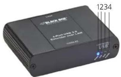
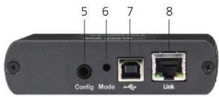
Figure 2-1. Front and back panels of the Local Extender.
Table 2-1. Local Extender components.
| Item Component Description | ||
| 1 Power LED (Blue) | ON when power is supplied.OFF when no power is supplied by the host computer. | |
| 2 Link LED (Green) | ON when valid link is established between the local and remote extenders.Blinking when the IC408A-R2 is in a suspended state.OFF when there is no link between local and remote extenders. | |
| 3 Host LED (Green) | ON when the IC408A-R2 system is properly enumerated on the host computer.Blinking when IC408A-R2 LAN is in a suspended state. | |
| 4 Activity LED (Amber) | ON when data is transmitted between the local and remote extender.Blinks intermittently with or without a USB device connected.OFF when the local and remote extender are in suspend mode. | |
| 5 | Config button | Reserved for manufacturer use. |
| 6 Mode button Reserved for manufacturer use. | ||
| 7 USB Type B connector | Used to connect the local extender to the host computer. Local extender port accepts USB 2.0 Type B connectors. | |
| 8 Link Port (RJ-45) | Local extender accepts an RJ-45 connector for CAT5e (or better) cable to connect the local extender to the remote extender. | |
2.4.2 Remote Extender
The Remote Extender provides four downstream Type A ports for USB 2.0 devices. It enables you to connect up to two USB 2.0 devices directly. The Remote Extender is powered by an external AC adapter and can supply up to 1 A to each USB port.
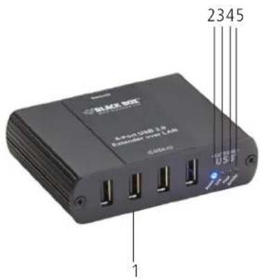
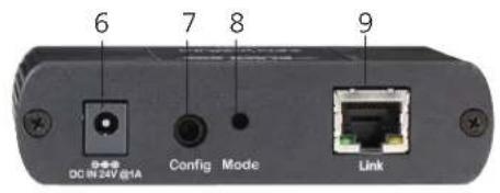
Figure 2-2. Front and back panels of the Remote Extender.
Table 2-2. Remote Extender components.
| Item Component Description | ||
| 1 USB device ports Accepts USB device(s) using Type A connectors. | ||
| 2 Power LED (Blue) | ON when the unit is powered.OFF when the unit is not powered. | |
| 3 Link LED (Green) | ON when local and remote extenders are linked.OFF when there is no link between the local and remote extenders.Fast blinking when the unit unit is attempting to establish a link. | |
| 4 Host LED (Green) | ON when the IC408A-R2 system is properly enumerated on the host computer.Blinking when the IC408A-R2 is in a suspended state. | |
| 5 Activity (Amber) | ON when data is transmitted between the local and remote extenders.Blinking intermittently with or without a USB device connected.OFF when the local and remote extender units are in suspend mode. | |
| 6 | Power Port | Connects to the AC power supply. Required at the remote extender for proper operation. |
| 7 | Config button | Reserved for manufacturer use. |
| 8 Mode button Reserved for manufacturer use. | ||
| 9 Link Port (RJ-45) | Remote extender accepts an RJ-45 connector for CAT5e (or better) cabling to connect the local extender to the remote extender. | |
3. Installation
3.1 Installing the IC408A-R2 on a Local Area Network
3.1.1 Requirements
To complete the installation, you will also need the following items that are not included with the product.
- USB compatible computer (host computer) with a USB-compliant operating system.
- USB compatible device(s).
• (2) CAT5e patch cables - Preconfigured local area network.
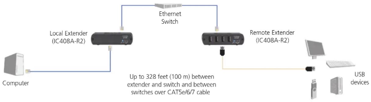
flowchart
graph LR
    A["Computer"] --> B["Local Extender (IC408A-R2)"]
    B --> C["Ethernet Switch"]
    C --> D["Remote Extender (IC408A-R2)"]
    D --> E["USB devices"]
    B -->|Up to 328 feet (100 m) between extender and switch and between switches over CAT5e/6/7 cable| F["Computer"]
Figure 3-1. IC408A-R2 installed on a local area network.
3.1.2 Preparing Your Network
Your network must be properly configured for full USB 2.0 throughput and for maximum stability and reliability of your devices. Consult with your network administrator before installation. Using the IC408A-R2 over a network requires:
- Local Extender and Remote Extender to be on the same subnet.
- RJ-45 information outlets to be near the computer and USB devices to be connected to the network switch(es).
- Pre-installed and configured Local Area Network.
NOTE: USB 2.0 is capable of consuming up to 480 Mbps. The minimum requirement for using the IC408A-R2 is a Gigabit (1000BASE-T) network. The performance of the USB network extension will be limited to the slowest link between the Local and the Remote Extender.
NOTE: Some networks may be configured to block devices with unfamiliar MAC addresses. In this case, you will need to provide your network administrator the MAC addresses of the Local and Remote Extender units. The addresses are on the label on the bottom of each unit.
NOTE: Some networks may be configured to block devices that consume a consistently high level of bandwidth. The IC408A-R2 may do this when high bandwidth devices are connected. Consult with your network administrator to resolve this.
NOTE: Units will be paired with each other if they were sold together in the same box. If they are not paired, follow the instructions provided in the section for pairing a Local and Remote Extender.
NOTE: Increasing the number of switches between the Local and Remote Extender may reduce the available bandwidth, preventing some devices from functioning properly.
3.1.3 Preparing Your Site
Before you can install the IC408A-R2, you need to prepare your site:
- Place the computer where desired and set it up.
- Make sure that where you want to locate the USB device(s) is within 330 feet (100 m) of CAT5e cabling of the switch.
- Make sure that where you want to locate the computer is within 330 feet (100 m) of CAT5e cabling of the switch.
NOTE: The cable distance between switches must be no greater than 330 feet (100 m) if CAT5e is used as the connection media.
3.1.4 Installing the Local Extender
- Place the Local Extender near the computer.
- Connect the supplied USB cable between the Local Extender host port and a USB port on the host computer.
- Connect a CAT5e patch cable (not provided) into the information outlet near the host computer.
- Connect the patch cable into the Link port of the Local Extender.
3.1.5 Installing the Remote Extender
- Connect a CAT5e patch cable (not provided) into the information outlet near the USB devices.
- Connect the patch cable into the Link port of the Remote Extender.
- Place the Remote Extender near the USB device(s).
- Assemble the power adapter and country-specific power cord together and connect them into a suitable AC outlet.
- Connect the power adapter to the Remote Extender.
3.2 Installing the IC408A-R2 System as Direct Connect
3.2.1 Requirements
To complete the installation, you will need the following items that are not included with the product:
- USB compatible computer (host computer) with a USB compliant operating system.
- USB compatible device(s).
- CAT5e Unshielded Twisted Pair (UTP) cable with two RJ-45 connectors (if using surface cabling), OR, CAT5e cabling with two information outlets and two CAT5e patch cords with RJ-45 connectors (if using premise cabling).
3.2.2 Preparing Your Site
Before you can install the IC408A-R2, you need to prepare your site:
- Place the computer where desired and set it up.
- Ensure that where you want to locate the USB device(s) is within 330 feet (100 m) cable-length of the computer. If not, adjust the location of the devices and/or computer accordingly.
- If you are using surface cabling, install the CAT5e cabling as desired and terminate it with the appropriate RJ-45 ends.
If you are using premise cabling, make sure CAT5e cabling is installed between the two locations, and, if necessary, patched together. CAT5e information outlets should be located near the computer and the USB device(s), and the total length, including patch cords, must be less than 330 feet (100 m).
NOTE: Cable installation is important, particularly if high-throughput applications are used. When installing, make sure the cable is installed away from or isolated from potential sources of interference such as electrical wiring, fluorescent lighting, etc.
NOTE: When terminating cables, make sure the matching RJ-45 connector is used for the cable type. For example, if CAT6 cable is used, then CAT6 compatible RJ-45 connectors must be used. If not, the benefits of higher grade cabling may not be achieved.
3.2.3 Installing the Local Extender
- Place the Local Extender near the computer.
- Connect the supplied USB cable between the Local Extender host port and a USB port on the host computer.
3.2.4 Connecting the Local Extender to the Remote Extender
With Surface Cabling
- Connect the CAT5e cable into the Link port of the Local Extender.
- Connect the CAT5e cable into the Link port of the Remote Extender.
With Premise Cabling
- Connect a CAT5e patch cable (not provided) into the information outlet near the host computer.
- Connect the patch cable into the Link port of the Local Extender.
- Connect a CAT5e patch cable (not provided) into the information outlet near the USB devices.
- Connect the patch cable into the Link port of the Remote Extender.
3.2.5 Installing the Remote Extender
- Place the Remote Extender near the USB device(s).
- Assemble the power adapter and U.S. power cord together and connect them into a suitable AC outlet.
- Connect the power adapter to the Remote Extender.
3.3 Checking the Installation
- On the Local and Remote Extender, check that the Power, Link, and Host LEDs are on.
- For direct connect, if the Host or Link LEDs are permanently off, then the cabling between the Local and Remote Extender may not be installed properly or is defective.
- For network connect, if the Link LED is blinking, then the network connection between the Local and Remote Extender is not complete and there may be faulty cabling or network components, misconfigured network components, or the Local and Remote Extender may need to be re-paired together (see Section 3.5).
- For Windows® users, open Device Manager to confirm that the IC408A-R2 has installed correctly. To expand the entry for Universal Serial Bus controllers, click the "+" sign. If the IC408A-R2 has been installed correctly, you should find it listed as a "Generic USB Hub."
NOTE: To open Device Manager in Windows 7 or 8: Open the Start menu, right-click on "Computer," then select: "Manage >> Device Manager."
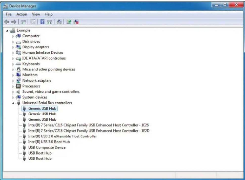
Figure 3-3. Device Manager screen.
- For Mac OS X users, open the System Profiler to confirm that the IC408A-R2 has installed correctly. In the left-hand column under Hardware, select "USB" and inspect the right-hand panel. If the IC408A-R2 has been installed correctly, you should find it listed as a "Hub""under the USB High-Speed Bus/USB Bus.
NOTE: To open System Profiler in OS X: Open the Finder, select "Applications," then open the "Utilities" folder and double-click on the "System Profiler" icon.
- If the IC408A-R2 is not detected correctly or fails to detect, consult Section 4, Troubleshooting.
3.4 Connecting a USB Device
- Install any software required to operate the USB device(s). Refer to the documentation for the USB device(s).
- Connect the USB device to the device port on the Remote Extender.
- Check that the device is detected and installed properly in the operating system.
3.5 Pairing the Local and Remote Extender
The Local Extender and a Remote Extender will be paired with each other out of the box, so no pairing action should be required. However, if individual extenders have been installed, or you simply wish to change the Local and Remote Extender pairings across a network, then follow these steps (they apply to both direct connect and network configurations for the IC408A-R2):
- Make sure the Local and Remote Extenders are either directly connected to each other, or are connected to the same subnet on your network.
- Press and hold the "Pair" button on the back of the Local Extender. Release the button within 10 seconds. The Link LED will start flashing.
- Within 10 minutes of activating the pair mode on the Local Extender, press and hold the "Pair" button on the back of the Remote Extender. Release the button within 10 seconds. The Link LED will start flashing.
- The Link LED on both units may start flashing more slowly before finally turning on. Once the Link LEDs are solid, the link is established between both extenders.
NOTE: If more than 10 minutes passes before the units are paired, then the extenders will switch back to regular mode and re-establish the previous links they had, if any.
NOTE: To cancel pair mode, press and hold the "Pair" button a second time. Release it within 10 seconds.
3.6 Unpairing an Extender
If an extender needs to have its pairing removed, press and hold the "Pair" button for longer than 10 seconds. Once you do this, the unit will not be paired to any other extender.
3.7 Compatibility
The IC408A-R2 complies with USB 1.1 and USB 2.0 specifications governing the design of USB devices. However, there is no guarantee that all USB devices or hosts will be compatible with the IC408A-R2, as there are a number of different characteristics that may impact the operation of USB devices over extended distances.
4. USB Extender Mounting Options
The bottoms of the IC408A-R2 enclosures feature four convenient pre-drilled holes for optional mounting. Based on your requirements, choose from two available mounting options:
- USB Extender Mounting Kit (part number IC400MK)
- USB Extender Direct Surface Mounting (Using your own hardware, stencil provided on the next page)
OPTION 1: USB Extender Mounting Kit - each kit includes:
• (2) mounting brackets
• (4) (M3.0) locking washers
• (4) (M3.0 x 5-mm) Phillips pan head screws
Mounting Bracket Installation
NOTE: One kit is required to mount a Local Extender or Remote Extender; two kits per system.
Using a Phillips screwdriver, in the order as illustrated below, fasten and secure the provided screws, locking washers and brackets into place.
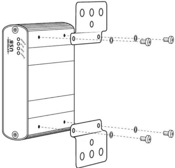
Figure 4-1. Installing the mounting brackets.
Once the bracket mounting is secured onto the extender, it is ready for mounting onto a surface.
NOTE: You will need to provide your own screws to secure the extender using the available slots on each bracket.
OPTION 2: USB Extender Direct Surface Mounting (using your own hardware)
The bottoms of the IC408A-R2 enclosures features four pre-drilled holes for optional surface mounting.
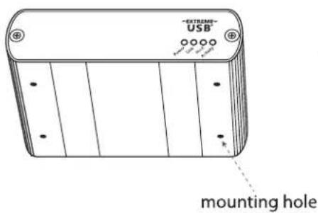
Distance between the enclosure mounting holes: 42.0 mm x 77.0 mm
Figure 4-2. Mounting hole on the IC408A-R2 enclosure.
- Mark the center point of each of the four holes on your mounting surface either by directly measuring or using a print out of the stencil below.
- Hardware recommendation: M3.0 locking washers and M3.0 screws (4 of each per extender) noting screw length will depend upon thickness of mounting surface.
- Drill through each of the four hole markings on the mounting surface using a 4.7625mm (3/16") drill bit.
- Align the bottom enclosure holes to the newly drilled out holes on the mounting surface.
- Place a locking washer on each of the four screws and using a screwdriver, fasten the extender into place
NOTE: To ensure the stencil below prints to scale be sure to set the page scaling setting to "none".
Direct Surface Mounting Measurement Stencil
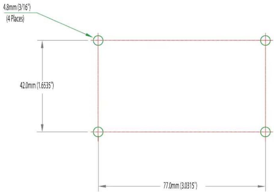
Figure 4-3. Mounting stencil.
5. Troubleshooting
5.1 Troubleshooting Tips
The following troubleshooting tips are arranged in the order in which they should be executed (in most situations). If you are unable to resolve the problem after following these instructions, contact Black Box Technical Support at 877-877-2269 or info@blackbox.com.
Problem: All LEDs on the Local Extender are off.
Cause: The Local Extender is not receiving power from the USB port.
Solution(s):
- Make sure that the USB connection between the Local Extender and host computer is properly installed.
- Move the USB connector to another USB port on the host computer.
Problem: All LEDs on the Remote Extender are off.
Cause: The Remote Extender is not receiving power from the AC adapter.
Solution(s):
- Make sure that the AC power adapter is properly connected to the Remote Extender.
- Check that the AC adapter is connected to a live source of electrical power. Check that the remote power LED is illuminated.
Problem: Link LEDs on Local and the Remote Extenders are off.
Cause(s): There is no connection between the Local and Remote Extenders.
Solution(s):
- Make sure that CAT5e cable is connected between the Local and Remote Extenders. Use CAT5e or better cable, UTP with a straight-through connector and no crossovers, and 8-conductor RJ-45 connectors at both ends.
- Connect a short CAT5e patch cord between the Local and Remote Extenders to determine if the original CAT5e cable is defective.
Problem: Link LEDs are blinking.
Cause(s):
- There is no connection between the Local and Remote Extenders.
- Units may not be paired to each other.
- Network switches exist on different subnets.
- Network switch(es) are blocking traffic from the extenders.
Solution(s):
- Make sure both the Local and Remote Extenders are connected together directly or are connected to active network switches.
- Re-pair the units together.
-
Make sure the network switches can communicate with each other and are on the same subnet.
-
Make sure the network switches are not blocking traffic from the extenders, either based on MAC address or because of traffic patterns.
- Consult with your network administrator.
Problem: Link LEDs on the Local and Remote Extenders are blinking slowly.
Cause: The extenders are paired with each other, but have not yet established a link.
Solution(s):
- Wait for a few minutes for the LEDs to go solid.
- If LEDs do not go solid, contact your network administrator to determine if any traffic is being blocked between the extenders.
Problem: Link LED on the Local Extender is on, Host LED on the Local Extender is off.
Cause:
- The host computer is not powered on.
- The Local Extender is not connected to the computer.
- The host computer is not recognizing the Local Extender.
- The computer does not support USB hubs.
- The IC408A-R2 is malfunctioning.
Solution(s):
- Disconnect all USB devices from the Remote Extender.
- Disconnect the Local Extender from the computer.
- Disconnect the Remote Extender from the AC power adapter.
- Reconnect the Local Extender to the computer.
-
Reconnect the Remote Extender to the computer.
-
In the Universal Serial Bus (USB) controllers section of Device Manager, check that the IC408A-R2 is recognized as "Generic USB Hub."
Problem: My USB device does not work properly.
Cause: Insufficient bandwidth is available on the network to support the device.
Solution: Connect the Local and Remote Extenders directly to each other and try the USB device again.
Problem: My USB device does not work at all.
Cause(s):
- Insufficient bandwidth is available on the network to support the device.
- The Local Extender is paired to the wrong Remote Extender.
Solution(s):
- Connect the Local and Remote Extenders directly to each other and try the USB device again.
- Follow the instructions in Section 3.5 and pair the Local to the Remote Extender that is connected to the device you wish to use.
4.2 Contacting Black Box
If you determine that your 4-Port USB 2.0 Extender over LAN is malfunctioning, do not attempt to alter or repair the unit. It contains no user-serviceable parts. Contact Black Box Technical Support at 877-877-2269 or info@blackbox.com.
Before you do, make a record of the history of the problem. We will be able to provide more efficient and accurate assistance if you have a complete description, including:
- the nature and duration of the problem.
- when the problem occurs.
- the components involved in the problem.
- any particular application that, when used, appears to create the problem or make it worse.
4.3 Shipping and Packaging
If you need to transport or ship your 4-Port USB 2.0 Extender over LAN:
- Package it carefully. We recommend that you use the original container.
- If you are returning the unit, make sure you include everything you received with it. Before you ship for return or repair, contact Black Box to get a Return Authorization (RA) number.
6. Technical Glossary
Category 5 (CAT5) Network Cabling — Category 5 cable is commonly also referred to as CAT5. This cabling is available in either solid or stranded twisted pair copper wire variants and as UTP (Unshielded Twisted Pair) or STP (Shielded Twisted Pair). UTP cables are not surrounded by any shielding, making them more susceptible to electromagnetic interference (EMI). STP cables include shielding over each individual pair of copper wires that provides better protection against EMI. Category 5 has been superseded by CAT5e cabling, which includes improved data integrity to support high-speed communications.
USB Cables — USB cables have two distinct connectors. The Type A connector is used to connect the cable from a USB device to the Type A port on a computer or hub. The Type B connector is used to attach the USB cable to a USB device.
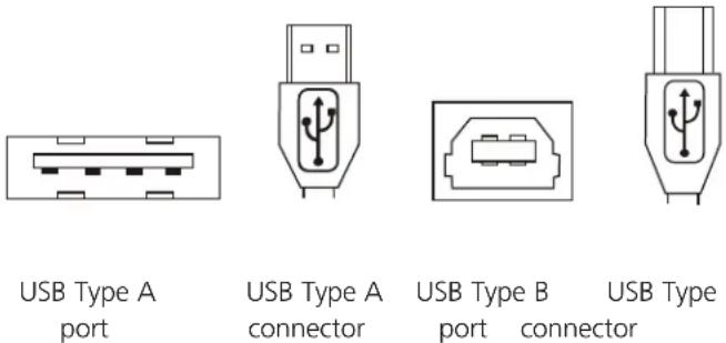
Figure 5-1. USB cables.
RJ-45 — The Registered Jack (RJ) physical interface is what connects the network cabling (CAT5) to the local extender and remote extender. You may use either the T568A scheme (Table 5-1) or the T568B scheme (Table 5-2) for cable termination because the extender uses all four pairs of the cable. RJ-45 connectors are sometimes also referred to as 8P8C connectors.
RJ-45 Pin Positioning —
Table 5-1. T568A wiring.
| Pin Pair Wire Cable Color |
| 1 3 1 White/Green |
| 2 3 2 Green |
| 3 2 1 White/Orange |
| 4 1 2 Blue |
| 5 1 1 White/Blue |
| 6 2 2 Orange |
| 7 4 1 White/Brown |
| 8 4 2 Brown |
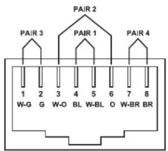
Figure 5-2. T568A connector pinout.
Table 5-2. T568B wiring.
| Pin Pair Wire Cable Color | |
| 1 2 1 White/Orange | |
| 2 2 2 Orange | |
| 3 3 1 White/Green | |
| 4 1 2 Blue | |
| 5 1 1 White/Blue | |
| 6 3 2 Green | |
| 7 4 1 White/Brown | |
| 8 4 2 Brown | |
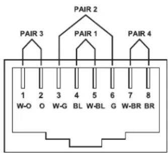
Figure 5-3. T568B connector pinout.
Black Box Tech Support: FREE! Live. 24/7.
Tech support the way it should be.

natural_image
Close-up portrait of a smiling man with short hair, wearing a headset, against a blue gradient background (no text or symbols visible)Great tech support is just 60 seconds away at 877-877-2269 or blackbox.com.

BLACK BOX®
About Black Box
Black Box provides an extensive range of networking and infrastructure products. You'll find everything from cabinets and racks and power and surge protection products to media converters and Ethernet switches all supported by free, live 24/7 Tech support available in 60 seconds or less.
© Copyright 2016. Black Box Corporation. All rights reserved. Black Box ^® and the Double Diamond logo are registered trademarks of BB Technologies, Inc. Any third-party trademarks appearing in this manual are acknowledged to be the property of their respective owners.
ic408A-r2_user_rev2
- 4-Port USB 2.0 Extender over LAN
- Easily extend USB 2.0 signals over an IP network or directly over a CATx link.
- Trademarks Used in this Manual
- Federal Communications Commission and Industry Canada Radio Frequency Interference Statements
- Overview
- Introduction
- Features
- What's Included
- Hardware Description
- Local Extender
- Remote Extender
- Installation
- Installing the IC408A-R2 on a Local Area Network
- Requirements
- Preparing Your Network
- Preparing Your Site
- Installing the Local Extender
- Installing the Remote Extender
- Installing the IC408A-R2 System as Direct Connect
- Requirements
- Preparing Your Site
- Installing the Local Extender
- Connecting the Local Extender to the Remote Extender
- With Surface Cabling
- With Premise Cabling
- Installing the Remote Extender
- Checking the Installation
- Connecting a USB Device
- Pairing the Local and Remote Extender
- Unpairing an Extender
- Compatibility
- USB Extender Mounting Options
- Mounting Bracket Installation
- Troubleshooting
- Troubleshooting Tips
- Solution(s):
- Cause(s):
- Cause:
- Contacting Black Box
- Shipping and Packaging
- Technical Glossary
- RJ-45 Pin Positioning —
- Black Box Tech Support: FREE! Live. 24/7.
- BLACK BOX®
- About Black Box
Brand : Black Box
Model : IC408A-R2
Category : Wi-Fi repeater