
LWE121A - Wi-Fi repeater Black Box - Free user manual and instructions
Find the device manual for free LWE121A Black Box in PDF.


| Product Type | Wi-Fi Repeater |
| Brand | Black Box |
| Model | LWE121A |
| Wireless Standards | IEEE 802.11a/b/g/n/ac |
| Frequency Bands | 2.4 GHz and 5 GHz |
| Maximum Data Rate | 1200 Mbps (300 Mbps on 2.4 GHz + 867 Mbps on 5 GHz) |
| Antenna Type | Internal antennas |
| Interface | 1 x RJ45 Gigabit Ethernet port |
| Dimensions (W x D x H) | 80 x 50 x 30 mm |
| Weight | 100 g |
| Power Supply | 5V DC, 1A via micro USB |
| Power Consumption | < 5W |
| Main Functions | Extends Wi-Fi coverage, WPS button, AP mode, Repeater mode |
| Security | WPA/WPA2-PSK encryption |
| LED Indicators | Power, Wi-Fi, Ethernet, Signal strength |
| Operating Temperature | 0°C to 40°C |
| Storage Temperature | -20°C to 60°C |
| Humidity | 10% to 90% non-condensing |
| Maintenance | Clean with a soft, dry cloth. Do not use liquids or solvents. |
| Safety | Keep away from water and moisture. Do not disassemble. |
| Spare Parts / Repairability | No user-serviceable parts. Contact support for repairs. |
| Package Contents | Wi-Fi Repeater, micro USB cable, quick installation guide |
Frequently Asked Questions - LWE121A Black Box
User questions about LWE121A Black Box
0 question about this device. Answer the ones you know or ask your own.
Ask a new question about this device
Download the instructions for your Wi-Fi repeater in PDF format for free! Find your manual LWE121A - Black Box and take your electronic device back in hand. On this page are published all the documents necessary for the use of your device. LWE121A by Black Box.
USER MANUAL LWE121A Black Box
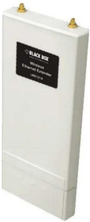
Wireless Ethernet Extender
User Manual
- Operates at 2.4-GHz to provide superior Wi-Fi connectivity at a low cost.
- Use for SMB or hotspot networks.
- Provides centralized management and monitoring of all the VAC-managed APs on the network.
Trademarks Used in this Manual
Black Box and the Double Diamond logo are registered trademarks of BB Technologies, Inc.
Any other trademarks mentioned in this manual are acknowledged to be the property of the trademark owners.
Disclaimer:
Black Box Network Services shall not be liable for damages of any kind, including, but not limited to, punitive, consequential or cost of cover damages, resulting from any errors in the product information or specifications set forth in this document and Black Box Network Services may revise this document at any time without notice.
We're here to help! If you have any questions about your application or our products, contact Black Box Tech Support at 724-746-5500 or go to blackbox.com and click on "Talk to Black Box."
You'll be live with one of our technical experts in less than 60 seconds.
Federal Communications Commission and Industry Canada Radio Frequency Interference Statements
This equipment generates, uses, and can radiate radio-frequency energy, and if not installed and used properly, that is, in strict accordance with the manufacturer's instructions, may cause interference to radio communication. It has been tested and found to comply with the limits for a Class A computing device in accordance with the specifications in Subpart B of Part 15 of FCC rules, which are designed to provide reasonable protection against such interference when the equipment is operated in a commercial environment. Operation of this equipment in a residential area is likely to cause interference, in which case the user at his own expense will be required to take whatever measures may be necessary to correct the interference.
Changes or modifications not expressly approved by the party responsible for compliance could void the user's authority to operate the equipment.
This digital apparatus does not exceed the Class A limits for radio noise emission from digital apparatus set out in the Radio Interference Regulation of Industry Canada.
FCC Radiation Exposure Statement
This equipment complies with FCC radiation exposure limits set forth for an uncontrolled environment. To avoid the possibility of exceeding radio frequency exposure limits, you shall beep a distance of at least 100 cm between you and the antenna of the installed equipment. This transmitter must not be co-located or operating in conjunction with any other antenna or transmitter.
The availability of some specific channels and/or operational frequency bands are country dependent and are firmware programmed at the factory to match the intended destination. The firmware setting is not accessible by the end user.
- Specifications....8
- Overview 9
2.1 Description 9
2.2 Features....9
2.3 What's Included 9
2.4 Hardware Description....10
2.5 Typical Management Scenario....12
- Installation 13
3.1 Preparing for Installation.... 13
3.2 Safety Precautions 13
3.3 Installation Precautions....13
3.4 System Installation....13
3.4.1 Connect Up....13
3.4.2 Using the Grounding Wire 14
3.4.3 Install the External Antennas....15
3.4.4 Mount the AP on a Pole....17
3.4.5 Power Up 18
3.4.6 Connect to the Extender 18
- Quick Setup Tutorial 21
4.1 Access the Web Configurator....21
4.2 Configure the AC+Thin AP Mode 22
4.3 Firmware Upgrade for Ethernet Extender in AC mode....24
4.4 Install the Managed Thin AP 24
4.5 Manage the Extender-Managed APs....25
4.6 Firmware Upgrade for Managed Thin APs 26
4.7 Monitor the Ethernet Extender-Managed APs....28
4.8 Configure the Fat AP Mode....28
4.8.1 AP Mode 29
4.8.2 Wireless Client Mode 31
4.8.3 Bridge Mode 33
4.8.4 AP Repeater Mode 34
- Navigating the Web Configurator ....36
5.1 Virtual AC+Thin AP Mode 36
5.1.1 Status 36
View Basic Information....36
View Managed APs....36
View Wireless Users 37
View DHCP Client Table 37
5.1.2 Wireless Settings 37
Wireless Networks (VAP Profiles Settings) 37
Network Basic Setting 41
Wireless Protocols....41
Access Control....43
Traffic Shaping....43
Radius Settings 44
Captive Portal 46
Firewall Settings....47
5.1.3 Management....50
AP Management 50
System Settings 53
Time Settings....55
Firmware Upgrade....55
Backup/Retrieve Settings....56
Restore Factory Default Settings....56
Reboot....57
Password Settings 58
Syslog Settings 58
System Log 60
5.1.4 Tools 60
Ping 61
Trace Route 61
5.2 Thin AP Mode 62
5.2.1 Information....62
5.2.2 Basic Settings....62
5.3 Fat AP Mode 63
5.3.1 Status 63
View Basic Information....63
View Association List....64
View Network Flow Statistics 64
View ARP Table 65
View Bridge Table....66
View Active DHCP Client Table....66
View Network Activities 67
5.3.2 System....67
Basic System Settings 67
TCP/IP Settings 68
Time Settings....69
RADIUS Settings....70
Firewall Settings....71
UDP Passthrough....74
DMZ 75
5.3.3 Wireless....75
VAP Profile Settings....78
VLAN....80
Advanced Settings....81
Access Control....83
Traffic Shaping....84
Captive Portal 84
WDS Settings 85
5.3.4 Management....86
Password 86
Upgrade Firmware....87
Backup/Retrieve Settings....87
Restore Factory Default Settings....88
Reboot....89
Remote Management....89
SNMP Management....90
Certificate Settings 91
5.3.5 Tools....91
System Log 91
Ping Watchdog....92
Site Survey....93
Data Rate Test 93
Antenna Alignment....94
Speed Test....94
Appendix. ASCII 95
- Specifications
| Approvals RoHS | |
| Configuration on File | Backup and restore, Reset to factory default, Reboot device injector via PoE |
| Environmental | Operating temperature: -4 to +158°F (-20 to +70°C);Storage temperature: -40 to +158°F (-40 to +70°C);Humidity: 10-95% noncondensing |
| Management | Operating Modes: Virtual Access Controller (VAC), Thin AP, FAT AP (AP, Wireless Client,Bridge, AP Repeater);Access Method: Web User Interface (HTTP/S), Telnet, SSH, FTP, SNMP V1, V2c, V3;Restore Factory Default: Web, Push button |
| Interfaces (1) 10/100BASE-T RJ-45 | |
| Connectors (1) RJ-45; | (1) Grounding screw;(2) connectors for detachable external 2.4 GHz 5 dBi Omni-directional Antennas |
| Indicators (4) LEDs: Power, WLAN, LAN, Signal | |
| Environmental | Operating temperature: -4 to +158°F (-20 to +70°C);Storage temperature: -40 to +158°F (-40 to +70°C);Humidity: 10-95% noncondensing |
| Power 24 V | |
| Dimensions | Each unit: 10.06"H x 4.37"W x 1.88"D (25.56 x 11.10 x 4.77 cm) |
| Weight Each unit: 1.1 lb (0.5 kg) | |
| LWE121A Wireless Specifications | |
| Antennas (2) external 2.4 GHz 5 dBi Omni-directional Antennas | |
| Data Rates | 802.11b: 1, 2, 5.5, 11; 802.11g: 6, 9, 12, 18, 24, 36, 48, 54; 802.11n: MCS0 to MCS15(6.5 Mbps to 300 Mbps per radio) |
| Radio Chains | 2x2 MIMO with two spatial streams |
| Standards | IEEE 802.11b/g/n, 2.4 GHz |
| Frequency | 802.11 b/g/n: 2.4 – 2.484 GHz |
| Operating Channels | 2.4 GHz – FCC 1-11; ETSI 1-13 |
| RF Output Power | 2.4 GHz: 30dBm (2 TX) (The maximum power setting will vary by channel and accordingto individual country regulations.) |
| Receive Sensitivity | IEEE 802.11b: 85 dBm @ 11 Mbps; IEEE 802.11g: 89 dBm @ 6 Mbps; IEEE 802.11n: 86 dBm@ HT20, 83 dBm @ HT40 |
| Security | Open, Share key (64/128/152-bits WEP;, Legacy 802.1X; WPA WAP2, WPA-PSK(TKIP),WPA2-PSK(AES), WPA-PSK + WPA2-PSK |
2. Overview
2.1 Introduction
The Wireless Ethernet Extender is a multimode 2x2 outdoor access point embedded with a software-based virtual access controller (VAC). The LWE120A operates at 2.4-GHz band. Ideally suited for SMB or hotspot networks, this breakthrough innovation provides superior Wi-Fi network solutions at significantly lower cost.
In addition, the easy-to-install Wireless Ethernet Extender is also a high-performance last-mile broadband solution that provides reliable wireless network coverage for outdoor broadband application.
While operating as access point, the Wireless Ethernet Extender also provides centralized management and monitoring of all the VAC-managed APs on the network. In addition, the easy-to-install Wireless Ethernet Extender is also a high-performance last-mile broadband solution that provides reliable wireless network coverage for outdoor broadband application.
2.2 Features
- Centralized configuration control for your network.
- Compliant with IEEE 802.11n standard.
• Support passive PoE supplied with 24V. - High reliable watertight housing endures almost any harsh environments.
- Three management modes including AC, AC+Thin AP, Thin AP and Fat AP.
- Four wireless operation modes in FAT AP mode including AP, Wireless Client, WDS, and AP Repeater.
- Up to 8 BSSIDs available for service deployment.
- Support encryption: 64/128/152-bit WEP and 802.1X, WPA, WPA2, WPA & WPA2, WPA-PSK, WPA2-PSK, and WPA-PSK & WPA2-PSK.
- User-friendly Web and SNMP-based management interface.
2.3 What's Included
Your package should contain the following items. If anything is missing or damaged, contact Black Box Technical Support at 724-746-5500 or info@blackbox.com.
The LWE121A and LWE120AE packages contain the following items:
• (1) IEEE 802.11n Wireless Ethernet Extender
• (2) detachable 5-dBi antennas
• (2) pole-mounting rings
• (1) 24-VDC power cord and PoE injector
• (1) ferrite suppression core
• (1) grounding wire
• This printed quick installation guide
The LWE121A-KIT and LWE120AE-KIT packages contain two each of the items listed above for LWE120A and LWE120AE.
To download this user manual from the Web site:
- Go to www.blackbox.com
- Enter the part number (LWE121A) in the search box:
- Click on the "Resources" tab on the product page, and select the document you wish to download.
NOTE: Users MUST use the power cord and PoE injector shipped in the box with the Wireless Ethernet Extender. Using other options will damage the unit.
2.4 Hardware Description
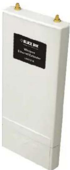
Figure 2-1. Front view.

Figure 2-2. Back view.

Figure 2-3. Inside the bottom cover.
| Table 2-1. LED indicators. | |||
| LED Color | Status Description | ||
| PWR Green | ON The device is powered on. | ||
| LAN | Green | ON | The device has an Ethernet connection. |
| OFF The device has no Ethernet connection. | |||
| Blinking Transmitting/receiving Ethernet packets. | |||
| WLAN Green ON The WLAN is active. | |||
| Signal Green 3 LED ON | The signal strength is excellent. | ||
| 2 LED ON The signal strength is good. | |||
| 1 LED ON The signal strength is weak. | |||
2.5 Typical Management Scenario
This section describes the typical management of the Wireless Ethernet Extender. By default, it is set to thin AP mode (managed AP) which allows it to be managed by the Wireless Ethernet Extender in AC mode.
When a thin AP mode joins a wired network, it will start to look for a Wireless Ethernet Extender in AC mode. If the thin AP finds the AP controller on the network, it will send the registration request to the AP controller. Once the registration is successfully made, the AP that acts as the AP controller will add the thin AP to its management list and provides it configuration information.
3. Installation
3.1 Preparing for Installation
CAUTION: Professional Installation Required. Seek assistance from a professional installer who is well trained in RF installation and knowledgeable in the local regulations.
3.2 Safety Precautions
To keep you safe and install the hardware properly, read and follow these safety precautions.
- If you are installing the Wireless Ethernet Extender for the first time, for your safety as well as others', please assistance from a professional installer who has received safety training on the hazards involved.
- Keep safety as well as performance in mind when selecting your installation site, especially where there are electric power and phone lines.
-
When installing the Wireless Ethernet Extender, note the following things:
-
Do not use a metal ladder;
- Do not work on a wet or windy day;
- Wear shoes with rubber soles and heels, rubber gloves, and a long-sleeved shirt or jacket.
- When the system is operational, avoid standing directly in front of it. Strong RF fields are present when the transmitter is on.
3.3 Installation Precautions
To keep the Wireless Ethernet Extender well while you are installing it, read and follow these installation precautions.
- Users MUST use a proper and well-installed grounding and surge arrestor with the Wireless Ethernet Extender; otherwise, random lightning could easily cause fatal damage to the unit.
WARNING: EMD (Lightning) DAMAGE IS NOT COVERED UNDER WARRANTY.
- Users MUST use the power cord and PoE injector shipped in the box with the Wireless Ethernet Extender. Using other options will damage the unit.
- Users MUST power off the Wireless Ethernet Extender first before connecting the external antenna to it. Do not switch from the built-in antenna to the external antenna from Web management without physically installing the external antenna onto the unit. Otherwise, the Wireless Ethernet Extender might be damaged.
3.4 System Installation
3.4.1 Connect up
Connect up
- The bottom of the Wireless Ethernet Extender is a movable cover. Grab the cover and pull it back harder to take it out as the figure shown below.

natural_image
White electronic device with a black top and red arrow indicating a process, shown in two views (no text or symbols)Figure 3-1. Removing the bottom cover from the extender.
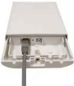
- Plug a standard Ethernet cable into the RJ-45 port.
natural_image
White electronic device with exposed internal components and a cable inserted (no visible text or symbols)Figure 3-2. Plugging a standard Ethernet cable into the RJ-45 port.
- Slide the cover back and press down the lock button to seal the bottom of the Wireless Ethernet Extender.

natural_image
White electronic device with a cable and connector, no visible text or symbolsFigure 3-3. Replacing the bottom cover.
3.4.2 Using the Grounding Wire
The extender has a grounding wire. Be sure to connect the extender, cables, and PoE injector to earth ground properly during normal use to protect against surges or ESD.
- Remove the screw on the grounding point at the bottom of the Wireless Ethernet Extender.

Figure 3-4. Grounding point on the extender.
- Put the grounding wire on the grounding point at the bottom of the Wireless Ethernet Extender. Then screw the grounding wire to tighten up.

natural_image
Interior view of a beige electronic device housing with visible internal components and a green cable (no text or symbols)Figure 3-5. Tighten the grounding wire.
- Connect the grounding wire to earth ground.
3.4.3 Install the External Antenna
The Wireless Ethernet Extender provides two reverse SMA antenna connectors for connecting the external antennas.

Figure 3-6. External antenna connectors.
- Connect your external antennas to the SMA-type connectors on top of the Wireless Ethernet Extender. For longer distance, we recommend using higher-gain antennas to best suit the application.

natural_image
Two white antennas mounted on a light pink rectangular device (no visible text or symbols)Figure 3-7. External antennas connected to the extender.
WARNING: Users MUST power off the extender first before connecting the external antennas to it. Do not power on the device without physically attaching the antenna; otherwise, your extender might be damaged.
- Bend the antenna to 90 degrees or 45 degrees.

Figure 3-8. Bend antenna.
- You may turn one antenna 45 degrees to the left and the other 45 degrees to the right. The tilted antennas couple together much less than if they are both pointed in the same direction.
NOTE: Align the polarization of the antennas properly. Maximum signal strength between bridges occurs when both antennas are using identical polarization.
- Tighten the connector joint clockwise to fix the antennas.

natural_image
Close-up of hands performing a procedure on a white cylindrical object, no visible text or symbolsFigure 3-9. Tighten the connector clockwise.
-
To adjust antennas, loosen the connector joint counterclockwise first, then adjust the antenna to the desired position. DO NOT bend or turn the antennas without loosening the connector joint; otherwise, you might damage the antennas.
-
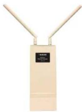
Antenna installation is complete.
natural_image
Exterior view of a beige wireless device with two antennas and a label (no visible text or symbols on the device body)Figure 3-10. Installed antennas.
3.4.4 Mount the AP on a Pole
- Turn the Wireless Ethernet Extender over. Put the pole mounting ring through the middle hole of it.
NOTE: Unlock the pole mounting ring with a screw driver before putting it through the device as the following right picture shows.

natural_image
Close-up of a white electronic device with three ventilation grilles and a green clamp, alongside a red screwdriver (no text or symbols visible)Figure 3-11. Installing the pole mounting ring on the extender.
- Mount the Wireless Ethernet Extender steadily to the pole by locking the pole mounting ring tightly.

natural_image
Exterior view of a white industrial electrical cabinet with a black label (no visible text or symbols on the device body)Figure 3-12. Extender mounted on a pole.
3.4.5 Power Up
- Plug the power cord into the DC port of the PoE injector.

natural_image
Coiled cable and plug device (no visible text or symbols)Figure 3-13. Power cord plugged into the injector's DC port.
-
Connect the power plug to a power socket.
-
Use an Ethernet cable to connect the Wireless Ethernet Extender to the "POE" port of the PoE injector as shown below.
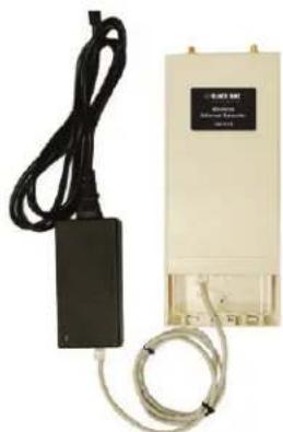
natural_image
Exterior view of a power supply unit with black cable, connected to a black plug and coiled cable (no visible text or symbols)Figure 3-14. Power up the extender.
- Connect the power plug to a power socket. The Wireless Ethernet Extender will be powered up immediately.
3.4.6 Connect to the Extender
To be able to configure and manage the extender, do the following:
- Open the ferrite core by unsnapping the connector latches. The core will open, revealing a concave surface.

Figure 3-15. Open the connector latches.
- Lay the Ethernet cable into the core, usually within 2 to 3 inches of the connector.
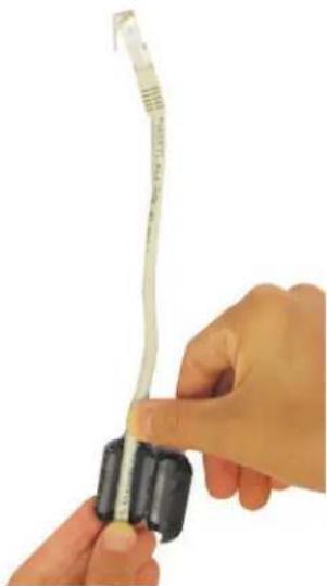
natural_image
Close-up of hands holding a pen-like tool with a ruler, no visible text or symbolsFigure 3-16. Putting cable into the core.
- Loop the cable around and through the core. This helps "lock" the core in place, and may be required in circumstances with severe interference.

natural_image
Close-up of hands using a pen to measure a blood pressure measurement tool (no visible text or symbols)Figure 3-17. Loop cable around core.
- Close the core and snap the halves back together.

natural_image
Close-up of a beige Ethernet cable with a black connector (no text or symbols visible)Figure 3-18. Close core.
- Connect the Ethernet cable with suppression core to the "Data In" port of the PoE injector.
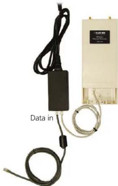
Figure 3-19. Connecting cable to data-in port.
- Connect the other end of the Ethernet cable to a PC or a switch hub. The hardware installation is complete.

natural_image
Network switch device with purple network interface, black cable, and power outlet (no visible text or symbols)Figure 3-20. Completed installation.
4. Quick Setup Tutorial
4.1 Access the Web Configurator
The Wireless Ethernet Extender provides you with user-friendly Web-based management interface to easily manage the access point.
- Configure the computer with a static IP address of 192.168.1.x, as the default IP address of the VAC Access Point is 192.168.1.1. (X cannot be 0, 1, or 255);
- Open a Web browser and enter the IP address (Default: 192.168.1.1) of the Wireless Ethernet Extender into the address field. You will see the login page as below.

Figure 4-1. Login page.
- Enter the username (Default: admin) and password (Default: password) respectively and click "Login" to login the main page of the Wireless Ethernet Extender.

Figure 4-2. Main page.
NOTE: The username and password are case-sensitive, and the password should be no more than 19 characters!
4.2 Configure the AC+Thin AP mode
To operate as AC+Thin AP mode, go to Basic Settings. From the Device Mode drop-down list, select "Virtual AC" mode. To use the extender as a virtual controller and access point concurrently, select "Virtual AC + Thin AP" mode. Then assign an IP address to the Wireless Ethernet Extender and specify subnet mask, gateway, and DNS address, respectively. Press "Apply" and wait for about 50 seconds to take effect.

Figure 4-3. Basic settings screen.
NOTE: AC+ Thin AP mode allows the Wireless Ethernet Extender to operate as access controller and thin AP at the same time.
NOTE: To operate the extender as a standalone Access Point, wireless client, or bridge, select FAT AP from device mode.
For Virtual Controller + Thin AP mode, if you need to configure the wireless settings for the Wireless Ethernet Extender, especially SSID and encryption method, go to Wireless Settings → Wireless Networks and click on "#1 Wireless SSID" for configuration. Click "Save" to save the settings.

Figure 4-4. Wireless Networks screen.

Figure 4-5. Wireless Settings screen.
The wireless setting will also apply to the VAC-managed APs. A dialog message will pop up to remind you changes will also apply to other extender-managed APs. Click "Apply" to apply the configuration immediately.

Figure 4-6. Wireless Settings screen.
To make the change on the Wireless Ethernet Extender itself take effect, you need to reboot the extender. To reboot the Wireless Ethernet Extender, go to Management —> Configuration File and click the "Reboot" button. The reboot process will take about 50 seconds.
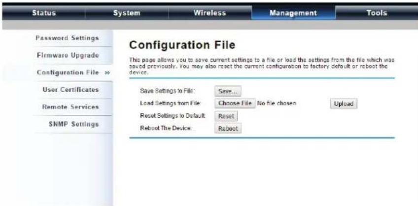
Figure 4-7. Configuration file screen.
4.3 Firmware Upgrade for Ethernet Extender in AC mode
To upgrade the firmware for the Wireless Ethernet Extender in AC mode, go to Management —> Firmware Upload and from Upgrade AC Firmware, browse the firmware file where it is placed. Press "Upload" to start the upgrade process. It will take approximately two minutes to complete the update.

Figure 4-8. Upgrade Firmware screen.
4.4 Install the Managed Thin AP
Install and connect the rest of managed Access Points to your network with the Ethernet cable. Power them up respectively. They will automatically discover the Wireless Ethernet Extender in AC mode and issue registration request.
To check whether the thin APs are successfully registered or not, enter the web page of the Wireless Ethernet Extender master access controller and go to Management —> AP Management. You will see "Registered" in the Status column. You can also see other information, such as MAC address, IP address, FW version, number of clients that associate to each thin AP, and upload/download speed.
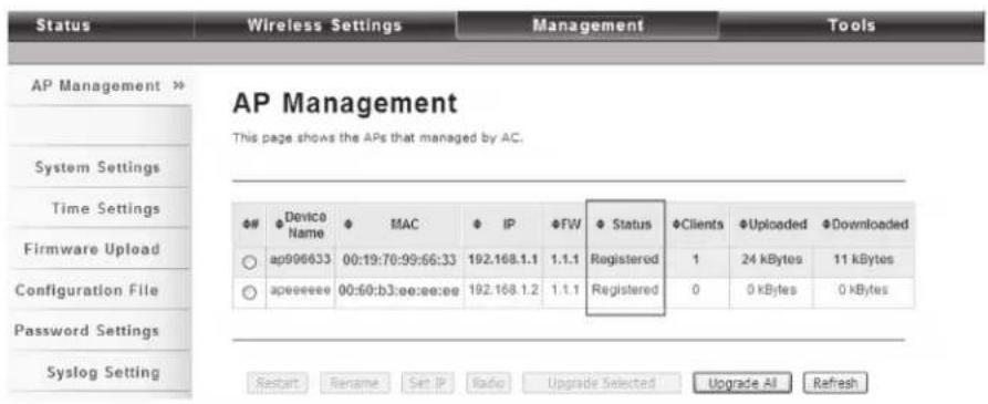
Figure 4-9. AP Management screen, Registered APs highlighted.
Moving the mouse over MAC address of each managed AP will also display relevant RF information such as channel mode, current channel, antenna being used, and transmit output power.
AP Management

Figure 4-10. AP Management screen, RF information.
4.5 Manage the extender-managed APs
To configure and manage the managed APs:
- Enter the web page of the Wireless Ethernet Extender in AC mode and go to Management —> AP Management. The following screen appears.

Figure 4-11. AP Management screen.
The Wireless Ethernet Extender AP in Virtual AC+Thin AP mode on the list is highlighted in bold font. Select it and press "Radio" to configure its radio setting, including channel bandwidth, channel, antenna, and output power.

Figure 4-12. AP Management screen, Radio button highlighted.
Besides radio setting, you may also reboot the managed AP, change its IP address, and upgrade the firmware for a managed AP.
4.6 Firmware Upgrade for the Ethernet Extender in AC mode
For firmware upgrade, you may choose to upgrade the selected managed AP by pressing "Upgrade Selected," or do the group upgrade by pressing "Upgrade All."
Before upgrading the managed AP, you need to locate the new firmware in the Wireless Ethernet Extender. Go to Management → Firmware Upload, browse the firmware file where it is located, click "Upload" and Click "OK."

Figure 4-13. Upgrade Firmware screen.
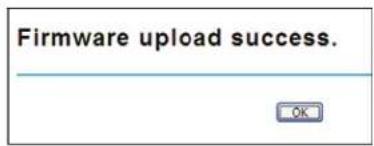
Figure 4-14. Upload Firmware screen.
Then go back to Management > AP Management to do single or group updates.

Figure 4-15. AP Management screen, Upgrade.
4.7 Monitor the Ethernet Extender-Managed AP
To view each managed AP's status, go to Status —> Managed APs. Besides viewing device information such as device name, MAC address, IP address, and FW version, you may also monitor the wireless clients that are currently associated with the managed APs as well as packets statistics.

Figure 4-16. Managed APs screen.
4.8 Configure the Fat AP mode
Fat AP mode operates as standalone AP that cannot be managed by the Wireless Ethernet Extender.
To switch from Virtual AC mode to Fat AP mode, go to Management —> System Settings. From the Device Mode drop-down list, select "Fat AP" and press "YES" to make the change take effect.

Figure 4-17. System settings.
To switch from default mode Thin AP to Fat AP mode for the first time configuration, go to Basic Settings. From the Device Mode drop-down list, select "Fat AP" and press "YES" to make the change take effect.
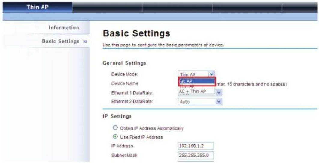
Figure 4-18. Basic Settings screen.
The Fat AP covers "AP mode," "Wireless Client mode," "Bridge mode," and "AP Repeater mode."
4.8.1 AP Mode
- Choose Wireless —> Basic Settings. The default is AP mode already. Here, you can set the parameters to optimize your application, or you can leave them as the default. Click "Apply" to save the parameters.
NOTE: In the example here, we only chaneg the "Wireless Network Name (SSID)" as "Join_me." In addition, for better coverage of the AP to optimize your WLAN network, use a high-gain external antenna. To allow the radio to calculate the EIRP and limit output to legal levels to comply with the regulation, you need to enter the Web GUI and specify the gain of the antenna after the external antenna is installed onto the access point.
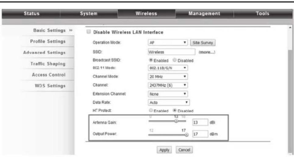
Figure 4-19. Dsiable Wireless LAN interface screen.
- If security is required, open Wireless —> Profile Setting and enter "VAP Profile 1 Settings" as below. You may set the parameters such as "Network Authentication" and "Data Encryption" for more secure network communication in your application. Click "Apply" to save the parameters.
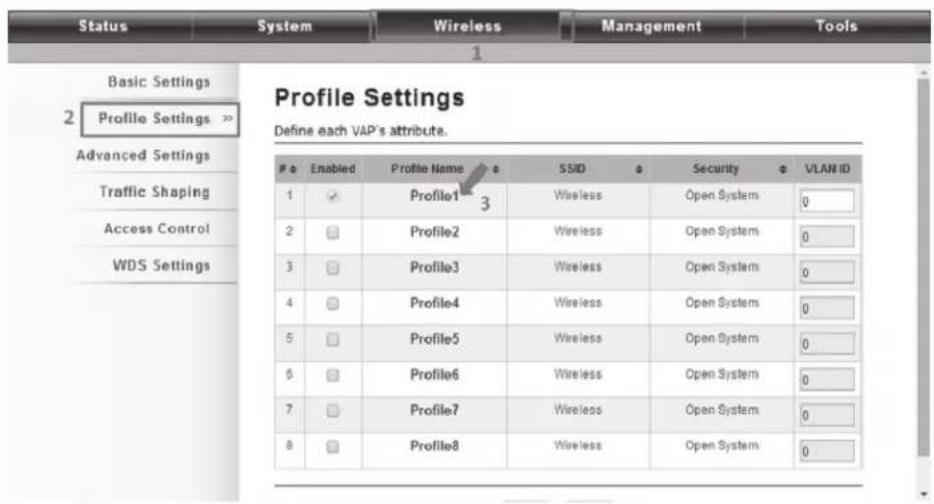
Figure 4-20. VAP Profile1 Settings screen.
- You may configure Network Authentication and Data Encryption parameters for more secure network communication in your application. After you configure these parameters, click "Apply" to save the parameters.

Figure 4-21. VAP1 Profile Settings screen.
- To decrease the chances of data retransmission at long distances, the extender can automatically adjust proper ACK timeout value by specifying the distance between the nodes. Go to Wireless —> Advanced Settings and fill in the number in the Distance field. If the distance is below 3280 feet (1000 meters), do not change it.

Figure 4-22. Advanced settings screen specifying distance.
4.8.2 Wireless Client Mode
- Choose Wireless —> Basic Settings. Then you will see the "Wireless Basic Settings" page. Choose "Wireless Client" from Wireless Mode, and click "Apply" to save it. You can then change the other parameters to optimize your application before clicking "Apply."

Figure 4-23. Basic Settings page.
- Click the "Site Survey" button beside Wireless Mode. It will scan all the available access points within coverage. Select the one you prefer to connect to, and click "Selected" to establish the connection.
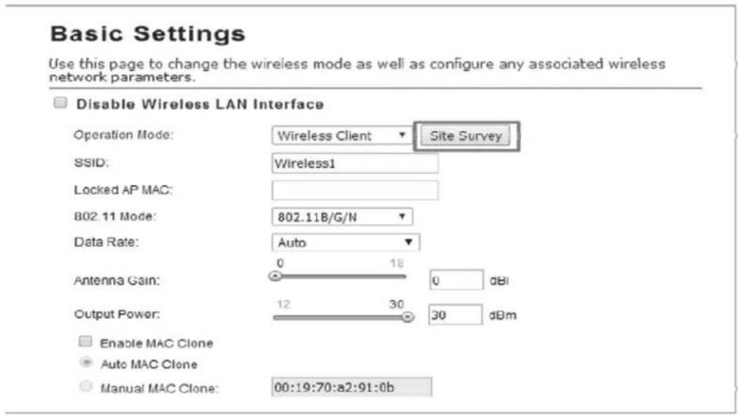
Figure 4-24. Select the preferred extender.
Wireless Site Survey
This page provides a tool to scan the wireless network.

Figure 4-25. Wireless Site Survey screen.
- If the AP you connect to require authentication or encryption keys, click "Profile Settings" in the left column, fill out the corresponding items, and click "Apply" for data encryption.
-
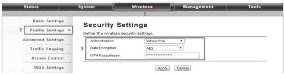
Figure 4-26. Security Settings screen.
- To check whether the association with the extender has been successfully made, go to Status —> Connections. If the connection is established, it will display association information including MAC addres, wireless mode, signal strength, and connection time.

Figure 4-27. Association list.
4.8.3 Bridge Mode
- Choose Wireless —> Basic Settings. Then you will see the "Wireless Basic Settings" page. Choose "Bridge" from Wireless Mode, and click "Apply" to save it. You can change the other parameters to optimize your application before clicking "Apply."

Figure 4-28. Wireless Basic Settings screen.
- Go to "WDS Settings" in "Wireless," type in the MAC address of the remote bridge to "Remote AP MAC Address 1" field and click "Apply."
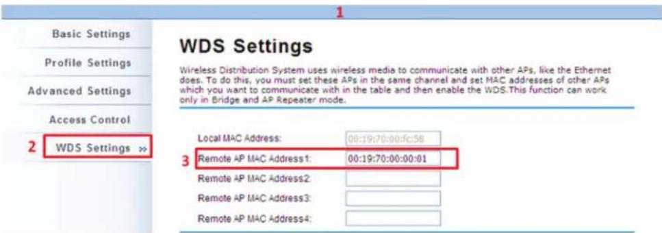
Figure 4-29. WDS Settings screen.
NOTE: The bridge uses the WDS protocol that is not defined as the standard, so compatibility issues between equipment from different vendors may arise. Moreover, Tree or Star shape network topology should be used in all WDS use-cases (i.e. if AP2 and AP3 are specified as the WDS peers of AP1, AP2 should not be specified as the WDS peer of AP3 and AP3 should not be specified as the WDS peer of AP2 in any case). Mesh and Ring network topologies are not supported by WDS, so do not use them.
-
Repeat the above procedures to configure the remote IEEE 802.11b/g/n Wireless Ethernet Extender.
-
Enter the actual distance in meters. For example, if the distance between the two VAC bridges is 3 kilometers, enter 3000 in the field.
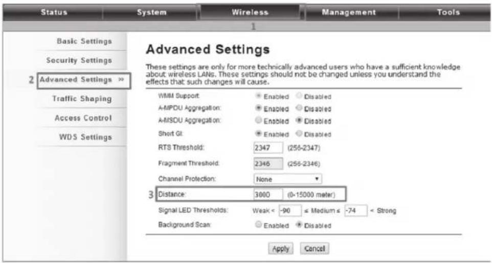
Figure 4-30. Advanced settings screen.
-
Use ping to check whether the link between the two bridges is OK.
-
To check the wireless connectivity, go to Status —> Connections. If the connection is established, it will display association information of the remote bridge, including MAC address, wireless mode, signal strength, and connection time.

Figure 4-31. Association list screen.
4.8.4 AP Repeater Mode
- Choose Wireless > Basic Settings. Choose "AP Repeater" from Wireless Mode, and click "Apply" to save it. You can also change the other parameters to optimize your application before clicking "Apply."

Figure 4-32. Wireless Basic Settings screen.
To establish a point-to-point bridge connection, follow the procedures described in Bridge mode. To connect the wireless client to the AP, follow the procedures described in Wireless Client mode.
5. Navigate the Web Configurator
5.1 Virtual AC+Thin AP Mode
5.1.1 Status
View Basic Information
Open "Information" in "Status" to check the basic information of the Wireless Ethernet Extender, which is read only. Information includes system information, IP settings, and wireless network setting. Click "Refresh" at the bottom of the page to display the real-time information.

Figure 5-1. Information screen.
View Managed APs
Open "Managed APs" in "Status" to check information of managed AP such as device name, MAC address, IP address, numbers of associated clients, and uploaded/downloaded packets. All options are read only. Click "Refresh" at the bottom of the page to update the list.
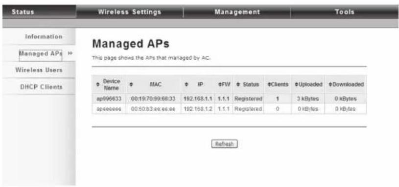
Figure 5-2. Managed APs screen.
View Wireless Users
Open "Wireless Users" in "Status" to check the information of all the wireless clients such as MAC address, SSID of the managed APs that are associated with, signal strength, connection up time, and uploaded/downloaded packets. All options are read only. Click "Refresh" at the bottom of the page to update the list.
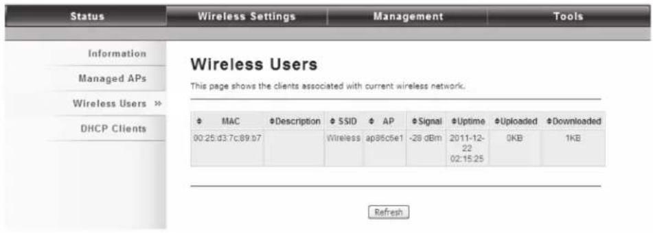
Figure 5-3. Wireless Users screen.
View DHCP Client Table
Open "DHCP Clients" in "Status" as shown next to check the assigned IP address, MAC address, and lease time for each DHCP client. Click "Refresh" to update the table.

Figure 5-4. DHCP Clients screen.
5.1.2 Wireless Settings
Wireless Settings allow you to configure wireless parameters, security method, access control, and flow control for your Wireless Ethernet Extender.
NOTE: The configuration will also apply on all the other VAC-managed APs.
Wireless Networks (VAP Profiles Settings)
The IEEE 802.11n VAC Access Point allows up to 8 virtual SSIDs on a single BSSID and to configure different profile settings such as security and VLAN ID to each SSID. To create a virtual AP, you may check the Enable box of the profile and click on the profile (eg. Profile 2) to configure wireless and security settings. Hit Apply to active the profile.

Figure 5-5. Wireless Networks screen.
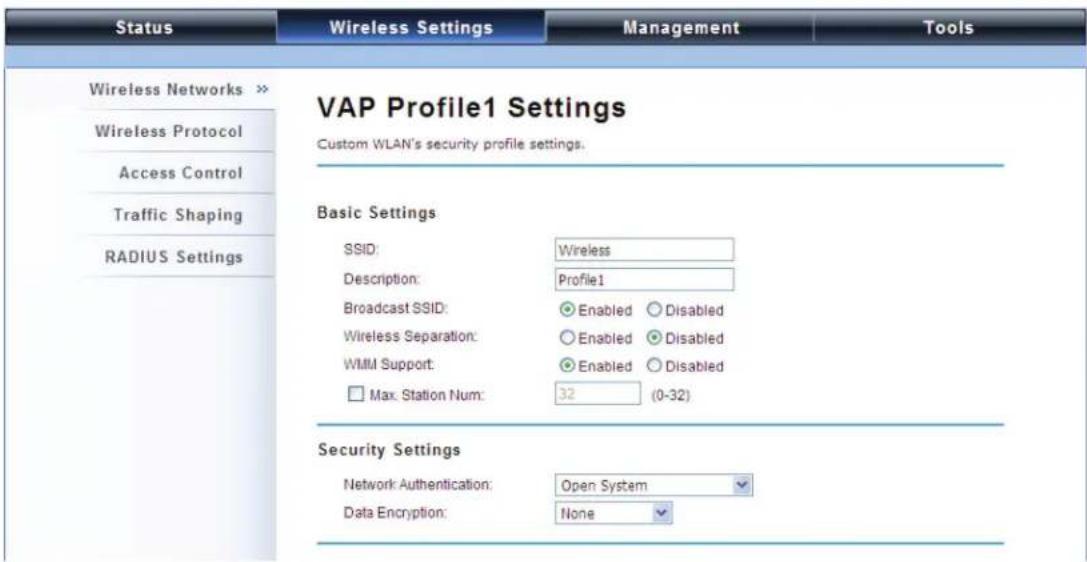
Figure 5-6. VAP Profile1 Settings screen.
Basic Setting
SSID: This wireless network name is shared among all associated devices in your wireless network. Keep it identical on all those devices.
NOTE: The SSID is case-sensitive and cannot exceed 32 characters.
Description: Name of the VAP profile
Broadcast SSID: In AP mode, hiding the network name is necessary when you are in a wireless environment that may have potential risk. By disabling broadcast SSID, the STA cannot scan and find the Wireless Ethernet Extender, so that malicious attack by an illegal STA can be avoided.
Wireless Separation: Wireless separation is an ideal way to enhance the security of network transmission. Enabling “Wireless Separation” can prevent the communication among associated wireless clients.
WMM Support: WMM (Wi-Fi Multimedia) is a subset of 802.11e. It allows wireless communication to define a priority limit on the basis of data type under AP mode only, thus those time-sensitive data, like video/audio data, may own a higher priority than common ones. To enable WMM, the wireless client should also support it. By default, it is enabled and cannot be disabled in b/g/n mode.
Max. Station Number: By default the "Max. Station Num" the VAC Access Point will only allow up to 32 wireless clients to associate with for better bandwidth for each client. Tick the box and enter the preferable limits for maximum client association number.
Security Setting
To prevent unauthorized radios from accessing data transmitting over the connectivity, the IEEE 802.11a/n VAC Access Point provides you with rock-solid security settings.
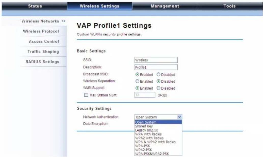
Figure 5-7. VAP Profile1 Settings screen.
Network Authentication
Open System: Allows any device to join the network without performing any security check.
Shared Key: Data encryption and key are required for wireless authentication (Not available in Bridge/AP Repeater mode).
Legacy 802.1x: Provides the rights to access the wireless network and wired Ethernet. With User and PC identity, centralized authentication as well as dynamic key management, it reduces the security risk. To serve the 802.1x, at least one EAP type should be supported by the RADIUS Server, AP and wireless client.
WPA with RADIUS: Wi-Fi Protected Access (WPA) is a subset of the IEEE 802.11i standard. With warrant (username, password and etc.) offered by user, this kind of authentication can be realized with specific RADIUS server. This is the common way to be adopted in large enterprise network.
WPA2 with RADIUS: WPA2 (IEEE 802.11i) is a wireless security standard that defines stronger encryption, authentication and key management than WPA. If it is selected, AES encryption and RADIUS server are required.
WPA&WPA2 with RADIUS: It provides options of WPA (TKIP) or WPA2 (AES) for the client. If it is selected, the data encryption type must be TKIP + AES and the RADIUS server must be set.
NOTE: If Radius-relevant authentication type is selected, go to Wireless—>Radius Settings for further radius server configuration.
WPA-PSK: It is a simplified WPA mode with no need for specific authentication server. In this so-called WPA Pre-Shared Key, all you have to do is just pre-enter a key in each WLAN node. This is commonly used in large and middle enterprise, as well as residential networks.
WPA2-PSK: As a new version of WPA, only all the clients support WPA2, can it be available. If it is selected, the data encryption can only be AES and the passphrase is required.
WPA-PSK&WPA2-PSK: Available in AP mode, it provides options of WPA (TKIP) or WPA2 (AES) encryption for the client. If it is selected, the data encryption can only be TKIP + AES and the passphrase is required.
Data Encryption
If data encryption is enabled, the key is required and other wireless devices can communicate only if they share the same key.
None: Available only when the authentication type is open system.
64 bits WEP: It is made up of 10 hexadecimal numbers.
128 bits WEP: It is made up of 26 hexadecimal numbers.
152 bits WEP: It is made up of 32 hexadecimal numbers.
TKIP: Temporal Key Integrity Protocol, which is a kind of dynamic encryption, is used with WPA-PSK, etc.
AES: Advanced Encryption Standard, it is commonly used with WPA2-PSK, WPA, WPA2, etc.
TKIP + AES: It allows for backwards compatibility with devices using TKIP.
NOTE: We strongly recommend you enable wireless security on your network!
NOTE: Only Wireless Ethernet Extenders and wireless clients with the same Authentication, Data Encryption, and Key can communicate.
Network Basic Setting

Figure 5-8. Network Basic Setting screen.
Network Mode: Specify the network mode. It includes Bridge and Router. When switched to Router mode, the LAN IP address for web page access will become 192.168.0.99.
Wireless Protocols
Allows the user to change country code, 802.11 mode and other advanced parameters for the Wireless Ethernet Extender.

Figure 5-9. Wireless Basic Settings screen.
Basic Settings
Country Region: The availability of some specific channels and/or operational frequency bands is country-dependent.
802.11 Mode: The IEEE 802.11n VAC Access Point can communicate with wireless devices using 802.11b/g or 802.11b/g/n.
Data Rate: Usually "Auto" is preferred. Under this rate, the IEEE 802.11n VAC Access Point will automatically select the highest available rate to transmit. In some cases, for example where there is no great demand for speed, you can set a relatively low transmit rate and get longer distance.
Advanced Settings
| Status | Wireless Settings | Management | Tools |
| Wireless Networks | Country/Region: | United States | |
| 802.11 Mode: | 802.11A/B/G/N | ||
| Wireless Protocol >> | Data Rate: | Auto | |
| Access Control | Advanced Settings | ||
| Traffic Shaping | A-MPDU Aggregation: | Enabled Disabled | |
| A-MSDU Aggregation: | Enabled Disabled | ||
| Short GI: | Enabled Disabled | ||
| IGMP Snooping: | Enabled Disabled | ||
| RIFS: | Enabled Disabled | ||
| HT Protect: | Enabled Disabled | ||
| Preamble Type: | Long Auto | ||
| RTS Threshold: | 2347 (1-2347) | ||
| Fragment Threshold: | 2346 (256-2346) | ||
| Beacon Interval: | 100 (20-1024 ms) | ||
| DTIM Interval: | 1 (1-255) | ||
| Extension Channel Protection: | None | ||
| Space In Meter: | 1000 (0-15000 m) | ||
| Link Integration: | Enabled Disabled | ||
| TDM Coordination: | Enabled Disabled | ||
Figure 5-10. Advanced Settings screen.
A-MPDU/A-MSDU Aggregation: The data rate of your AP except wireless client mode could be enhanced greatly with this option enabled; however, if your wireless clients don't support A-MPDU/A-MSDU aggregation, we do not recommend enabling it.
Short GI: Under 802.11n mode, enables better data rate if there is no negative compatibility issue.
IGMP Snooping: IGMP snooping is the process of listening to IGMP network traffic. By enabling IGMP snooping, the AP will listen to IGMP membership reports and queries, and leave messages to identify the ports that are members of multicast groups. Multicast traffic will only be forwarded to ports identified as members of the specific multicast group.
RIFS: RIFS (Reduced Interframe Spacing) reduces overhead and thereby increases network efficiency.
HT Protect: Enable HT (High Throughput) protect to ensure HT transmission with MAC mechanism. Under 802.11n mode, wireless client can be divided into HT STA and Non-HT STA, among which the one with HT protect enabled gets higher throughput.
Preamble Type: It defines some details on the 802.11 physical layer. "Long" and "Auto" are available.
RTS Threshold: The Wireless Ethernet Extender sends RTS (Request to Send) frames to certain receiving stations and negotiates the sending of a data frame. After receiving an RTS, that STA responds with a CTS (Clear to Send) frame to acknowledge the right to start transmission. The setting range is 0 to 2346 bytes. Setting it too low may result in poor network performance. Leave We recommend using the default setting, 2346.
Fragmentation Threshold: Specify the maximum size in byte for a packet before data is fragmented into multiple packets. Setting it too low may result in poor network performance. Leave it at its default of 2346 is recommended.
Beacon Interval: Specify the frequency interval to broadcast packets. Enter a value between 20 and 1024.
DTIM Interval: DTIM, which stands for Delivery Traffic Indication Message, is contained in the data packets. It is for enhancing the wireless transmission efficiency. The default is set to 1. Enter a value between 1 and 255.
Channel Protection Mode: This is to avoid conflict with other wireless network and boost the ability of your device to catch all 802.11g transmissions. However, it may decrease wireless network performance. Compared to CTS-Self; the transmission amount of CTS-RTS is much lower.
Distance: To decrease the chances of data retransmission at long distance, the Wireless Ethernet Extender can automatically adjust proper ACK timeout value by specifying distance of the two nodes.
Access Control
The Access Control appoints the authority to wireless client for accessing the Wireless Ethernet Extender, thus a further security mechanism is provided. This function is available only under AP/Router mode.
Open "Access Control" in "Wireless Settings" as shown next.
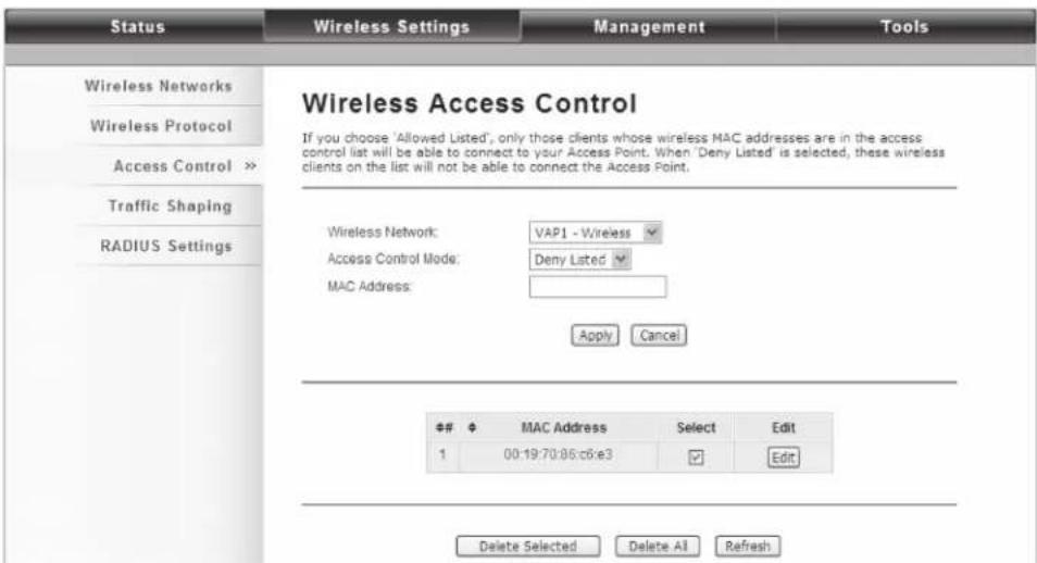
Figure 5-11. Wireless Access Control screen.
Wireless Network: Select the VAP network you would like to enable access control.
Access Control Mode
If you select "Allow Listed", only those clients whose wireless MAC addresses are in the access control list will be able to connect to your AP. When "Deny Listed" is selected, those wireless clients on the list will not be able to connect the AP.
MAC Address
Enter the MAC address of the wireless client that you would like to list into the access control list, click "Apply" then it will be added into the table at the bottom.
Delete Selected/All
Check the box before one or more MAC addresses of wireless client(s) that you would like to cancel, and click "Delete Selected" or "Delete All" to cancel that access control rule.
Traffic Shaping
This allows the administrator to manage the traffic flow to ensure optimal performance.
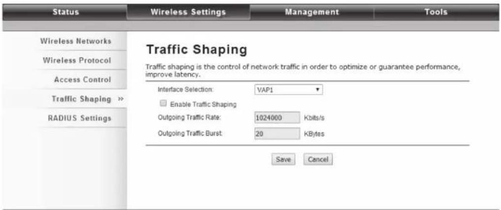
Figure 5-12. Traffic Shaping screen.
Enable Traffic Shaping
Check this box to control the overall bandwidth for a specific VAP network.
Interface Selection
Select the VAP network you would like to enable traffic shaping.
Outgoing Traffic Rate
This specifies maximum outgoing bandwidth to a certain rate in kbps.
Outgoing Traffic Burst
This specifies the buffer size for outgoing traffic that can be sent within a given unit of time. The suggested value is 20 KB. You may just leave the default value there, and then the connection will be bound to the traffic shaping rule at all times. You may decrease it to smaller value if the incoming traffic limit is smaller.
Radius Settings
RADIUS (Remote Authentication Dial-In User Service) is a server for remote user authentication and accounting; it plays a central role in the network in providing the capabilities of authenticating, authorizing, accounting, auditing, alarming, and etc. It allows an organization to maintain user profiles in a central database that all remote servers can share. If 802.1X, WPA(2) is used, you need to configure radius settings.
Go to "RADIUS Settings" in "Wireless Settings" to make RADIUS configuration.

Figure 5-13. RADIUS Settings.
Authentication RADIUS Server
This is for RADIUS authentication. It can communicate with RADIUS through IP Address, Port, and Shared Secret.
IP Address: Enter the IP address of the Radius Server;
Port: Enter the port number of the Radius Server;
Shared Secret: This secret, which is composed of no more than 31 characters, is shared by the Wireless Ethernet Extender and RADIUS during authentication.
Global-Key Update
Check this option and specify the time interval between two global-key updates. Default is 3600 seconds.
TCP/IP Settings
When the Router mode is activated, the TCP/IP Settings will show up in Wireless Settings so the user can configure the TCP/IP for the VAC-managed Access Point.

Figure 5-14. TCP/IP Settings screen.
LAN Settings
IP Address: Specify the IP address for the Wireless Ethernet Extender.
Subnet Mask: Specify the Subnet mask for the Wireless Ethernet Extender .
DHCP Server: Select to enable or disable DHCP server on the Wireless Ethernet Extender.
DHCP IP Address Range: When the DHCP Server is enabled, users may specify DHCP IP Address Range for the Wireless Ethernet Extender .
DHCP Subnet Mask: Specify the DHCP Subnet Mask for the Wireless Ethernet Extender.
Lease Time: Specify the lease time (15–44640 minutes) for the Wireless Ethernet Extender
NOTE: For wireless clients who want to access the unit's web page in Router mode, type the IP address here in the browser's address bar to enter the web page.
Captive Portal
Captive portal is a management which allows WLAN users to easily and securely access the Internet. Under Router mode, when captive portal is enabled, the IEEE 802.11n VAC Access Point will redirect the client to go to an authentication web page before browsing Internet web pages. Captive portals are used on most Wi-Fi hotspots networks. Therefore, to use captive portal, you need to find the service providers that have the additional services needed to make captive portal work.

Figure 5-15. Captive Portal screen.
To enable Captive Portal, check "Captive Portal" and select the VAP network needed for captive portal.
Radius Settings
Primary Radius Server: Enter the name or IP address of the primary radius server.
Secondary Radius Server: Enter the name or IP address of the secondary radius server if any.
Radius Auth Port: Enter the port number for authentication.
Radius Acct Port: Enter the port number for billing.
Radius Shared Secret: Enter the secret key of the radius server.
Radius NAS ID: Enter the name of the radius server if any.
Radius Administrative-User
Radius Admin Username: Enter the username of the Radius Administrator.
Radius Admin Password: Enter the password of the Radius Administrator.
Captive Portal
UAM Portal URL: Enter the address of the UAM portal server.
UAM Secret: Enter the secret password between the redirect URL and the Hotspot.
Firewall Settings
The firewall is a system or group of systems that enforce an access control policy between two networks. It may also be defined as a mechanism used to protect a trusted network from an un-trusted network. The Wireless Ethernet Extender uses Source IP Filtering, Destination IP Filtering, Source Port Filtering, Destination Port Filtering, and Port Forwarding, as well as DMZ. This is available only under Router Mode.
Source IP Filtering

Figure 5-16. Source IP Filtering screen.
You may create and activate a rule that filters a packet based on the source IP address from your local network to Internet. Check "Enable Source IP Filtering" to activate rule.
Local IP Address: Enter the IP address you would like to restrict.
Comment: Make comments to record your filtering rule.
Click Apply and the IP address will be added in the list. To delete the IP address from filtering, click Select checkbox of the designated IP address and click the Delete Selected button. You may delete all the IP addresses in the list by clicking Delete All.
Destination IP Filtering
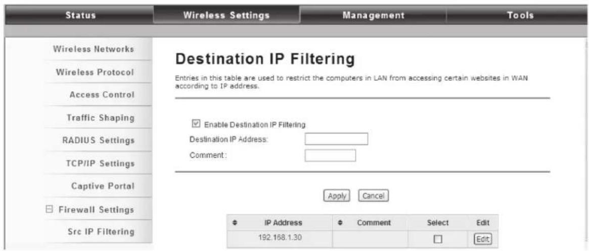
Figure 5-17. Destination IP Filtering screen.
You may create and activate a rule that filters a packet based on the destination IP address to restrict the local computers from accessing certain websites. Check "Enable Destination IP Filtering" to activate rule.
Destination IP Address: Enter the IP address to be restricted.
Comment: Make comments to record your filtering rule.
Click Apply and the IP address will be added in the list. To delete the IP address from filtering, click Select checkbox of the designated destination IP address and click the Delete Selected button. You may delete all the IP addresses in the list by clicking Delete All.
Source Port Filtering

Figure 5-18. Source Port Filtering screen.
You may create and activate a rule that filters a packet based on the source port from your local network to Internet. Check "Enable Source Port Filtering" to activate rule.
Port Range: Enter the port range you would like to restrict.
Protocol: Select port protocol: Both, TCP, UDP.
Comment: Make comments to record your filtering rule.
Click Apply and the IP address will be added in the list. To delete the restricted source ports, click Select checkbox of the designated ports and click the Delete Selected button. You may delete all the IP addresses in the list by clicking Delete All.
Destination Port Filtering
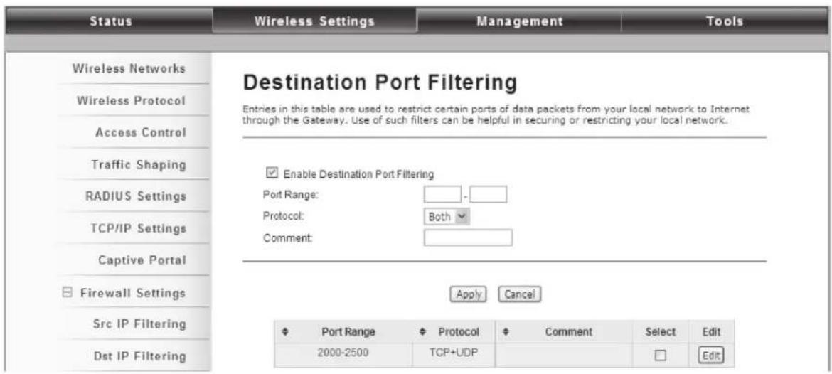
Figure 5-19. Destination Port Filtering screen.
You may create and activate a rule that filters a packet based on the destination port from your local network to Internet. Check "Enable Destination Port Filtering" to activate rule.
Port Range: Enter the port range you would like to restrict.
Protocol: Select port protocol: Both, TCP, UDP.
Comment: Make comments to record your filtering rule.
Click Apply and the IP address will be added in the list. To delete the restricted destination ports, click Select checkbox of the designated ports and click the Delete Selected button. You may delete all the IP addresses in the list by clicking Delete All.
Port Forwarding
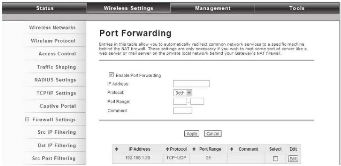
Figure 5-20. Port Forwarding screen.
Port forwarding allows you to automatically redirect common network services to a specific machine behind the NAT firewall. These settings are only necessary if you wish to host some a server such as a web server or mail server on the private local network behind the Wireless Ethernet Extender NAT firewall.
5.1.3 Management
The Wireless Ethernet Extender can manage up to 50 VAC-managed APs. The Wireless Ethernet Extender provides thin AP management for editing the VAC-managed AP settings, upgrading the firmware, and monitoring, etc.
AP Management
AP Management allows you to configure and upgrade the VAC-managed APs. Select the VAP-managed AP you would like to specifically configure.

Figure 5-21. AP Management screen.
Restart: Restart the selected VAC-managed AP.
Rename: Rename the selected VAC-managed AP.
Set IP: Assign a static IP address for the selected VAC-managed AP or obtain the IP address from the Wireless Ethernet Extender in AC mode. Default is DHCP client.

Figure 5-22. DHCP Client/Static IP screen.
Radio: Allows you to configure the channel bandwidth, operating channel, antenna, and output power for the selected VAC-managed Access Point.

Figure 5-23. Radio channel screen.
From the AP Management list, move the mouse cursor to the MAC address of the selected VAC-managed AP the screen will pop up radio configuration information.
AP Management
AP Management
This page shows the APs that managed by AC.

Figure 5-24. AP Management screen.
Upgrade Selected: Upgrade firmware for the selected Wireless Ethernet Extender.
NOTE: You need to upload the firmware file into the Wireless Ethernet Extender mode before upgrading firmware; otherwise, a window will pop up saying TAP firmware hasn't been uploaded.

Figure 5-25. TAP Firmware prompt.
Upgrade All: Click to upgrade all the VAC-managed APs simultaneously.
Refresh: Refresh the AP management list manually.
System Settings
Allows you to configure device and IP settings for the Wireless Ethernet Extender in AC mode.
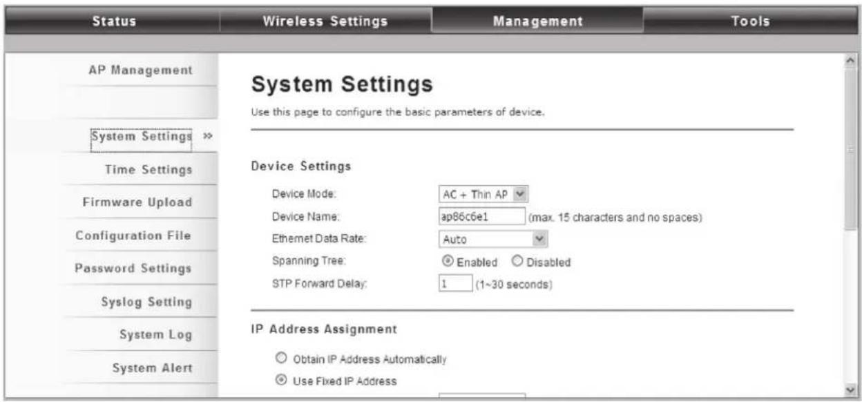
Figure 5-26. System Settings screen.
Device Settings
Device Mode: Three modes are provided: AC+Thin AP, Thin AP, and FAT AP. Select AC+Thin AP to have the device act as a virtual access controller to manage other VAC-managed APs on your network. Select "Thin AP" to have the VAC Access Point managed by the VAC AP in AC mode. Select FAT AP to perform as a standalone AP, neither managing nor managed by other VAC APs.
Device Name: Specify the device name, which is composed of no more than 15 characters with (0-9), (A-Z), (a-z) or (-).
Ethernet Data Rate: Specify the transmission rate of data for Ethernet. Default is Auto.
Spanning Tree: Spanning Tree Protocol (STP) is a link management protocol for AP which provides path redundancy while preventing loops in a network. STP allows only one active path at a time between the access points but establishes the redundant link as a backup if the initial link fails.
STP Forward Delay: STP Forward Delay is the time spent in detecting and learning network tree topology state before entering the forward state. Default time value is 1 sec.
IP Address Assignment
IP Address Assignment
Obtain IP Address Automatically
Use Fixed IP Address
IP Address:
192.168.1.100
Subnet Mask:
255.255.255.0
Gateway Ip Address:
0.0.0.0
DNS 1:
0.0.0.0
DNS 2:
0.0.0.0
Figure 5-27. IP Address Assignment screen.
Obtain IP Address Automatically: If a DHCP server exists in your network, you can check this option, so the IWireless Ethernet Extender can obtain IP settings automatically from the DHCP server.
Use Fixed IP Address: Check this option. You have to specify a static IP address, subnet mask, default gateway and DNS server for the Wireless Ethernet Extender manually. Make sure the specified IP address is unique on your network in order to prevent IP conflict.
DHCP Server
The Wireless Ethernet Extender in AC mode can perform a DHCP server to assign IP address to the VAC-managed APs. Default is enabled.
DHCP Server
DHCP IP Address Range:
192.168.1.2
192.168.1.200
DHCP Subnet Mask:
255.255.255.0
DHCP Gateway:
0.0.0.0
Lease Time:
7200
(15-44640 Minutes)
Figure 5-28. DHCP Server screen.
DHCP IP Address Range: Specify the IP range.
DHCP Subnet Mask: Specify the DHCP Subnet Mask.
DHCP Gateway: Specify the gateway address.
Lease Time: Specify the DHCP lease time.
Time Settings
Compliant with NTP, the IEEE 802.11n VAC Access Point is capable of keeping its time in complete accord with the Internet time. To use this feature, check "Enable NTP Client Update" in advance.
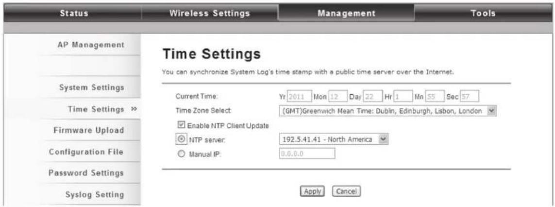
Figure 5-29. Time Settings screen.
Current Time
Display the present time in Yr, Mon, Day, Hr, Min and Sec.
Time Zone Select
Select the time zone from the dropdown list.
NTP Server
Select the time server from the "NTP Server" dropdown list. or manually input the IP address of available time server into "Manual IP".
Firmware Upgrade
Besides upgrading firmware for the Wireless Ethernet Extender in AC mode, it also provides firmware update for the VAC-managed APs.
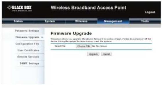
Figure 5-30. Upgrade Firmware screen.
Upload AC Firmware
Allows the network administrator to upgrade firmware for the Wireless Ethernet Extender in AC mode.
Upload TAP Firmware
Before updating the firmware for the VAC-managed APs, you need to upload the firmware into the VAC Access Point in AC mode that allows the virtual controller AP to do the firmware upgrade for VAC-managed APs.
CAUTION: Do NOT cut the power off during upgrade; otherwise, the system may crash!
Backup/ Retrieve Settings
We strongly recommend you back up configuration information in case of something unexpected. If tragedy hits your device, you may have access to restore the important files by the backup. All these can be done by the local or remote computer.

Figure 5-31. Backup configuration screen.
Save AC Settings to File
Click Save to export the configuration file of the Wireless Ethernet Extender in AC mode. Then the configuration file ac.cfg will be generated and saved to the specified location.
Save TAP Settings to File
Click Save to export the configuration file of the Wireless Ethernet Extender. Then the configuration file tap.cfg will be generated and saved to the specified location.
Load Settings from File
Import ac.cfg load into the VAC Access Point in AC mode.
Restore Factory Default Settings
The IEEE 802.11n VAC Access Point provides two ways to restore the factory default settings:
Restore factory default settings via Web
From Configuration File in Management, click Reset restore factory default settings.

Figure 5-32. Configuration file screen.
Restore factory default settings via Reset Button
If software in the Wireless Ethernet Extender unexpectedly crashes and you can no longer reset the unit via Web, you may do a hardware reset via the reset button. Press and hold the button for at least 5 seconds and then release it until the PWR LED blinks. The hardware reset will take about 2 minutes to complete.
Reboot
You can software reboot your Wireless Ethernet Extender from Configuration File in Management as described next:

Figure 5-33. Rebooting from the Configuration screen.
Click "Reboot" and click "Yes" when prompt appears to start reboot process. This takes a few minutes.
Password Settings
You can change the password for your Wireless Ethernet Extender.

Figure 5-34. Password Settings screen.
Current Password
Enter the current password.
New Password
Enter the new password.
Confirm Password
Enter the new password again for confirmation.
NOTE: The password is case-sensitive and its length cannot exceed 19 characters!
Syslog Settings
The Wireless Ethernet Extender provides remote syslog management by sending logs to an external syslog server. The log can be also sent through Email.

Figure 5-35. Syslog Settings screen.
Remote Syslog Server
Enable Remote Syslog: Enable to send log to remote syslog server.
IP Address: Specify the IP address of the remote server.
Port: Specify the port number of the remote server.
Send Syslog via Email
Log Schedule: Configure the frequency of logs being sent. Five scheduling options are provided: Never, Hourly, Daily, Weekly, and When log is full.
Severity Level: Choose All to send all the logs or Alert to send only the alert messages.
Send Log to: Specify the email address where you would like to send the log.
Day for Sending Log: When Weekly scheduling is selected, you may specify which week day to send the log.
Time for Sending Log: Specify the time of the day to send the log.
Clear Log: To clear log after sending logs via email, check the After Sending Mail checkbox.
Mail Server Setting
Send Log From: Enter the email address of the mail server.
Mail Subject: Type a title to be presented in the subject line of the log email message.
SMTP Server: Enter the IP address of the SMTP sever.
SMTP Authentication: If you want to use SMTP authentication, check SMTP Authentication checkbox and enter the user account and password.
System Log
System log record and display all logs and alert message in this page. Once the log entries are all used, the log will wrap around and the old logs will be deleted. You may click Clear to delete logs manually as well.
| Status | Wireless Settings | Management | Tools | ||||
| AP Management System Log This page show the system log. | |||||||
| Time Settings Time | Priority | Source | Message | ||||
| 1 | 2011-12-22 00:55:05 | info | 192.168.1.100 | znmpd: AC started. | |||
| 2 | 2011-12-22 00:55:06 | alert | 00:19:70:86:C6:E1 | WLAN service started. | |||
| 3 | 2011-12-22 00:55:06 | alert | 00:19:70:86:C6:E1 | WLAN service stopped. | |||
| 4 | 2011-12-22 00:55:06 | alert | 00:19:70:86:C6:E1 | WLAN service started. | |||
| 5 | 2011-12-22 00:55:11 | alert | 192.168.1.100 | znmpd: Device connected. | |||
| 6 | 2011-12-22 00:55:12 | notice | 192.168.1.111 | WEB: Authorized user "admin". | |||
| 7 | 2011-12-22 00:55:41 | alert | 192.168.1.2 | znmpd: Device connected. | |||
| 8 | 2011-12-22 01:36:47 | alert | 00:60:B3:11:22:33 | Station reassociated. | |||
| 9 | 2011-12-22 01:39:47 | alert | 00:60:B3:11:22:33 | Station deauthenticated. | |||
| 10 | 2011-12-22 02:15:06 | notice | 192.168.1.111 | WEB: User "admin" logout. | |||
Figure 5-36. System Log screen.
System Alert
System alert record and events occurred on both Wireless Ethernet Extender in AC mode and VAC-managed AP in this page. Once the log entries are all used, the log will wrap around and the old logs will be deleted. Click Clear to delete logs manually as well.

Figure 5-37. System Alert screen.
5.1.4 Tools
The IEEE 802.11n VAC Access Points provide two tools to test the link status with other VAC-managed Access Points or anyone on the network.
Ping

Figure 5-38. Ping screen.
Ping Address
Enter IP address of the remote destination.
Ping Count
Enter the number of pings.
Packet Size
Specify ping packet size.
Trace Route
This tool is used to discover the routes that packets take when traveling to the destination destination.
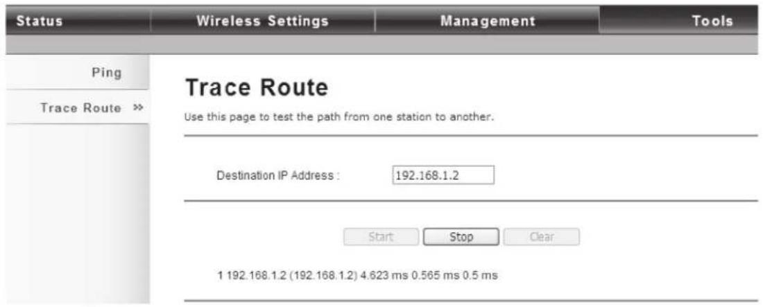
Figure 5-39. Trace Route screen.
Destination IP Address
Enter IP address of the remote destination and click Start to start.
5.2 Thin AP Mode
5.2.1 Information
You may see some VAC-managed AP's basic information such as model name, firmware version, MAC address, current up time, registration status as well as MAC address.

Figure 5-40. Information screen.
5.2.2 Basic Settings
Allows you to configure device and IP settings for the VAC-managed AP.

Figure 5-41. Basic Settings screen.
General Settings
Device Mode: Three modes are provided: AC+Thin AP, Thin AP, FAT AP. Select AC+Thin AP to have the device act as virtual access controller to manage other VAC-managed APs on your network. Select "Thin AP" to have the VAC Access Point managed by the VAC AP in AC mode. Select FAT AP to perform as a standalone AP, neither managing nor managed by other VAC APs.
Device Name: Specify the device name, which is composed of no more than 15 characters with (0-9), (A-Z), (a-z) or (-).
Ethernet Data Rate: Specify the transmission rate of data for Ethernet. Default is Auto.
IP Address Assignment
Obtain IP Address Automatically: If a DHCP server exists in your network, you can check this option, thus the IEEE 802.11n VAC Access Pioint is able to obtain IP settings automatically from the DHCP server.
Use Fixed IP Address: Check this option. You have to specify a static IP address, subnet mask, default gateway and DNS server for the VAC Access Point manually. Make sure the specified IP address is unique on your network in order to prevent IP conflict.
Enable 802.1Q VLAN
To be able to access the web page of the VAC-managed AP in the VLAN network, you need to assign the VLAN management ID for the VAC-managed AP. Note that the ID on the switch must be identical of the AP's VLAN ID. Check Enable 802.1Q VLAN checkbox to activate it.
Management VLAN ID: Enter the VLAN ID.
5.3 FAT AP Mode
5.3.1 Status
View Basic Information
Open "Information" in "Status" to check the basic information of the Wireless Ethernet Extender, which is read only. Information includes system information, LAN settings, wireless setting, and interface status. Click "Refresh" at the bottom for real-time information.
| Information » | |
| Connections | Information This page shows the current status and some basic settings of the device. |
| Statistics | System Information |
| ARP Table | Device Name ap86c6e1 |
| Bridge Table | MAC Address 00:19:70:86:c6:e1 |
| Country/Region United States | |
| DHCP Clients | Firmware Version 1.1.1 |
| Network Activity | LAN Settings |
| IP Address 192.168.1.100 | |
| Subnet Mask 255.255.255.0 | |
| Gateway IP Address 0.0.0.0 | |
| MAC Address 00:19:70:86:c6:e1 | |
| Wireless Settings | |
| Operation Mode AP | |
| Wireless Mode 802.11B/G/N | |
Figure 5-42. Information screen.
View Association List
Open "Connections" in "Status" to check the information of associated wireless devices such as MAC address, signal strength, connection time, IP address, etc. All options are read only. Click "Refresh" at the bottom to update the current association list.

Figure 5-43. Association List.
By clicking on the MAC address of the selected device on the web, you may see more details including device name, connection time, signal strength, noise floor, ACK timeout, link quality, IP information, current data rate, and current TX/RX packets.
Association Node Details
The details information of association node:
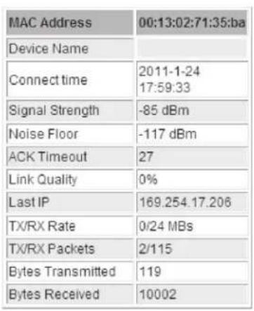

Figure 5-44. Association Node Details screen.
View Network Flow Statistics
Open "Statistics" in "Status" to check the data packets received on and transmitted from the wireless and Ethernet ports. Click "Refresh" to view current statistics.

Figure 5-45. Statistics screen.
Poll Interval
Specify the refresh time interval in the box beside "Poll Interval" and click "Set Interval" to save settings. "Stop" helps to stop the auto refresh of network flow statistics.
View ARP Table
Open "ARP Table" in "Status" as below. Click "Refresh" to view current table.
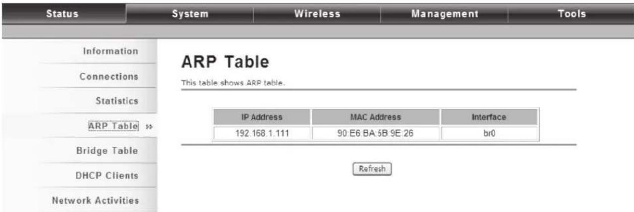
Figure 5-46. ARP Table screen.
View Bridge Table
Open "Bridge Table" in "Status" as shown next. Click "Refresh" to view current connected status.
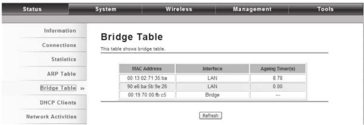
Figure 5-47. Bridge Table screen.
View Active DHCP Client Table
Open "DHCP Clients" in "Status" as shown next to check the assigned IP address, MAC address, and time expired for each DHCP leased client. Click "Refresh" to view the current table.

Figure 5-48. DHCP Clients screen.
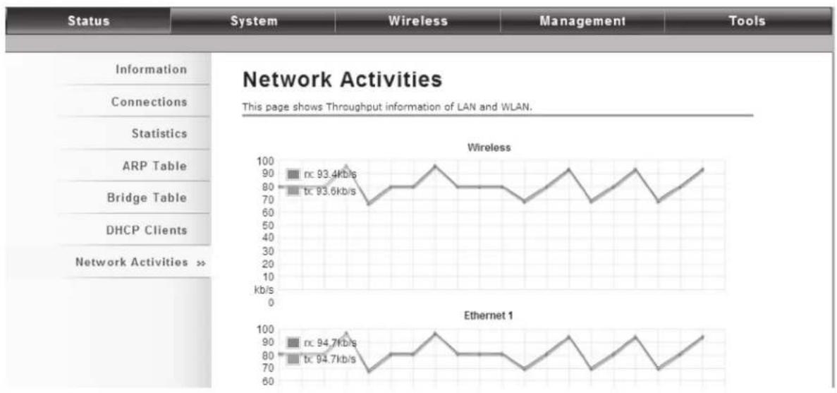
View Network Activities
The network activities allows you to monitor the current Wireless and Ethernet TX/RX data traffic in graphical and numerical form on the Web of the Skyport. The chart scale and throughput dimension (Bps, Kbps, Mbps) changes dynamically according to the mean throughput value. Throughput statistics can be updated manually using the "Refresh" button.
line
| System | Wireless (kb/s) | Ethernet 1 (kb/s) | | -------------- | --------------- | ----------------- | | Information | 93.4 | 94.7 | | Connections | 93.6 | 94.7 |Figure 5-49. Network Activities screen.
5.3.2 System
Basic System Settings
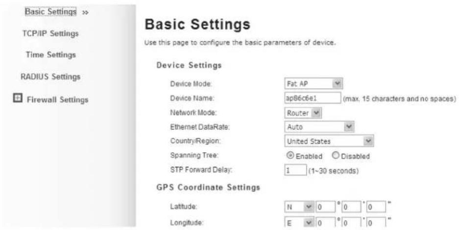
Figure 5-50. Basic Settings screen.
Device Settings
Device Mode: Three modes are provided: AC+Thin AP, Thin AP, FAT AP. Select AC+Thin AP to have the device act as virtual access controller to manage other VAC-managed APs on your network. Select "Thin AP" to have the VAC Access Point managed by the VAC AP in AC mode. elect FAT AP to perform as a standalone AP, neither managing nor managed by other VAC APs.
Device Name: Specify the device name, which is composed of no more than 15 characters with (0-9), (A-Z), (a-z) or (-).
Network Mode: Specify the network mode, including Bridge and Router. It is easy to configure parameters in Bridge Mode; however, users must pay extra attention to the way they configure the device when it is set to Router Mode. For details, please refer to TCP/IP Settings.
Ethernet Data Rate: Specify the transmission rate of data for Ethernet. Default is Auto.
Country Region: The availability of some specific channels and/or operational frequency bands is country dependent.
Spanning Tree: Spanning Tree Protocol (STP) is a link management protocol for AP which provides path redundancy while preventing loops in a network. STP allows only one active path at a time between the access points but establish the redundant link as a backup if the initial link fails.
STP Forward Delay: STP Forward Delay is the time spent in detecting and learning network tree topology state before entering the forward state. Default time value is 1 sec.
GPS Coordinate Settings
The GPS Coordinate Setting helps you mark the latitude and longitude of the Wireless Ethernet Extender. Just enter the coordinates and click the Apply button.
TCP/IP Settings
Open "TCP/IP Settings" in "System" as shown next to configure the parameters for the LAN that connects to the LAN port of the Wireless Ethernet Extender. In this page, users may change the settings for IP Address, Subnet Mask, and DHCP Server.

Figure 5-51. TCP/IP Settings screen.
Obtain IP Address Automatically: If a DHCP server exists in your network, you can check this option, so the Wireless Ethernet Extender can obtain IP settings automatically from that DHCP server.
NOTES:
When the IP address of the VAC Access Point is changed, the clients on the network often need to wait for a while or even reboot before they can access the new IP address. For an immediate access to the bridge, flush the netbios cache on the client computer by running the "nbtstat -r" command before using the device name of the Wireless Ethernet Extender to access its Web Management page.
In case the Wireless Ethernet Extender is unable to obtain an IP address from a valid DHCP server, it will fall back to default static IP address.
Use Fixed IP Address: Check this option. You have to specify a static IP address, subnet mask, default gateway and DNS server for the VAC ACCESS POINT manually. Make sure the specified IP address is unique on your network in order to prevent IP conflict.
If the IEEE 802.11n VAC Access Point is configured as Router mode, you need to configure some additional TCP/IP parameters for accessing the Internet.
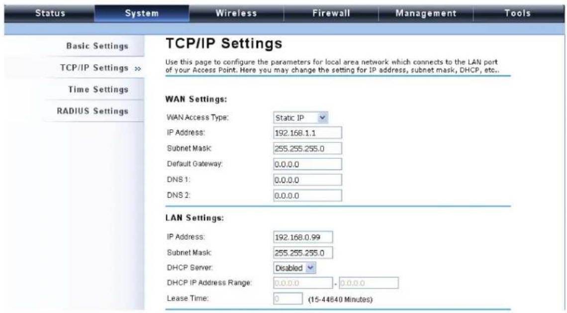
Figure 5-52. TCP/IP Settings screen, WAN and LAN Settings.
WAN Settings: Specify the Internet access method to Static IP, DHCP, or PPPOE. Users must enter WAN IP Address, Subnet Mask, and Gateway settings provided by your ISPs.
LAN Settings: When DHCP Server is disabled, users can specify IP address and subnet mask for the Wireless Ethernet Extender manually. Make sure the specified IP address is unique on your network in order to prevent IP conflict. When DHCP Server is enabled, users may specify DHCP IP Address Range, DHCP Subnet Mask, DHCP Gateway and Lease Time (15–44640 minutes). A DHCP relay agent is used to forward DHCP requests and replies between clients and servers when they are not on the same physical subnet. To enable the DHCP relay agent, check the "Enable DHCP Relay" checkbox and enter the IP address of the DHCP server.
WARNING:
In AP mode, the IEEE 802.11n VAC Access Point must establish connection with another wireless device before it is set to Router mode. To access the unit in Router mode via wired port, type the WAN IP address to enter the web page for WAN on the wired port and LAN the on wireless port. Or, you can access device through the wireless device connected with the Wireless Ethernet Extender.
In wireless client mode, users can access the Wireless Ethernet Extender via its wired port, for WAN is on wireless port and LAN is on wired port when device is set to Router mode.
Bridge mode and AP Repeater mode are similar to AP mode when device is set to Router mode; WAN is on wired port and LAN is on wireless port. Thus users must also connect the Wireless Ethernet Extender with another wireless device before it is set to Router mode and access the VAC Access Point via the connected wireless device.
Time Settings
Compliant with NTP, the Wireless Ethernet Extender can keep its time in accord with the Internet time. To use this feature, check Enable NTP Client Update in advance.

Figure 5-53. Time Settings screen.
Current Time
Display the present time in Yr, Mon, Day, Hr, Min, and Sec.
Time Zone Select
Select the time zone from the dropdown list.
NTP Server
Select the time server from the "NTP Server" dropdown list. Or manually input the IP address of the available time server into "Manual IP."
RADIUS Settings
RADIUS (Remote Authentication Dial-In User Service) is a server for remote user authentication and accounting; playing a central role in the network in providing the capabilities of authenticating, authorizing, accounting, auditing, alarming, etc. It allows an organization to maintain user profiles in a central database that all remote servers can share. If 802.1X, WPA(2) is used, you need to configure radius settings.
Open "RADIUS Settings" in "System" to make RADIUS configuration.

Figure 5-54. RADIUS Settings screen.
Authentication RADIUS Server
This is for RADIUS authentication. It can communicate with RADIUS through IP Address, Port, and Shared Secret.
IP Address: Enter the IP address of the Radius Server;
Port: Enter the port number of the Radius Server;
Shared Secret: This secret, which is composed of no more than 31 characters, is shared by the IEEE 802.11n VAC Access Point and RADIUS during authentication.
Global-Key Update
Check this option and specify the time interval between two global-key updates. Default is 3600 seconds.
Firewall Settings
The firewall is a system or group of systems that enforce an access control policy between two networks. It may also be defined as a mechanism used to protect a trusted network from an un-trusted network. The Wireless Ethernet Extender uses Source IP Filtering, Destination IP Filtering, Source Port Filtering, Destination Port Filtering, Port Forwarding, and DMZ. This is available only under Router Mode.
Source IP Filtering

Figure 5-55. Source IP Filtering screen.
You may create and activate a rule that filters a packet based on the source IP address from your local network to Internet. Check "Enable Source IP Filtering" to activate rule.
Local IP Address: Enter the IP address you would like to restrict.
Comment: Make comments to record your filtering rule.
Click Apply and the IP address will be added in the list. To delete the IP address from filtering, click Select checkbox of the designated IP address and click the Delete Selected button. You may delete all the IP addresses in the list by clicking Delete All.
Destination IP Filtering

Figure 5-56. Destination IP Filtering screen.
You may create and activate a rule that filters a packet based on the destination IP address to restrict the local computers from accessing certain websites. Check "Enable Destination IP Filtering" to activate a rule.
Destination IP Address: Enter the IP address to be restricted.
Comment: Make comments to record your filtering rule.
Click Apply and the IP address will be added in the list. To delete the IP address from filtering, click Select checkbox of the designated destination IP address and click the Delete Selected button. To delete all the IP addresses in the list, click Delete All.
Source Port Filtering

Figure 5-57. Source Port Filtering screen.
You may create and activate a rule that filters a packet based on the source port from your local network to Internet. Check "Enable Source Port Filtering" to activate a rule.
Port Range: Enter the port range you would like to restrict.
Protocol: Select port protocol: Both, TCP, UDP.
Comment: Make comments to record your filtering rule.
Click Apply and the IP address will be added in the list. To delete the restricted source ports, click Select checkbox of the designated ports and click the Delete Selected button. To delete all the IP addresses in the list, click Delete All.
Destination Port Filtering

Figure 5-58. Destination Port Filtering screen.
You may create and activate a rule that filters a packet based on the destination port from your local network to Internet. Check "Enable Destination Port Filtering" to activate rule.
Port Range: Enter the port range you would like to restrict.
Protocol: Select port protocol: Both, TCP, UDP.
Comment: Make comments to record your filtering rule.
Click Apply and the IP address will be added in the list. To delete the restricted destination ports, click Select checkbox of the designated ports and click the Delete Selected button. To delete all the IP addresses in the list, click Delete All.
Port Forwarding

Figure 5-59. Port Forwarding screen.
Port forwarding allows you to automatically redirect common network services to a specific machine behind the NAT firewall. These settings are only necessary if you wish to host some sort of server like a web server or mail server on the private local network behind the Wireless Ethernet Extender's NAT firewall. Check the Enable Port Forwarding checkbox to activate port forwarding.
IP Address: Enter the IP address the local server.
Protocol: Select Both, UDP, or TCP.
Port Range: Specify the port range.
Comment: Make comments to record the port forwarding rule.
UDP Pass Through
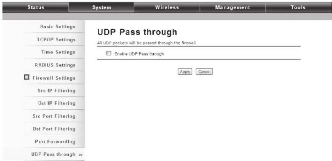
Figure 5-60. UDP Passthrough screen.
Check Enable UDP Pass through to allow all the UDPs packets to pass through the firewall.
NOTE: Opening all the UDP ports will be very likely to expose the network to intruders.
DMZ
A Demilitarized Zone is used to provide Internet services without sacrificing unauthorized access to its local private network. Typically, the DMZ host contains devices accessible to the Internet traffic, such as Web (HTTP) servers, FTP servers, SMTP (e-mail) servers and DNS servers. To activate DMZ, check the Enable DMZ checkbox.

Figure 5-61. DMZ screen.
DMZ Host IP Address: Enter the local host IP address.
5.3.3 Wireless
Open "Basic Settings" in "Wireless" as shown next to make basic wireless configuration.

Figure 5-62. Wireless Basic Settings screen.
Disable Wireless LAN Interface
Check this option to disable the WLAN interface, then the wireless module of Wireless Ethernet Extender will stop working and no wireless device can connect to it.
Operation Mode
Four operating modes are available in IEEE 802.11n VAC Access Point when it acts as a FAT AP.
AP: The Wireless Ethernet Extender establishes a wireless coverage and receives connectivity from other wireless devices.
Wireless Client: The Wireless Ethernet Extender is able to connect to the AP and thus join the wireless network around it.
Bridge: The Wireless Ethernet Extender establishes wireless connectivity with other APs by keying in remote MAC address. Please refer to the "WDS Settings" for detailed configuration.
AP Repeater: The Wireless Ethernet Extender serves as AP and Bridge concurrently. In other words, the IEEE 802.11n VAC Access Point can provide connectivity services for CPEs under Bridge mode.
Wireless Network Name (SSID)
This wireless network name is shared among all associated devices in your wireless network. Keep it identical on all those devices.
NOTE: The SSID is case-sensitive and can not exceed 32 characters.
Broadcast SSID
Under AP mode, hiding network name is necessary when you are in a wireless environment that may have potential risk. By | disabling broadcast SSID, the STA can not scan and find the Wireless Ethernet Extender, so that malicious attack by some illegal STA could be avoided.
802.11 Mode
The Wireless Ethernet Extender can communicate with 802.11b/g or 802.11b/g/n wireless devices.
HT Protect
Enable HT (High Throughput) protect to ensure HT transmission with MAC mechanism. Under 802.11n mode, a wireless client can be divided into HT STA and Non-HT STA, among which the one with HT protect enabled gets higher throughput.
Frequency/Channel
Channel varies much as the available band differs from country to country. Select a proper operating channel in the drop-down list according to your situation.
Extension Channel
Only applicable to AP, AP Repeater, and 40 MHz channel width, extension channel indicates the use of channel bonding that allows the Wireless Ethernet Extender to use two channels at once. Two options are available: Upper Channel and Lower Channel.
Channel Mode
Four levels are available: 5 MHz, 10 MHz, 20 MHz, and 40 MHz. The last one can enhance data throughput, but it takes more bandwidth, thus it might cause potential interference.
Antenna
By default, IEEE 802.11n VAC Access Point uses its built-in antenna for directional transmission; however, if you prefer to use an external antenna for your case-dependent applications, you can switch from "Internal (8 dBi)" to "External (N-Type)."
When External (N-Type) is selected, an Antenna Gain bar will appear to allow you specify the gain of the external antenna. The antenna gain calculates the TX power back off needed to remain in compliance with regulations.
NOTES:
You are able to choose "External (N-Type)" only when you have installed the external antenna properly; otherwise, the Wireless
Ethernet Extender might be damaged.
The maximum output power will vary depending on the country selected in order to comply with the local regulation.
The output power here is counted from the RF single chain only not including the 8dBi internal antenna.
Maximum Output Power (per chain)
Specify the signal transmission power. The higher the output power is, the wider the signal can cover, but the power consumption will be greater accordingly. The output power will vary depending on each country's regulation.
Data Rate
Usually "Auto" is preferred. Under this rate, the Wireless Ethernet Extender will automatically select the highest available rate to transmit. In some cases, however, where there is no great demand for speed, you can have a relatively-low transmit rate for compromise of a long distance.
Extension Channel Protection Mode
This is to avoid conflict with other wireless network and boost the ability of your device to catch all 802.11g transmissions. However, it may decrease wireless network performance. Compared to CTS-Self; the transmission amount of CTS-RTS is much lower.
Enable MAC Clone
Available only under wireless client mode, this hides the MAC address of the AP while it displays the one of associated wireless client or the MAC address is designated manually.
Site Survey
Under wireless client mode, the Wireless Ethernet Extender can perform site survey, detecting information on the available access points.
Open "Basic Settings" in "Wireless" by clicking the "Site Survey" button beside the "Wireless Mode" option. The wireless site survey window will pop up with a list of available AP in the vicinity. elect the AP you would like to connect and click "Selected" to establish connection.
| Select | SSID | Frequency/Channel | MAC Address | Wireless Mode | Signal Strength | Security |
| ○ | aeap17 | 2412MHz(1) | 00:24:01:df:67:8e | 802.11B/G | -78 | WPA |
| ○ | aeap18 | 2412MHz(1) | 00:21:91:f6:f7:55 | 802.11B/G | -77 | NONE |
| ○ | FRITZ!Box Fon WLAN 7270 | 2412MHz(1) | 00:24:fe:46:b9:c8 | 802.11B/G/N | -75 | WPA2 |
| ○ | RT-G32 | 2437MHz(6) | 20:cf:30:d6:5a:d0 | 802.11B/G | -62 | WEP |
| ○ | MIS-AP2 | 2437MHz(6) | 00:13:f7:8e:8d:d3 | 802.11B/G/N | -49 | WPA2 |
| ○ | HTC | 2437MHz(6) | 90:21:55:c2:3f:9c | 802.11B/G | -81 | NONE |
| ○ | DIR-635 | 2462MHz(11) | 00:24:a5:b4:cf:77 | 802.11B/G | -64 | WPA |
| ○ | Apple Network 873e69 | 2417MHz(2) | 10.9a:dd:87:3e:69 | 802.11B/G/N | -75 | WPA2 |
| ○ | ASIX_WIFI | 2422MHz(3) | 00:1e:58:29:28:27 | 802.11B/G | -65 | NONE |
Figure 5-63. Wireless Site Survey screen.
VAP Profile Settings
Available in AP mode, the Wireless Ethernet Extender allows up to 16 virtual SSIDs on a single BSSID and to configure different profile settings such as security and VLAN ID to each SSID. To create a virtual AP, you may check the Enable box of the profile and click on the profile (eg. Profile 2) to configure wireless and security settings. Click Apply to active the profile.
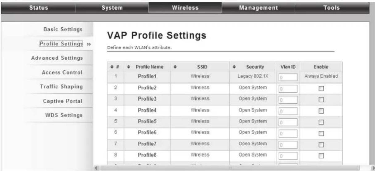
Figure 5-64. VAP Profile Settings screen.
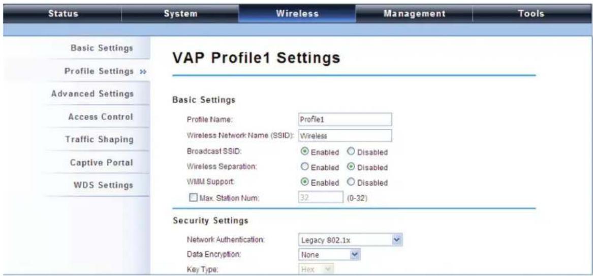
Figure 5-65. VAP Profile1 Settings screen.
Basic Setting
Profile Name: Name of the VAP profile.
Wireless Network Name: Enter the virtual SSID for the VAP.
Broadcast SSID: In AP mode, hiding network name is necessary when you are in a wireless environment that may have potential risk. By disabling broadcast SSID, the STA cannot scan and find the Wireless Ethernet Extender, so that malicious attack by some illegal STA can be avoided.
Wireless Separation: Wireless separation is an ideal way to enhance the security of network transmission. Under the mode except wireless client mode, enabling "Wireless Separation" can prevent the communication among associated wireless clients.
WMM Support: WMM (Wi-Fi Multimedia) is a subset of 802.11e. It allows wireless communication to define a priority limit on the basis of data type under AP mode only, thus those time-sensitive data, like video/audio data, may own a higher priority than a common one. To enable WMM, the wireless client should also support it
Max. Station Number: By checking the "Max. Station Num" the Wireless Ethernet Extender will only allow up to 32 wireless clients to associate with for better bandwidth for each client. By disabling the checkbox the Wireless Ethernet Extender will allow up to 128 clients to connect, but it is likely to cause network congestion or poor performance.
Security Setting
To prevent unauthorized radios from accessing data transmitting over the connectivity, the Wireless Ethernet Extender provides you with rock-solid security settings.
Network Authentication
Open System: This allows any device to join the network without performing any security check.
Shared Key: Data encryption and key are required for wireless authentication (Not available in Bridge/AP Repeater mode).
Legacy 802.1x: This provides the rights to access the wireless network and wired Ethernet. With User and PC identity, centralized authentication as well as dynamic key management, it controls the security risk of wireless network to the lowest. To serve the 802.1x, at least one EAP type should be supported by the RADIUS Server, AP, and wireless client.
WPA with RADIUS: Wi-Fi Protected Access (WPA) is a subset of the IEEE 802.11i standard. With warrant (username, password and etc.) offered by user, this kind of authentication can be realized with specific RADIUS server. This is the common way to be adopted in large enterprise network.
WPA2 with RADIUS: WPA2 (IEEE 802.11i) is a wireless security standard that defines stronger encryption, authentication and key management than WPA. If it is selected, AES encryption and RADIUS server are required.
WPA&WPA2 with RADIUS: It provides options of WPA (TKIP) or WPA2 (AES) for the client. If it is selected, the data encryption type must be TKIP + AES and the RADIUS server must be set.
NOTE: If Radius relevant authentication type is selected, please go to Wireless—>Radius Settings for further radius server configuration.
WPA-PSK: This is a simplified WPA mode with no need for specific authentication server. In this so-called WPA Pre-Shared Key, all you have to do is just pre-enter a key in each WLAN node and this is the common way to be adopted in large and middle enterprise as well as residential network.
WPA2-PSK: As a new version of WPA, only if all the clients support WPA2 can it be available. If it is selected, the data encryption can only be AES and the passphrase is required.
WPA-PSK&WPA2-PSK: Available in AP mode, this provides WPA (TKIP) or WPA2 (AES) encryption options for the client. If it is selected, the data encryption can only be TKIP + AES and the passphrase is required.
Data Encryption
If data encryption is enabled, the key is required and only by sharing the same key with other wireless devices can the communication be established.
None: Available only when the authentication type is open system.
64 bits WEP: This is made up of 10 hexadecimal numbers.
128 bits WEP: This is made up of 26 hexadecimal numbers.
152 bits WEP: This is made up of 32 hexadecimal numbers.
TKIP: Temporal Key Integrity Protocol, which is a kind of dynamic encryption, is used with WPA-PSK, etc.
AES: Advanced Encryption Standard, it is commonly used with WPA2-PSK, WPA, WPA2, etc.
TKIP + AES: It allows for backwards compatibility with devices using TKIP.
NOTES:
We strongly recommend you enable wireless security on your network!
Only with the same Authentication, Data Encryption and Key among the Wireless Ethernet Extender and wireless clients can the communication be established!
VLAN
If your network uses VLANs, you can assign one SSID to a VLAN, and client devices using the SSID are grouped in that VLAN.
To allow users on the VLAN to access the Wireless Ethernet Extender's Web page, you need to enable "Enable 802.1Q VLAN" and assign a management VLAN ID for your device. Make sure the assigned management VLAN ID is identical to your network VLAN ID to avoid failures in accessing the Wireless Ethernet Extender's Web page.

Figure 5-66. VLAN screen.
Advanced Settings
Open "Advanced Settings" in "Wireless" to make advanced wireless settings.

Figure 5-67. Wireless Advanced Settings screen.
A-MPDU/A-MSDU Aggregation
The data rate of your AP except wireless client mode could be enhanced greatly with this option enabled; however, if your wireless clients don't support A-MPDU/A-MSDU aggregation, we do not recommend to enabling it.
Short GI
Under 802.11n mode, enable it to obtain a better data rate if there is no negative compatibility issue.
RTS Threshold
The Wireless Ethernet Extender sends RTS (Request to Send) frames to certain receiving station and negotiates the sending of a data frame. After receiving an RTS, that STA responds with a CTS (Clear to Send) frame to acknowledge the right to start transmission. The setting range is 0 to 2346 bytes. Setting it too low may result in poor network performance. We recommend leaving it at its default of 2346.
Fragmentation Length
Specify the maximum byte size for a packet before data is fragmented into multiple packets. Setting it too low may result in poor network performance. We recommend leaving it at its default of 2346.
Beacon Interval
Specify the frequency interval to broadcast packets. Enter a value between 20 and 1024.
DTIM Interval
DTIM, which stands for Delivery Traffic Indication Message, is contained in the data packets. It is for enhancing the wireless transmission efficiency. The default is set to 1. Enter a value between 1 and 255.
Preamble Type
This defines some details on the 802.11 physical layer. "Long" and "Auto" are available.
IGMP Snooping
Available in AP/Router mode, IGMP snooping is the process of listening to IGMP network traffic. By enabling IGMP snooping, the AP will listen to IGMP membership reports, queries, and leave messages to identify the ports that are members of multicast groups. Multicast traffic will only be forwarded to ports identified as members of the specific multicast group or groups.
RIFS
RIFS (Reduced Interframe Spacing) reduces overhead, thereby increasing network efficiency.
Link Integration
Available under AP/Bridge/AP repeater mode, this monitors the connection on the Ethernet port by checking "Enabled." It can inform the associating wireless clients as soon as the disconnection occurs.
TDM Coordination
Stands for "Time-Division Multiplexing Technique," this resource reservation control mechanisms can avoid packet collisions and send the packets much more efficiently allowing for higher effective throughput rates. This function is only available in AP/CPE mode. We highly recommend enabling TDM coordination when there are multiple CPEs needed to connect to the AP in your application.
LAN2LAN CPE
LAN2LAN CPE mode enables packet forwarding at layer 2 level. It is fully transparent for all the Layer 2 protocols.
Space in Meter
To decrease the chances of data retransmission at long distance, the Wireless Ethernet Extender can automatically adjust proper ACK timeout value by specifying distance of the two nodes.
Flow Control
This allows the administrator to specify the incoming and outgoing traffic limit by checking "Enable Traffic Shaping." This is only available in Router mode.
NOTE: We strongly recommend you leave most advanced settings at their defaults except "Distance in Meters." Adjust this parameter for real distance; any modification may negatively impact the performance of your wireless network.
Access Control
The Access Control appoints the authority to wireless client on accessing IEEE 802.11n VAC Access Point, thus a further security mechanism is provided. This function is available only under AP/Router mode.
Open "Access Control" in "Wireless Settings" as shown next.

Figure 5-68. Wireless Access Control screen.
Profile Selection
Select the VAP network you would like to enable access control.
Access Control Mode
If you select "Allow Listed," only those clients whose wireless MAC addresses are in the access control list will be able to connect to your AP. When "Deny Listed" is selected, those wireless clients on the list will not be able to connect the AP.
MAC Address
Enter the MAC address of the wireless client that you would like to list in the access control list, then click "Apply" and it will be added to the table at the bottom.
Delete Selected/All
Check the box before one or more MAC addresses of wireless client(s) that you would like to cancel, and click "Delete Selected" or "Delete All" to cancel that access control rule.
Traffic Shaping
This allows the administrator to manage the traffic flow to ensure optimal performance.
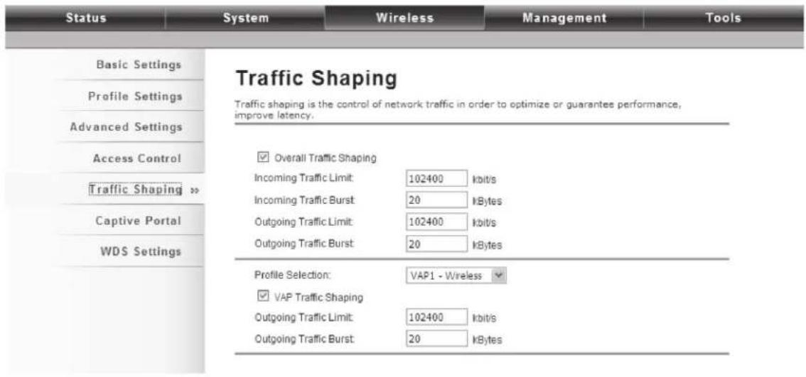
Figure 5-69. Traffic Shaping screen.
Overall Traffic Shaping
Check this box to control the overall bandwidth of the Wireless Ethernet Extender.
Incoming Traffic Limit: To specify the maximum incoming bandwidth to a certain rate in kbps.
Incoming Traffic Burst: To specify the buffer size for incoming traffic that can be sent within a given unit of time. The suggested value is 20 KBytes. You may just leave the default value there, and then the connection will be bound to the traffic shaping rule at all times. You may decrease it to smaller value if the incoming traffic limit is smaller.
Outgoing Traffic Limit: To limit the outbound traffic to a certain rate in kbit/s.
Outgoing Traffic Burst: To specify the buffer size for outbound traffic. The suggested value is 20KBytes. You may decrease it to smaller value if the outbound traffic limit is smaller.
VAP Traffic Shaping
Check this box to control the overall bandwidth for a specific VAP network.
Incoming Traffic Limit: To specify maximum incoming bandwidth to a certain rate in kbps.
Incoming Traffic Burst: To specify the buffer size for incoming traffic that can be sent within a given unit of time. The suggested value is 20 KBytes. You may just leave the default value there, and then the connection will be bound to the traffic shaping rule at all times. You may decrease it to smaller value if the incoming traffic limit is smaller.
Captive Portal
Captive portal is management that allows WLAN users to easily and securely access the Internet. Under Router mode, when captive portal is enabled, the Wireless Ethernet Extender will redirect the client to go to an authentication web page before browsing Internet web pages. Captive portals are used on most Wi-Fi hotspots networks. Therefore, to use captive portal, you need to find the service providers that have the additional services needed to make captive portal work.

Figure 5-70. Captive Portal screen.
To enable Captive Portal, check "Captive Portal" and select the VAP network needed for captive portal.
Radius Settings
Primary Radius Server: Enter the name or IP address of the primary radius server.
Secondary Radius Server: Enter the name or IP address of the secondary radius server if any.
Radius Auth Port: Enter the port number for authentication.
Radius Acct Port: Enter the port number for billing.
Radius Shared Secret: Enter the secret key of the radius server.
Radius NAS ID: Enter the name of the radius server if any.
Radius Administrative-User
Radius Admin Username: Enter the username of the Radius Administrator.
Radius Admin Password: Enter the password of the Radius Administrator.
Captive Portal
UAM Portal URL: Enter the address of the UAM portal server.
UAM Secret: Enter the secret password between the redirect URL and the Hotspot.
WDS Settings
Extend the range of your network without having to use cables to link the Access Points by using the Wireless Distribution System (WDS): Simply put, you can link the Access Points wirelessly. Open "WDS Settings" in "Wireless" as shown next:

Figure 5-71. Wireless Broadband Access Point screen.
Enter the MAC address of another AP you wirelessly want to connect to into the appropriate field and click "Apply" to save the settings.
NOTES:
WDS Settings is available only under Bridge and AP Repeater Mode.
Bridge uses the WDS protocol that is not defined as the standard, so compatibility issues between equipment from different vendors may arise. Moreover, Tree or Star shape network topology should be used in all WDS use-cases (i.e. if AP2 and AP3 are specified as the WDS peers of AP1, AP2 should not be specified as the WDS peer of AP3 and AP3 should not be specified as the WDS peer of AP2 in any case). Mesh and Ring network topologies are not supported by WDS and should be avoided in all the use cases.
5.3.4 Management
Password
From the "Password Settings" screen in "Management," you can change the password to manage your Wireless Ethernet Extender.

Figure 5-72. Password Settings screen.
Current Password
Enter the current password.
New Password
Enter the new password.
Confirm Password
Enter the new password again for confirmation.
NOTE: The password is case-sensitive and its length cannot exceed 19 characters!
Upgrade Firmware
Open “Firmware Upload” in “Management” and follow the steps below to upgrade firmware locally or remotely through the Wireless Ethernet Extender’s Web:

Figure 5-73. Firmware Upgrade screen.
Click "Browse" to select the firmware file you would like to load;
Click "Upload" to start the upload process;
Wait a few minutes, the VAC Access Point will reboot after successful upgrade.
CAUTION: Do NOT cut the power off during upgrade, otherwise the system may crash!
Backup/Retrieve Settings
We strongly recommend you back up configuration information in case of something unexpected. If tragedy hits your device, you may have an access to restore the important files by the backup. All these can be done by the local or remote computer.
Open "Configuration File" in "Management" as shown next:
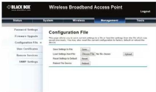
Figure 5-74. Configuration File screen.
Save Setting to File
Click "Save," and a dialog box will pop up. Save it, then the configuration file ap.cfg will be generated and saved to your local computer.
Load Settings from File
Click "Browse," and a file selection menu will appear. Select the file you want to load, like ap.cfg; Click "Upload" to load the file. After automatically rebooting, new settings are applied.
Restore Factory Default Settings
The IEEE 802.11n VAC Access Point provides two ways to restore the factory default settings:
Restore factory default settings via Web
From the "Configuration File" screen, clicking "Reset" will eliminate all current settings and reboot your device, then will apply default settings.

Figure 5-75. Configuration File screen, Reset settings to default.
Restore factory default settings via Reset Button
If software in the Wireless Ethernet Extender unexpectedly crashes, you can no longer reset the unit via Web. You may do hardware reset via the reset button. Press and hold the button for at least 5 seconds and then release it until the PWR LED blinks.
Reboot
You can reboot your Wireless Ethernet Extender from the "Configuration File" screen in "Management" as shown next: Click "Reboot" and click "Yes" when the prompt appears to start reboot process. This takes a few minutes.

Figure 5-76. Configuration File screen, Reboot the device option.
Remote Management
The Wireless Ethernet Extender provides a variety of remote management, including Telnet, SNMP, FTP, SSH, HTTPS and exclusive WISE tool, making configuration more convenient and secure.
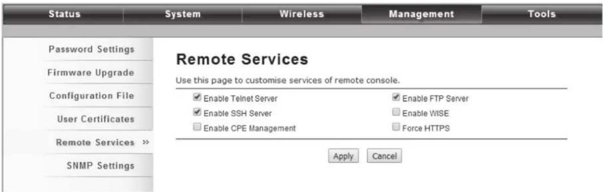
Figure 5-77. Remote Services screen.
SNMP Management
The Wireless Ethernet Extender supports SNMP for convenient remote management. Open the "SNMP Settings" screen in "Management" shown next. Set the SNMP parameters and obtain MIB file before remote management.
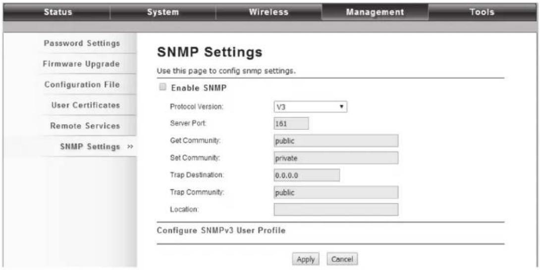
Figure 5-78. SNMP Settings screen.
Protocol Version: Select the SNMP version, and keep it identical on the IEEE 802.11n VAC Access Point and the SNMP manager. The Wireless Ethernet Extender supports SNMP v2/v3.
Server Port: Change the server port for a service if needed; however, you have to use the same port to use that service for remote management.
Get Community: Specify the password for the incoming Get and GetNext requests from the management station. By default, it is set to public and allows all requests.
Set Community: Specify the password for the incoming Set requests from the management station. By default, it is set to private.
Trap Destination: Specify the IP address of the station to send the SNMP traps to.
Trap Community: Specify the password sent with each trap to the manager. By default, it is set to public and allows all requests.
Configure SNMPv3 User Profile
For SNMP protocol version 3, you can click "Configure SNMPv3 User Profile" in blue to set the details of SNMPv3 user. Check "Enable SNMPv3 Admin/User" in advance and make further configuration.
User Name: Specify a user name for the SNMPv3 administrator or user. Only the SNMP commands carrying this user name are allowed to access the Wireless Ethernet Extender.
Password: Specify a password for the SNMPv3 administrator or user. Only the SNMP commands carrying this password are allowed to access the Wireless Ethernet Extender.
Confirm Password: Input that password again to make sure it is your desired one.
Access Type: Select "Read Only" or "Read and Write" accordingly.
Authentication Protocol: Select an authentication algorithm. SHA authentication is stronger than MD5 but is slower.
Privacy Protocol: Specify the encryption method for SNMP communication. None and DES are available. None means no encryption is applied. DES is a Data Encryption Standard that applies a 58-bit key to each 64-bit block of data.
Certificate Settings
Under Wireless Client mode, when EAP-TLS is used, the RADIUS server must know which user certificates to trust. The Server can trust all certificates issued by a given CA.
To import a user certificate, from Import User Certificates, click "Browse" and specify the location where the user certificate is placed. Click "Import."

Figure 5-79. User Certificates screen.
Delete User Certificate
Delete the selected user certificate.
Import User Certificates
Import the user certificate.
5.3.5 Tools
System Log
System log is used for recording events occurred on the Wireless Ethernet Extender, including station connection, disconnection, system reboot and etc.
Open "System Log" in "Tools" as shown next.

Figure 5-80. System Log screen.
Remote Syslog Server
Enable Remote Syslog: Enable System log to alert remote server.
IP Address: Specify the IP address of the remote server.
Port: Specify the port number of the remote server.
Ping Watch Dog
If you mess your connection up and cut off your ability the log in to the unit, the ping watchdog has a chance to reboot due to loss of connectivity.

Figure 5-81. Ping Watchdog screen.
Ping Watchdog
Enable Ping Watchdog: To activate ping watchdog, check this checkbox.
IP Address to Ping: Specify the IP address of the remote unit to ping.
Ping Interval: Specify the interval time to ping the remote unit.
Startup Delay: Specify the startup delay time to prevent reboot before the Wireless Ethernet Extender is fully initialized.
Failure Count To Reboot: If the ping timeout packets reached the value, the Wireless Ethernet Extender will reboot automatically.
Site Survey
Only available under Wireless Client mode, site survey allows you to scan all the APs within coverage.
Open "Site Survey" in "Tools" as below and select the desired AP to connect.

Figure 5-82. Site Survey screen.
Date Rate Test
The Data Rate Test allows you test the current RSSI at each data rate between your IEEE 802.11b/g/n Wireless CPEs.
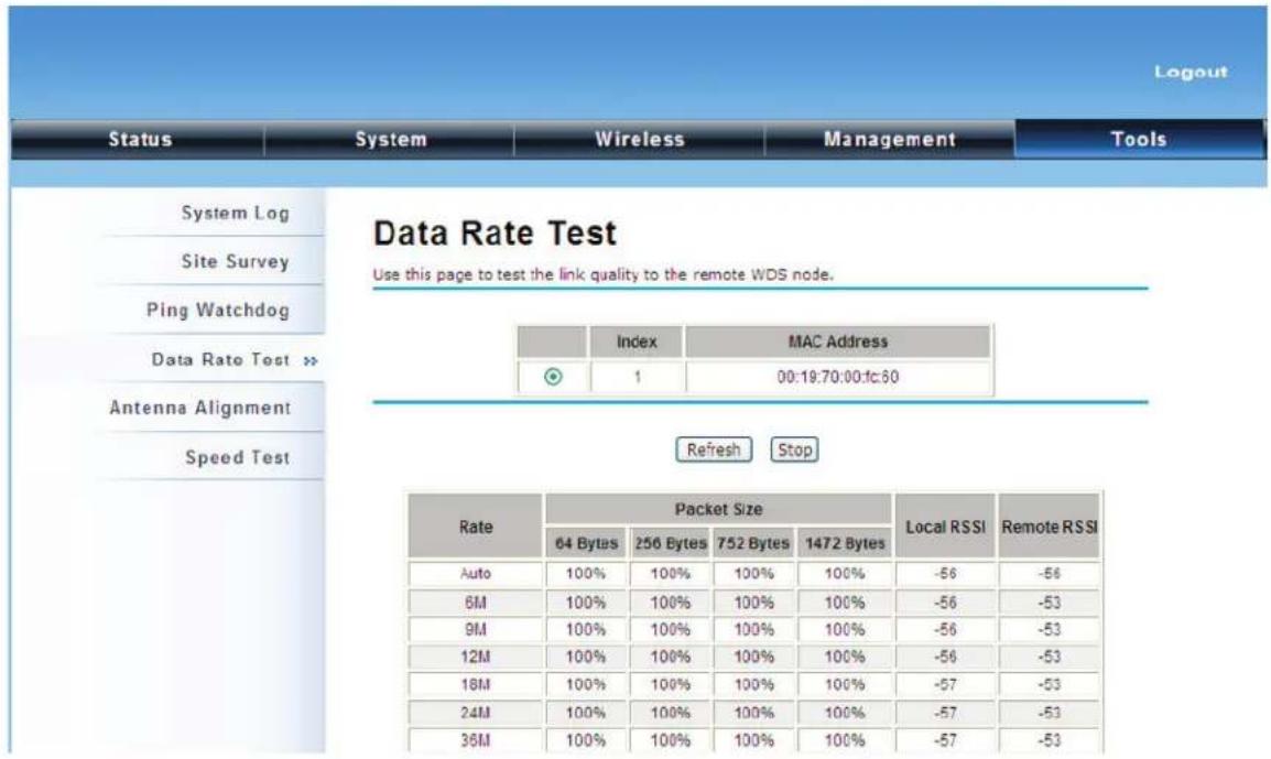
Figure 5-83. Data Rate Test screen.
Antenna Alignment
Under Bridge mode, when the bridges are not easily visible from the location where the dish will be installed, the antenna alignment tool can help you evaluate the position of the unit and adjust the angle of the antenna more precisely. In real circumstances a lot of additional factors should be taken into account when your unit is installed. These factors include various obstacles (buildings, trees), the landscape, the altitude, transponder orientation, polarization, etc.
To use the tool, select the desired remote WDS bridge and click "Start", and the web page will display the measured signal strength, RSSI, and transmit/receive packets. If the signal quality is not quite good, try to adjust the antenna and see if the quality improves or not.

Figure 5-84. Antenna Alignment screen.
Speed Test
The speed test monitors the current data transmission (TX) and data reception (RX) rate with the remote 802.11an Wireless Outdoor CPE. Enter the IP address of the remote CPE, type in the user name/password and click "Test". The result will display in the bottom STATUS. You may test single TX/RX or bi-direction.
Appendix. ASCII
WEP can be configured with a 64-bit, 128-bit or 152-bit Shared Key (hexadecimal number or ACSII). As defined, a hexadecimal number is represented by 0–9, A–F or a–f; ACSII is represented by 0–9, A–F, a–f, or punctuation. Each one consists of a two-digit hexadecimal value.
| Table A-1. ASCII and Hex Equivalents. | |||||||
| ASCII Character | Hex Equivalent | ASCII Character | Hex Equivalent | ASCII Character | Hex Equivalent | ASCII Character | Hex Equivalent |
| ! 21 9 39 Q 51 i 69 | |||||||
| " 22 : 3A R 52 j 6A | |||||||
| # | 23 | ; | 3B | S | 53 | k | 6B |
| $ 24 < | 3C T 54 | 6C | |||||
| % | 25 | = | 3D | U | 55 | m | 6D |
| & | 26 | > | 3E | V | 56 | n | 6E |
| ' | 27 ? | 3F W 57 | o 6F | ||||
| ( | 28 | @ | 40 | X | 58 | p | 70 |
| ) | 29 A | 41 Y | 59 q 71 | ||||
| * 2A | B 42 Z 5A r | 72 | |||||
| , | 2B | C | 43 | [ | 5B | s | 73 |
| - | 2C | D | 44 | \ | 5C | t | 74 |
| . | 2D | E | 45 | ] | 5D | u | 75 |
| / | 2E | F | 46 | ^ | 5E | v | 76 |
| 0 | 2F | G | 47 | _ | 5F | w | 77 |
| 1 | 30 | H | 48 | ' | 60 | x | 78 |
| 1 | 31 | I | 49 | a | 61 | y | 79 |
| 2 | 32 | J | 4A | b | 62 | z | 7A |
| 3 | 33 | K | 4B | c | 63 | { | 7B |
| 4 | 34 | L | 4C | d | 64 | | | 7C |
| 5 | 35 | M | 4D | e | 65 | } | 7D |
| 6 | 36 | N | 4E | f | 66 | ~ | 7E |
| 7 | 37 | O | 4F | g | 67 | ||
| 8 | 38 | P | 50 | h | 68 | ||
Black Box Tech Support: FREE! Live. 24/7.
Tech support the way it should be.

natural_image
Close-up portrait of a smiling man with short hair and beard, holding a small object near his ear (no text or symbols visible)Great tech support is just 60 seconds away at 724-746-5500 or blackbox.com.

BLACK BOX®
About Black Box
Black Box provides an extensive range of networking and infrastructure products. You'll find everything from cabinets and racks and power and surge protection products to media converters and Ethernet switches all supported by free, live 24/7 Tech support available in 60 seconds or less.
© Copyright 2016. Black Box Corporation. All rights reserved. Black Box ® and the Double Diamond logo are registered trademarks of BB Technologies, Inc. Any third-party trademarks appearing in this manual are acknowledged to be the property of their respective owners.


- Wireless Ethernet Extender
- User Manual
- Trademarks Used in this Manual
- Disclaimer:
- Federal Communications Commission and Industry Canada Radio Frequency Interference Statements
- FCC Radiation Exposure Statement
- Overview
- Introduction
- Features
- What's Included
- Hardware Description
- Typical Management Scenario
- Installation
- Preparing for Installation
- Safety Precautions
- Installation Precautions
- System Installation
- Connect up
- Connect up
- Using the Grounding Wire
- Install the External Antenna
- Mount the AP on a Pole
- Power Up
- Connect to the Extender
- Quick Setup Tutorial
- Access the Web Configurator
- Configure the AC+Thin AP mode
- Firmware Upgrade for Ethernet Extender in AC mode
- Install the Managed Thin AP
- Selected #Device Name # MAC IP #FW # Status #Clients TX #RX
- Manage the extender-managed APs
- Firmware Upgrade for the Ethernet Extender in AC mode
- Monitor the Ethernet Extender-Managed AP
- Configure the Fat AP mode
- AP Mode
- Wireless Client Mode
- Wireless Site Survey
- Bridge Mode
- AP Repeater Mode
- Navigate the Web Configurator
- Virtual AC+Thin AP Mode
- Status
- View Managed APs
- View Wireless Users
- View DHCP Client Table
- Wireless Settings
- Wireless Networks (VAP Profiles Settings)
- Basic Setting
- Security Setting
- Network Authentication
- Data Encryption
- Network Basic Setting
- Wireless Protocols
- Basic Settings
- Advanced Settings
- Access Control
- Access Control Mode
- MAC Address
- Delete Selected/All
- Traffic Shaping
- Enable Traffic Shaping
- Interface Selection
- Outgoing Traffic Rate
- Outgoing Traffic Burst
- Radius Settings
- Authentication RADIUS Server
- Global-Key Update
- TCP/IP Settings
- LAN Settings
- Captive Portal
- Radius Administrative-User
- Firewall Settings
- Source IP Filtering
- Destination Port Filtering
- Port Forwarding
- Management
- AP Management
- System Settings
- Device Settings
- IP Address Assignment
- DHCP Server
- Time Settings
- Current Time
- Time Zone Select
- NTP Server
- Firmware Upgrade
- Upload AC Firmware
- Upload TAP Firmware
- Backup/ Retrieve Settings
- Save AC Settings to File
- Save TAP Settings to File
- Load Settings from File
- Restore Factory Default Settings
- Restore factory default settings via Web
- Restore factory default settings via Reset Button
- Reboot
- Password Settings
- Current Password
- New Password
- Confirm Password
- Syslog Settings
- Remote Syslog Server
- Send Syslog via Email
- Mail Server Setting
- System Log
- System Alert
- Time Source Message
- Tools
- Destination IP Address
- Thin AP Mode
- Information
- Basic Settings
- General Settings
- Enable 802.1Q VLAN
- FAT AP Mode
- Status
- View Association List
- Association Node Details
- View Network Flow Statistics
- Poll Interval
- View ARP Table
- View Bridge Table
- View Active DHCP Client Table
- View Network Activities
- System
- GPS Coordinate Settings
- NOTES:
- WARNING:
- Destination IP Filtering
- Source Port Filtering
- UDP Pass Through
- DMZ
- Wireless
- Disable Wireless LAN Interface
- Operation Mode
- Wireless Network Name (SSID)
- Broadcast SSID
- Mode
- HT Protect
- Frequency/Channel
- Extension Channel
- Channel Mode
- Antenna
- Maximum Output Power (per chain)
- Data Rate
- Extension Channel Protection Mode
- Enable MAC Clone
- Site Survey
- VAP Profile Settings
- Profile Name SSID Security Vlan ID Enable
- VLAN
- A-MPDU/A-MSDU Aggregation
- Short GI
- RTS Threshold
- Fragmentation Length
- Beacon Interval
- DTIM Interval
- Preamble Type
- IGMP Snooping
- RIFS
- Link Integration
- TDM Coordination
- LAN2LAN CPE
- Space in Meter
- Flow Control
- Profile Selection
- Overall Traffic Shaping
- VAP Traffic Shaping
- WDS Settings
- Management
- Password
- Upgrade Firmware
- Backup/Retrieve Settings
- Save Setting to File
- Remote Management
- SNMP Management
- Configure SNMPv3 User Profile
- Certificate Settings
- Tools
- Time Priority Source Message
- Ping Watch Dog
- Ping Watchdog
- Date Rate Test
- Antenna Alignment
- Speed Test
- Appendix. ASCII
- Black Box Tech Support: FREE! Live. 24/7.
- BLACK BOX®
- About Black Box
Brand : Black Box
Model : LWE121A
Category : Wi-Fi repeater