
LB510A-R2 - Wi-Fi repeater Black Box - Free user manual and instructions
Find the device manual for free LB510A-R2 Black Box in PDF.


| Product Type | Wi-Fi Repeater |
| Dimensions | 120 x 70 x 30 mm |
| Weight | 200 g |
| Power Supply | 5V DC, 1A via micro USB |
| Wireless Standard | IEEE 802.11 b/g/n (2.4 GHz) |
| Maximum Speed | 300 Mbps |
| Range | Up to 300 feet (90 meters) indoors |
| Main Functions | Extends Wi-Fi range, WPS button, Ethernet port, AP mode |
| Care and Cleaning | Wipe with a dry, soft cloth. Do not use liquids. |
| Safety | Keep away from water and heat sources. Use only the supplied power adapter. |
| Spare Parts and Repairability | Not user-serviceable. Contact Black Box support for repairs. |
| General Information | Brand: Black Box, Model: LB510A-R2, Color: Black |
Frequently Asked Questions - LB510A-R2 Black Box
User questions about LB510A-R2 Black Box
0 question about this device. Answer the ones you know or ask your own.
Ask a new question about this device
Download the instructions for your Wi-Fi repeater in PDF format for free! Find your manual LB510A-R2 - Black Box and take your electronic device back in hand. On this page are published all the documents necessary for the use of your device. LB510A-R2 by Black Box.
USER MANUAL LB510A-R2 Black Box
10BASE-T/100BASE-TX G.SHDSL Two-Wire Extender/NTU
Extend corporate LAN-to-WAN communications at higher speeds or at a longer distance.
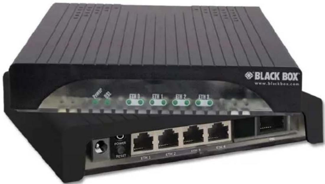
TABLE OF CONTENTS
1. GENERAL INFORMATION 9
1.1 Features ......9
1.2 Description....9
1.3 Power Input Connector.... 10
1.3.1 External AC universal power supply 10
1.3.2 External 48 VDC power supply.... 11
2. CONFIGURATION.... 11
2.1 Software (CLI) Configuration 11
2.2 Hardware (dip-switch) Configuration 12
2.3 Configuring the Dip Switches.... 13
2.4 System Reset Mode 14
2.5 DIP Switch Settings 14
2.5.1 Switches S4-2 through S4-8 define the DSL line rate.....15
2.6 Ethernet Management Port.... 18
2.6.1 Help commands....19
2.6.2 System configuration commands.... 20
2.6.3 System status commands.... 20
2.6.4 DSL configuration commands.... 20
2.6.5 DSL status command.... 21
2.6.6 DSL clear Errcntrs command.... 21
2.7 Remote Console.... 21
2.7.1 Example Command Line Interface Session....21
3. INSTALLATION 23
3.1 Connecting the DSL Interface 23
3.2 Connecting the Ethernet Interface.... 24
3.3 Connecting Power 24
3.3.1 External AC universal power supply 24
3.3.2 DC Power 25
4. OPERATION.... 25
4.1 Power-up 25
4.2 LED Status Monitors.... 25
4.2.1 Power (Green) 26
4.2.2 DSL (Green).... 26
4.2.3 Link (Green).... 26
4.2.4 Activity (Green) 26
4.3 Test Modes.... 27
4.3.1 Loopbacks ......27
4.3.2 Patterns.... 28
5. REMOTE CONSOLE OPERATION.... 28
5.1 Establishing a Remote Console Session 29
5.1.1 How to Connect .....29
5.1.2 How to Disconnect.... 31
5.1.3 Differences in local and remote control session behavior .....31
-
SOFTWARE UPGRADE 32
-
RESET CONFIGURATION TO FACTORY DEFAULTS 33
A. SPECIFICATIONS 34
A.1 Clocking Modes 34
A.2 DTE Rate 34
A.3 Ethernet Interface 34
A.4 Diagnostics ....34
A.5 Status LED 34
A.5.1 Power (Green)....34
A.5.2 DSL (Green)....34
A.5.3 Link (Green)....34
A.5.4 Activity (Green) 34
A.6 Configuration 35
A.7 Power and Power Supply Specifications ....35
A.7.1 External AC universal power supply ....35
A.7.2 External 48 VDC power supply....36
A.8 Transmission Line 36
A.9 Line Coding 36
A.10 Line Rates DSL Line 36
A.11 Line Interface 36
A.12 G.SHDSL Physical Connection 36
A.13 Temperature Range 37
A.14 Humidity 37
A.15 Altitudde 37
A.16 Dimensions 37
A.17 Third Party Software Licenses ....37
B. FACTORY DEFAULT VALUES.... 38
B.1 Factory Default Values for Software-Configuration Parameters .....38
C. INTERFACE PINOUTS 39
C.1 Line Port 39
C.1.1 RJ-45....39
C.2 ETHERNET PORT 39
C.2.1 RJ-45 socket 10/100Base-T....39
RADIO FREQUENCY INTERFERENCE STATEMENTS
FEDERAL COMMUNICATIONS COMMISSION AND INDUSTRY CANADA RADIO FREQUENCY INTERFERENCE STATEMENTS
This equipment generates, uses, and can radiate radio-frequency energy, and if not installed and used properly, that is, in strict accordance with the manufacturer's instructions, may cause interference to radio communication. It has been tested and found to comply with the limits for a Class A computing device in accordance with the specifications in Subpart B of Part 15 of FCC rules, which are designed to provide reasonable protection against such interference when the equipment is operated in a commercial environment. Operation of this equipment in a residential area is likely to cause interference, in which case the user at his own expense will be required to take whatever measures may be necessary to correct the interference.
Changes or modifications not expressly approved by the party responsible for compliance could void the user's authority to operate the equipment.
This digital apparatus does not exceed the Class A limits for radio noise emission from digital apparatus set out in the Radio Interference Regulation of Industry Canada.
SAFETY WHEN WORKING WITH ELECTRICITY

WARNING
- This device contains no user serviceable parts. This device can only be repaired by qualified service personnel.
- Do not open the device when the power cord is connected. For systems without a power switch and without an external power adapter, line voltages are present within the device when the power cord is connected.
- For devices with an external power adapter, the power adapter shall be a listed Limited Power Source. The mains outlet that is utilized to power the device shall be within 10 feet (3 meters) of the device, shall be easily accessible, and protected by a circuit breaker in compliance with local regulatory requirements.
- For AC powered devices, ensure that the power cable used meets all applicable standards for the country in which it is to be installed.
- For AC powered devices which have 3 conductor power plugs (L1, L2 & GND or Hot, Neutral & Safety/Protective Ground), the wall outlet (or socket) must have an earth ground.
- For DC powered devices, ensure that the interconnecting cables are rated for proper voltage, current, anticipated temperature, flammability, and mechanical serviceability.
- WAN, LAN & PSTN ports (connections) may have hazardous voltages present regardless of whether the device is powered ON or OFF. PSTN relates to interfaces such as telephone lines, FXS, FXO, DSL, xDSL, T1, E1, ISDN, Voice, etc. These are known as “hazardous network voltages” and to avoid electric shock use caution when working near these ports. When disconnecting cables for these ports, detach the far end connection first.
- Do not work on the device or connect or disconnect cables during periods of lightning activity.

In accordance with the requirements of council directive 2002/96/EC on Waste of Electrical and Electronic Equipment (WEEE), ensure that at end-of-life you separate this product from other waste and scrap and deliver to the WEEE collection system in your country for recycling.
This device contains no user serviceable parts. This device can only be repaired by qualified service personnel.

This device is NOT intended nor approved for connection to the PSTN. It is intended only for connection to customer premise equipment.

Electrostatic Discharge (ESD) can damage equipment and impair electrical circuitry. It occurs when electronic printed circuit cards are improperly handled and can result in complete or intermittent failures. Do the following to prevent ESD:
• Always follow ESD prevention procedures when removing and replacing cards.
- Wear an ESD-preventive wrist strap, ensuring that it makes good skin contact. Connect the clip to an unpainted surface of the chassis frame to safely channel unwanted ESD voltages to ground.
- To properly guard against ESD damage and shocks, the wrist strap and cord must operate effectively. If no wrist strap is available, ground yourself by touching the metal part of the chassis.
1. GENERAL INFORMATION
Thank you for your purchase of this Black Box product. This product has been thoroughly inspected and tested and is warranted for one year for parts and labor. If any questions or problems arise during installation or use of this product, contact Black Box Technical Support at 724-746-5500 or info@blackbox.com.
1.1 FEATURES
- Symmetrical high data-rate DSL (G.SHDSL)
• Data rates up to 5.69 Mbps
• 10/100 Ethernet port for management and configuration - Plug ‘n’ Play for easy installations
- Interoperable with other Black Box G.SHDSL modems
- Configurable as remote (CP) units
- Configurable as central (CO) units to operate back-to-back
- Front-panel status indicators
- CE marked
1.2 DESCRIPTION
The Black Box LB510A-R2 G.SHDSL provides high-speed 2-wire 2-wire connectivity to ISPs, PTTs, and enterprise environments using Symmetrical High-data-rate Digital Subscriber Line (G.SHDSL) technology.
As a symmetric DSL CPE, DSL offers the same data rates in both directions over a single pair of regular twisted pair lines using TC-PAM modulation. Line connection is made with an RJ-45 jack. Standard versions of LB510A-R2 are powered by an 100/230 VAC (Universal) supply. The CPE features externally-accessible DIP switches, loopback diagnostics and remote-management capabilities via in-band management.
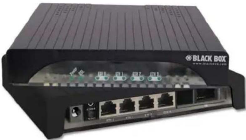
Figure 1. LB510A-R2
1.3 POWER INPUT CONNECTOR
The LB510A-R2 comes with an AC or DC power supply. (See Appendix A.7 on page 36.)
The power connection to the CPE is a 2.5 mm barrel receptacle with the center conductor positive (see figure 2).
- Rated voltage: 5 VDC
Rated current: 1 A

Figure 2. Power connection barrel receptacle 5 VDC diagram
1.3.1 External AC universal power supply
• Output from power supply: 5 VDC, 2 A
- Input to power supply: universal input 100-240 VAC 50/60 Hz 0.3A

The external AC adaptor shall be a listed limited power source that incorporates a disconnect device and shall be positioned within easy reach of the operator. Ensure that the AC power cable meets all applicable standards for the country in which it is to be installed, and that it is connected to a wall outlet which has earth ground.
1.3.2 External 48 VDC power supply
CAUTION
The external DC adaptor shall be a listed limited power source that incorporates a disconnect device and shall be positioned within easy reach of the operator. The interconnecting cables shall be rated for the proper voltage, current, anticipated temperature, flammability, and mechanical serviceability.
Input:
- Rated voltage: 36–60 VDC
• Rated current: 0.25 A DC
• 3-pin locking connector, 3.5 mm pitch
• Transient over-voltage protection, 100VDC at 2 ms
Output:
• Rated voltage: 5 VDC ± 5%, 5W
- Rated current; 1 A DC
- 6-inch cable terminated with 2.5 mm barrel plug, center positive
2. CONFIGURATION
You can configure the LB510A-R2 using the software configuration via the command line interface (CLI), or through the hardware configuration via DIP switches.
2.1 SOFTWARE (CLI) CONFIGURATION
To use the software configuration, you must set the S4 (Rate) DIP switches to the OFF position before powering up the LB510A-R2. When it is set for software-configuration mode, the device will read any configuration data previously saved to FLASH memory during system power-up. If no configuration data was previously saved to FLASH, then the LB510A-R2 will load the factory-default configuration from FLASH memory. After power-up, you may use console commands or the Embedded Operations Channel (EOC) to modify the configuration parameters.
2.2 HARDWARE (DIP-SWITCH) CONFIGURATION
To use DIP-switch configuration you must first set the DIP switches to a position other than all OFF or all ON before powering-up the LB510A-R2. When all the DIP switches are set to any position other than all OFF or all ON, the LB510A-R2 will operate in
hardware (DIP-switch)-configuration mode. In DIP-switch-configuration mode the device will read the DIP-switch settings during system startup and configure itself according to the switch settings. Once you power-up the LB510A-R2 in DIP-switch mode, it will operate in DIP-switch mode until powered down. When operating in DIP-switch mode you cannot change any configuration settings:
- Changing the DIP switch settings while the device is running requires the ds start command.
- If you attempt to modify the configuration by issuing console commands, the device will not execute your commands- except for the dsl start command and the show commands. Instead, the LB510A-R2 will respond with a message indicating the device is operating in DIP-switch-configuration mode.
- If you attempt to modify any configuration parameters via the EOC (by changing (EOC variables), the LB510A-R2 will not execute your changes.
The table below lists the LB510A-R2's configurable parameter.
Table 1: LB510A-R2 configurable parameters
| Parameter Description Possible Values | ||
| Password | The password used to login to the console.* | 1-10 characters |
| Circuit ID | The circuit ID used to identify the unit.* | 1-64 characters |
| DSL Data Rate/ Timeslots | Defines the number of DSL timeslots. The DSL data rate is calculated by the equation: data rate = DSL timeslots x 64k. | 1-72 timeslots |
| Annex The G.991.2 Annex A or B | ||
| Ethernet Man-agement | The LB510A-R2 provides various man-agement functions through the Ether-net interface. | OFF, Any port, or ETH 0 only |
| Loopback | The LB510A-R2 provides both a local loopback (LAL) and a remote loopback (RDL). This can be used to trouble-shoot problems. | OFF, LAL, or RDL |
| Pattern | The LB510A-R2 provides an internal PRBS pattern generator and detector that can be used to run BER tests with-out external equipment. | OFF or 511 |
| * Only available using the software (CLI) configuration. | ||
2.3 CONFIGURING THE DIP SWITCHES
The LB510A-R2 is equipped with three sets of DIP switches, which you can use to configure the modem for a broad range of applications. This section describes switch locations and discusses the configuration options available.
NOTE: By default, the LB510A-R2's DIP switches are all set to "OFF" so the CPE can be configured via G.SHDSL.bis EFM DSLAM. If that is how you will be configuring the CPE, skip ahead to section "Ethernet Management Port" on page 19. Otherwise, read the following sections to manually configure the DIP switch settings.
The three sets of DIP switches are externally accessible from the underside of the LB510A-R2 (see Figure 3).
![graph TD A["USB Ethernet Device"] --> B["LB510A-R2 Module"] B --> C["ON/OFF Switch 1-1"] B --> D["ON/OFF Switch 2-3"] B --> E["ON/OFF Switch 3-4"] B --> F["ON/OFF Switch 4-5"] style A fill:#f9f,stroke:#333 style B fill:#ccf,stroke:#333 style C fill:#cfc,stroke:#333 style D fill:#cfc,stroke:#333 styl…](/content/2026/05/1048614/images/bf924e82819d0725882b292aad52790aee093206076674afe5c2e9ea50ec1622.jpg)
Figure 3. Underside of LB510A-R2 showing location of DIP switches
The three sets of DIP switches on the underside of the LB510A-R2 are referred to as S1, S3 and S4. For basic configuration, use DIP switch S1. For testing the LB510A-R2, use DIP switch S3. To configure the rate, use DIP switch S4. This figure shows the DIP switch orientation, with respect to ON and OFF positions, is consistent for all switches.
2.4 SYSTEM RESET MODE
To enter system reset mode, turn the S1-1 DIP switch to the ON position and power cycle the unit. For information on how to upgrade the software, refer to section 6 "Software Upgrade" on page 33. For more information on applying factory default configuration to the LB510A-R2, refer to section 7 "Reset configuration to factory defaults" on page 34.

2.5 DIP SWITCH SETTINGS
You can configure the LB510A-R2 by setting the DIP switches to the desired positions before you power up the device. If the DIP switches are set to anything other than all OFF or all ON, the LB510A-R2 will operate in DIP switch configuration mode. Once the device is powered up and operating in DIP switch configuration mode, you cannot change configuration by any method until you power it down again.
The following tables provide an overview of the LB510A-R2 DIP switch functions.
Table 2: LB510A-R2 S1 DIP-Switch functions (configuration)
| Position Function Settings | ||
| S1-1 Software Reset | Software Reset | |
| S1-2 | Reserved | Reserved |
| S1-3 | ||
| S1-4 | No Management Port(All Ethernet ports are used for data only) | ON - All ports used for data onlyOFF - Any port can be used for management(if S1-5 is also OFF) |
| S1-5 | Ethernet Port 0 Management (Eth 0 is used for management only) | ON - Ethernet Port 0 is used for managementOFF - Any port can be used for management (if S1-4 is also OFF) |
| S1-6 Annex | ON - Annex BOFF - Annex A | |
| S1-7 Reserved | Reserved | |
| S1-8 DSL Mode | ON - COOFF - CPE | |
Table 3: LB510A-R2 S3 DIP-Switch functions (test modes and patterns)
| Position Function | |
| S3-1 | Reserved |
| S3-2 | |
| S3-3 | |
| S3-4 | |
| S3-5 511e Pattern | |
| S3-6 511 Pattern | |
| S3-7 | Test Mode Remote |
| S3-8 Test Mode Local | |
2.5.1 Switches S4-2 through S4-8 define the DSL line rate
Table 4: S4-2 through S4-8 Data Rate DIP switch settings
The LB510A-R2 offers a 10/100 Ethernet port for configuration and management via Telnet sessions. Because the Ethernet port is configured as MDI, a crossover Ethernet cable is required when connecting directly from a local PC or laptop. The Ethernet interface default IP address is 192.168.200.1.
Through the Ethernet management port, the following variables can be configured or monitored:
- Password: The password used to login to the console (1-10 characters).
- Circuit ID: The circuit ID communicated to other units via EOC (1-64 characters). EOC (Embedded Operations Channel) is an out-of-band channel specified in the G.991.2 standard for SHDSL.
• Data Rate: The DSL data rate is set by specifying the number of 64k timeslots.
• Annex: Either G.991.2 Annex A or Annex B.
The following status information is available through the command line interface:
- Configuration Mode: Whether the LB510A-R2 is configured by DIP switches or software.
• DSL Link State: In Progress, Success, Deactivated, or Idle.
- DSL Sync State: Out of Sync, Acquiring Sync, In Sync, or Losing Sync.
NOTE: DSL Link State vs. DSL Sync State—The DSL link state describes whether the DSL is training (in progress), linked (success), deactivated (we don't have an option to deactivate the modem, so the user should not see this), or idle.
The DSL sync state describes whether no sync words have been found (out of sync), there are no sync word errors (in sync), or whether we are transitioning from out of sync to in sync (acquiring sync) or vice versa (losing sync). Typically, when the link is training, the sync state goes from out of sync to acquiring sync to in sync.
- DSL Actual Rate: The actual rate at which the DSL link is running (minus DSL overhead).
• DSL Line Condition: Good or Poor. - Noise Margin Ratio: the maximum tolerable increase in external noise power that still allows for BER of less than 1 × 10⁻⁷ .
- DSL Error Counters: The following error counters are available:
-CRC
-LOSW (Loss of Sync Word)
2.6.1 Help Commands
The following commands are provided to help the user find the correct command:
- help: Lists all the commands that the console recognizes.
- system help: Lists all the commands that start with system that the console recognizes.
- system set help: Lists all the commands that start with system set that the console recognizes.
- system show help: Lists all the commands that start with system show that the console recognizes.
- dsl help: Lists all the commands that start with dsl that the console recognizes.
- dsl set help: Lists all the commands that start with dsl set that the console recognizes.
- dsl show help: Lists all the commands that start with dsl show that the console recognizes.
- dsl show errcntr help: Lists all the commands that start with dsl show errcntr that the console recognizes.
2.6.2 System Configuration Commands
The following commands allow the user to configure the system:
- system set password
- system set password
The following commands allow the user to view the current system configuration:
- system show config: Shows the configuration of the entire system, including the DSL line.
Any changes to the system configuration or the DSL configuration will be lost on the next power cycle unless the changes are saved. The command system save config is used to save the changes.
2.6.3 System Status Commands
The following commands show system status:
- system show status: Shows the following system status information: LEDs, DSL test mode, front panel switch settings, DSL link state, and configuration mode.
2.6.4 DSL Configuration Commands
The following commands are used to configure the DSL:
- dsl set timeslots <3-89>: Sets the DSL data rate. (The data rate is calculated by the equation: data-rate = #timeslots x 64k.
- dsl set annex
- dsl set mode
- dsl set mode
2.6.5 DSL Status Command
The dsl show status command shows the following DSL status information: link state, sync state, link speed, error counters, line condition, noise margin, and test mode status.
2.6.6 DSL Clear Errcntrs Command
The dsl clear errcntrs command clears the error counters.
2.7 REMOTE CONSOLE
Provided that there is a DSL link to a second LB510A-R2, a user may login to the first LB510A-R2's console and enter the remote console command to access the second LB301A-R2's console. Using this remote console feature, the user can configure and query the status of the second LB510A-R2 from a remote location. When the user is finished with the remote console, the logout command can be used to return to the local console.
2.7.1 Example Command Line Interface Session
LB510A-R2 Command Shell
Password:
LB510A-R2> dsl show status
configuration:
    dsl mode: co
    dsl timeslots: 89
    annex: b
    line probe: disabled
status:
    actual rate: 0
    loss of signal: unavailable
    noise margin: 0
    snr: 0
    sync state: out of sync
    link state: idle
test modes:
    loopback: off
    pattern: off
    errors: 0
error counters:
    crc: 0
losw: 0
LB301A-R2> system show status
configuration mode: software
dsl test mode:
    loopback: off
    pattern: off
    errors: 0
dsl link state: idle
interface
    dsl efm:
    mii txpackets: 0
    mii rxpackets: 1
    efm txpackets: 0
    efm rxpackets: 0
    port 0 tx: 91
    port 0 rx: 150
    port 1 tx: 0
    port 1 rx: 0
    port 2 tx: 0
    port 2 rx: 0
    port 3 tx: 0
    port 3 rx: 0
LB510A-R2> system show config
configuration mode: software
logout timer: 5m
clocking
    dsl timeslots: 89
system
    circuit id: Black Box LB510A-R2
interface:
    mgmtmode: in-band
g.shdsl
    annex: b
    mode: co
    line probe: disabled
dsl test modes
    loopback: off
    pattern: off
LB510A-R2> exit
3. INSTALLATION
Once the LB510A-R2 is properly configured, it is ready to connect to the DSL interface and to the power source. This section explains how to make these connections.

Figure 4. LB510A-R2 rear panel
3.1 CONNECTING THE DSL INTERFACE
The LB510A-R2 supports communication between two DTE devices as follows.
Using 24 AWG (0.5 mm) wire up to:
• 18,000 feet (5.48 km) at 192 kbps
• 11,000 feet (3.5 km) at 5696 kbps
Two things are essential:
- These units work in pairs. Both units at the end of the twisted pair DSL span must be set for the same DTE rate—one unit set as CO, the other as CP.
- To function properly, the LB510A-R2 needs one twisted pair of metallic wire. This twisted pair must be unconditioned, dry, metallic wire, between 19 (0.9mm) and 26 AWG (0.4mm) (the higher number gauges will limit distance). Standard dial-up telephone circuits, or leased circuits that run through signal equalization equipment, or standard, flat modular telephone type cable, are not acceptable.
The RJ-45 DSL connector on the LB510A-R2's twisted pair interface is polarity insensitive and is wired for a two-wire interface.
3.2 CONNECTING THE ETHERNET INTERFACE
This section describes how to connect the Ethernet ports to your network equipment.

CAUTION
The interconnecting cables shall be acceptable for external use and shall be rated for the proper application with respect to voltage, current, anticipated temperature, flammability, and mechanical serviceability.
The RJ-45 ports labeled Ethernet are the Auto-MDIX10/100Base-T interface. These ports are designed to connect directly to a 10/100Base-T device or network. You may connect these ports to a hub or PC using a straight through or crossover cable that is up to 328 ft long.
3.3 CONNECTING POWER
3.3.1 External AC universal power supply
- Connect the power cord from the AC socket to the IEC-320 power entry connector on the universal input power supply.

CAUTION
The external AC adaptor shall be a listed limited power source that incorporates a disconnect device and shall be positioned within easy reach of the operator. Ensure that the AC power cable meets all applicable standards for the country in which it is to be installed, and that it is connected to a wall outlet which has earth ground.
- Connect the barrel plug to the Power connector on the LB510A-R2.
NOTE: The LB510A-R2 powers up as soon as it is plugged into an AC outlet—there is no power switch.
3.3.2 DC Power
The 36-60 VDC DC to DC adapter is supplied with the DC version of the LB510A-R2. The black and red leads plug into a DC source (nominal 48VDC) and the barrel power connector plugs into the barrel power supply jack on the LB510A-R2. (See Figure 5.)

Figure 5. DC Power Supply

WARNING
There are no user-servicable parts in the power supply section of the LB510A-R2. Fuse replacement should only be performed by qualified service personnel. See Chapter .
4. OPERATION
Once the LB510A-R2 is properly configured and installed, it should operate transparently. The following sections describe power-up and reading the LED status monitors.
4.1 POWER-UP
To apply power to the LB510A-R2, first be sure that you have read section “Power input connector” on page 11, and that the unit is connected to the appropriate power source. Power up the unit.
4.2 LED STATUS MONITORS
There are ten LEDs that provide feedback on the state of the unit. Figure 5 shows the location of the front panel LEDs. There is a description of each LED's function following the figure.

Figure 6. LB510A-R2 front panel
4.2.1 Power (Green)
The Power LED glows solid during normal operation. At startup, during the POST, the LED blinks once every second. If the POST fails, the unit does not enter normal operation, and the LED blinks once every 0.4 seconds.
4.2.2 DSL (Green)
The DSL LED glows solid while a DSL link is established. While the DSL link is training, it blinks once every second.
4.2.3 Link (Green)
When management is enabled on an Ethernet port (S1-5 is set to the ON position, or S1-4 and S1-5 are set to the OFF position), the Link LED shows that there is an active physical connection to the console. Otherwise, the Link LED shows an active physical connection to an Ethernet device.
4.2.4 Activity (Green)
The Activity LED shows that there is data being transferred via that Ethernet port. During a software upgrade procedure, if the Activity LED is on for an unusually long time, there is a problem with the upgrade, and the device should be restarted. The TFTP server should be checked (normal upgrades take about 10 seconds on a 100mbit link).
4.3 TEST MODES
The LB510A-R2 offers test modes in the form of loopbacks, prbs pattern generators, and combinations of both. This section discusses how the test modes work.
Figure 6 is a block diagram of the LB510A-R2 with respect to test modes.

The LB510A-R2 supports both Local Analog Loopbacks (LAL) and remote digital Loopbacks (RDL). These can be initiated by the console command dsl set loopback
NOTE: Local loopback causes bit errors on the remote end if the link is up.
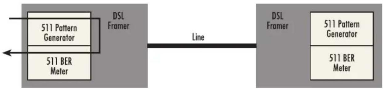
Figure 8. Local Analog Loopback diagram
The data received is looped back before going out on the DSL line. Note that this loopback occurs after the pattern generator/BER meter. This means that running a 511 pattern in conjunction with an LAL should result in no error detected by the meter.
The data path for the RDL is shown in Figure 10.

The RDL causes the remot unit to loop the data received from the DSL line back tow the DSL line.
4.3.2 Patterns
The LB510A-R2 can generate and detect 511 patterns. These can be initiated either by the middle DIP switch or by the console command dsl set pattern
Because the BER Meter always runs when the pattern generator runs, the meter will detect errors if either the pattern is not either looped back or the remote unit is not transmitting a 511 pattern.
The PC user (near-end) may configure and verify status of the remote LB510A-R2 (far-end) via a Remote Console session. The PC user must log onto the LB510A-R2 (near-end) unit to establish a remote console session. Once done, the remote LB510A-R2 (far-end) appears as a unit which is locally connected through the console port. All commands are transmitted over the G.SHDSL link in the EOC channel.
![graph LR A["PC (Near End)"] -->|Remote Console Session (RCS)| B["LB510A-R2 (Near End)"] B -->|DSL| C["LB510A-R2 (Far End)"] A -->|RJ-45| B](/content/2026/05/1048614/images/7f1dda5fe1c72cebb9a43f850c81fd2aca3a004473dd40302891b96ebf3440d7.jpg)
Figure 10. Remote control session diagram
5.1 ESTABLISHING A REMOTE CONSOLE SESSION
5.1.1 How to Connect
The following steps are to establish a connection to the remote LB510A-R2 (far-end) via Remote Console Session (RCS):
- Connect to the console port of the LB510A-R2 (near-end) via Telnet session.
- At the password prompt, log in to the near-end LB510A-R2.
- Ensure that a DSL link is established. You can verify an established DSL link by using the system show status command or by checking that the DSL LED is solid green. Upon executing the show status command, the dsl link state is shown as success if the DSL link is established.
- At the command prompt, enter the command remote console.
- Wait for the message Console: Remote console connection established.
-If a DSL link is not established, or for some other reason the LB510A-R2 (far-end) does not respond in a reasonable amount of time, the following message appears: Console: Remote console timed out trying to connect. Enter the command remote console again.
-If LB510A-R2 (Far End) already has an active remote console session open, you will see the message Console: Remote console connection request rejected. This can also happen if the remote LB510A-R2 (far-end) has an established remote console session with the local LB510A-R2 (near-end) which has timed out.
- Enter the password at the password prompt for the remote console session.
NOTE: The passwords for a local console session of the LB510A-R2 (near-end) and the remote console session of the LB510A-R2 (far-end) should be different for the purpose of security.
- You should now be logged into the remote LB510A-R2 (far-end) via the remote console session. The communication with the remote LB510A-R2 (far-end) is essentially the same as having a local console connection.
NOTE: The local or remote LB510A-R2 may be CO or CPE, as long as there is one of each. Either the CO or CPE unit may accept a remote console connection.
NOTE: With a remote console session open, a user at PC (far-end) is blocked from using the local console. Upon typing anything, the LB510A-R2 (far-end) sends a message to the PC (far-end) stating Console: Remote console connection is open.
Figure 10 is a screenshot of opening a typical remote console session:
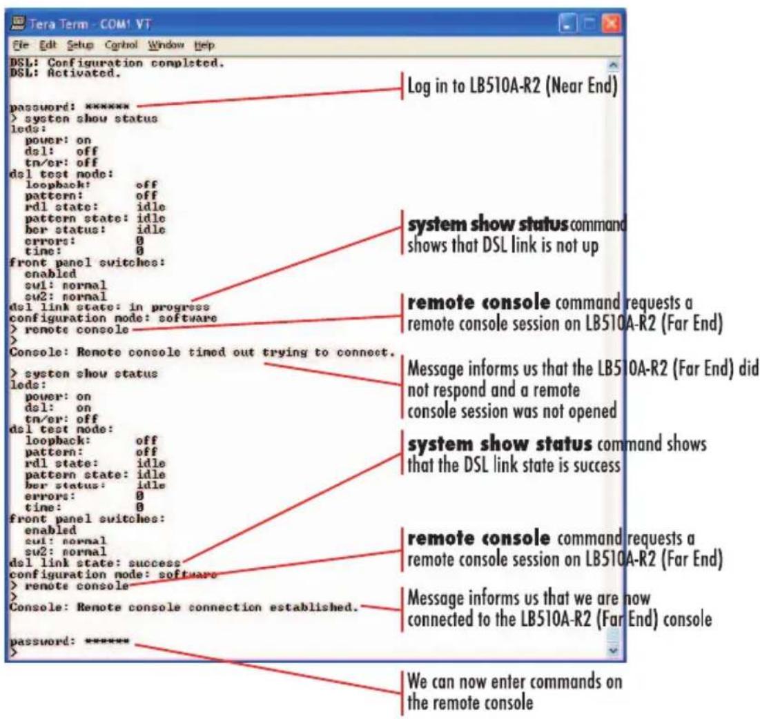
Figure 11. Opening a typical remote console session
5.1.2 How to Disconnect
The remote console session ends under any of the following conditions:
- The user enters the command logout
- A timeout period of 5 minutes elapses since the user has entered a command to the console.
- The DSL link drops.
The response upon logging out of the remote console session with the command logout is Console: Remote console connection lost. The following is what is displayed upon a user's logging out of a remote console session after logging in.
> remote console
>
Console: Remote console connection established.
password: *****
> logout
Console: Remote console connection lost.
>
The timeout period is a fixed, non-configurable parameter of 5 minutes. If the remote LB510A-R2 (far-end) has received no command within 5 minutes, it automatically terminates the RCS. Once the RCS is terminated, the PC (far-end) can establish a local console session if desired. However if the PC (near-end) wishes to re-establish a RCS, it is able to do so whether or not the PC (far-end) is in an active local session, because the RCS has priority over a local console session. If the PC (near-end) establishes an RCS while the PC (far-end) is on a local session, the PC (far-end) is kicked off.
5.1.3 Differences in local and remote control session behavior
Since the remote console session communication occurs over the G.SHDSL link's EOC channel, some commands via the RCS have unusual effects.
![graph LR A["PC (Near End)"] --> B["LB510A-R2 (Near End)"] B --> C["LAL"] C --> D["PC (Far End)"] E["Remote Console Session (RCS)"] --> A F["DSL"] --> C G["DSL"] --> C H["DSL"] --> C I["DSL"] --> C J["DSL"] --> C K["DSL"] --> C](/content/2026/05/1048614/images/33300e6ca61ca9bbb2ad63a01a8714f24505ccc9c1c564f33dc613d96d39e3f6.jpg)
Figure 12. Remote control session with LAL diagram
- dsl set loopback lal: do not issue this command over the RCS to the far-end LB510A-R2. if the far-end goes into Local Analog Loopback (LAL), the near-end and far-end LB510A-R2 NTU's can no longer communicate over the RCS.
Do not issue this command to a far-end unit. if you were to do so, the near-end LB510A-R2 would no longer be able to communicate with the far-end LB510A-R2.
6. SOFTWARE UPGRADE
The software upgrade feature is available through BOOTP/TFTP. The software upgrade takes approximately 2-3 minutes to complete. To upgrade the software:
- Connect to the LB510A-R2 via the Ethernet management port and a Telnet session.
- Enter the system show info command to view the unit's MAC address.
- Configure a BOOTP/TFTP server and enter the system upgrade / yes command to begin the upgrade.
- Alternatively, you may enter the system upgrade
:/ command to begin the upgrade.
After approximately 2-3 minutes, the LB510A-R2 will operate with the upgraded software.
7. RESET CONFIGURATION TO FACTORY DEFAULTS
The configuration can be reset to factory defaults using DIP switch S1. A factory reset allows a user to recover from a forgotten password. To reset to the configuration:
- Turn the LB510A-R2 off.
- Turn the S1-1 switch to the ON position.
- Turn the LB510A-R2 on.
- Turn the S1-1 switch to the OFF position.
A. SPECIFICATIONS
A.1 CLOCKING MODES
Internal, external or receive recovered
A.2 DTE RATE
All 64k steps from 64 to 5696 kbps
A.3 ETHERNET INTERFACE
- Four RJ-45
- 10/100base-t
- IEEE802.3 Ethernet
A.4 DIAGNOSTICS
V.52 compliant (511) pattern generator and detector with error injection mode controlled by front-panel switch. Local and Remote Loopback control either by a front-panel switch or from the DTE interface.
A.5 STATUS LED
A.5.1 POWER (GREEN)
The Power LEDglows solid during normal operation. At startup, during the POST, the LED blinks once every second. if the POST fails, the unit does not enter normal operation, and the LED blinks once every 0.4 seconds.
A.5.2 DSL (GREEN)
The DSL LED glows solid while a DSL link is established. While the DSL link is training, it blinks once every second.
A.5.3 LINK (GREEN)
The Link LED shows that there is an active physical network connection to the Console or an Ethernet device.
A.5.4 ACTIVITY (GREEN)
The Activity LED shows that there is data being transferred over that port. During a software upgrade procedure, if the Activity LED is on for extended time, a problem with the upgrade has occurred and the device should be restarted. The TFTP server should be checked (normal upgrades take about 10 seconds on a 100mbit link).
A.6 CONFIGURATION
Configuration is done with either externally accessible DIP switches, CLI or through the EOC (Embedded Operations Channel) from a LB510A-R2 G.SHDSL DSLAM.
A.7 POWER AND POWER SUPPLY SPECIFICATIONS
The CPE comes with either an AC or DC power supply;
- The supply's connection to the CPE is a 2.5 mm barrel receptacle with the center conductor positive.
- There is one fuse in the equipment rated at 250V, 500 mA, 2 sec.
- Rated voltage 5 VDC
- Rated current 1 A DC

Figure 13. Power connections barrel receptacle 5 VDC diagram
A.7.1 EXTERNAL AC UNIVERSAL POWER SUPPLY
WARNING
The external AC adaptor shall be a listed limited power source that incorporates a disconnect device and shall be positioned within easy reach of the operator. Ensure that the AC power cable meets all applicable standards for the country in which it is to be installed, ad that it is connected to a wall outlet which has earth ground.
• Output from power supply 5 VDC, 2A
- Input to power supply universal input 100-240 VAC 50/60 Hz 0.3A
A.7.2 EXTERNAL 48 VDC POWER SUPPLY

WARNING
The external DC adaptor shall be a listed limited power source that incorporates a disconnect device and shall be positioned within easy reach of the operator. The interconnecting cables shall be rated for the proper voltage, current, anticipated temperature, flammability, and mechanical serviceability.
- Input
-Rated voltage 36–60 VDC
-Rated current 0.25 A DC - Output
-Rated voltage 5 VDC 5%, 5W
-Rated current 1 A DC
• Isolation 500 VDC ± 5%, 5W
-6-inch cable terminated with 2.5 mm barrel plug, center positive
- Environment 0–40°C; 5–95% relative humidity, non-condensing
A.8 TRANSMISSION LINE
Single Twisted Pair
A.9 LINE CODING
TC-PAM (Trellis Coded Pulse Amplitude Modulation
A.10 LINE RATES DSL LINE
All nx64 rates from 192kbps up to 5.696 Mbps
A.11 LINE INTERFACE
Transformer coupled, 2500 VRMS isolation
A.12 G.SHDSL PHYSICAL CONNECTION
RJ-45, 2-wire polarity insensitive pins 4 and 5
A.13 TEMPERATURE RANGE
32-122°F (0-50°C)
A.14 HUMIDITY
5–95% non-condensing
A.15 ALTITUDE
0–15,000 feet (0–4,600 meters)
A.16 DIMENSIONS
6.22 W x 1.25 H x 4.75 D in. (157 W x 318 H x 120 D mm)
A.17 THIRD PARTY SOFTWARE LICENSES
NOTE: the LB510A-R2 includes software developed under third party licenses. contact black box for more information.
B. FACTORY DEFAULT VALUES
B.1 FACTORY DEFAULT VALUES FOR SOFTWARE-CONFIGURABLE PARAMETERS
NOTE: The default management IP address is 192.168.200.1.
NOTE: The default logout timer value is set for 300 seconds (5 minutes).
| Parameter Default value | |
| DSL Timeslots | 89 |
| Circuit ID Black Box LB510A-R2 | |
| Password | superuser |
| Annex B | |
| Management | In-band |
| DSL Mode CPE | |
C. INTERFACE PINOUTS
C.1 LINE PORT
C.1.1 RJ-45
- Pin 4: Tip
- Pin 5: Ring
- Pins 1, 2, 3, 6, 7, 8: no connection
C.2 ETHERNET PORT
C.2.1 RJ-45 SOCKET 10/100BASE-T
- Pin 1: TX+
- Pin 2: TX-
- Pin 3: RX+
- Pin 6: RX-
NOTE: Pins not listed are not used.
Black Box Tech Support: FREE! Live. 24/7.
Tech support the way it should be.

Great tech support is just 30 seconds away at 724-746-5500 or blackbox.com.

BLACK BOX®
NETWORK SERVICES
About Black Box
Black Box provides an extensive range of networking and infrastructure products. You'll find everything from cabinets and racks and power and surge protection products to media converters and Ethernet switches all supported by free, live 24/7 Tech support available in 30 seconds or less.
© Copyright 2012. Black Box Corporation. All rights reserved. Black Box® and the Double Diamond logo are registered trademarks of BB Technologies, Inc. Any third-party trademarks appearing in this manual are acknowledged to be the property of their respective owners.


- TABLE OF CONTENTS
- GENERAL INFORMATION 9
- CONFIGURATION.... 11
- INSTALLATION 23
- OPERATION.... 25
- REMOTE CONSOLE OPERATION.... 28
- RADIO FREQUENCY INTERFERENCE STATEMENTS
- FEDERAL COMMUNICATIONS COMMISSION AND INDUSTRY CANADA RADIO FREQUENCY INTERFERENCE STATEMENTS
- SAFETY WHEN WORKING WITH ELECTRICITY
- GENERAL INFORMATION
- 1.1 FEATURES
- 1.2 DESCRIPTION
- 1.3 POWER INPUT CONNECTOR
- 1.3.1 EXTERNAL AC UNIVERSAL POWER SUPPLY
- 1.3.2 EXTERNAL 48 VDC POWER SUPPLY
- INPUT
- OUTPUT
- CONFIGURATION
- 2.1 SOFTWARE (CLI) CONFIGURATION
- 2.2 HARDWARE (DIP-SWITCH) CONFIGURATION
- 2.3 CONFIGURING THE DIP SWITCHES
- 2.4 SYSTEM RESET MODE
- 2.5 DIP SWITCH SETTINGS
- 2.5.1 SWITCHES S4-2 THROUGH S4-8 DEFINE THE DSL LINE RATE
- 2.6.1 HELP COMMANDS
- 2.6.2 SYSTEM CONFIGURATION COMMANDS
- 2.6.3 SYSTEM STATUS COMMANDS
- 2.6.4 DSL CONFIGURATION COMMANDS
- 2.6.5 DSL STATUS COMMAND
- 2.6.6 DSL CLEAR ERRCNTRS COMMAND
- 2.7 REMOTE CONSOLE
- 2.7.1 EXAMPLE COMMAND LINE INTERFACE SESSION
- INSTALLATION
- 3.1 CONNECTING THE DSL INTERFACE
- 3.2 CONNECTING THE ETHERNET INTERFACE
- 3.3 CONNECTING POWER
- 3.3.1 EXTERNAL AC UNIVERSAL POWER SUPPLY
- 3.3.2 DC POWER
- OPERATION
- 4.1 POWER-UP
- 4.2 LED STATUS MONITORS
- 4.2.1 POWER (GREEN)
- 4.2.2 DSL (GREEN)
- 4.2.3 LINK (GREEN)
- 4.2.4 ACTIVITY (GREEN)
- 4.3 TEST MODES
- 4.3.2 PATTERNS
- 5.1 ESTABLISHING A REMOTE CONSOLE SESSION
- 5.1.1 HOW TO CONNECT
- 5.1.2 HOW TO DISCONNECT
- 5.1.3 DIFFERENCES IN LOCAL AND REMOTE CONTROL SESSION BEHAVIOR
- SOFTWARE UPGRADE
- RESET CONFIGURATION TO FACTORY DEFAULTS
- SPECIFICATIONS
- A.1 CLOCKING MODES
- A.2 DTE RATE
- A.3 ETHERNET INTERFACE
- A.4 DIAGNOSTICS
- A.5 STATUS LED
- A.5.1 POWER (GREEN)
- A.5.2 DSL (GREEN)
- A.5.3 LINK (GREEN)
- A.5.4 ACTIVITY (GREEN)
- A.6 CONFIGURATION
- A.7 POWER AND POWER SUPPLY SPECIFICATIONS
- A.7.1 EXTERNAL AC UNIVERSAL POWER SUPPLY
- A.7.2 EXTERNAL 48 VDC POWER SUPPLY
- A.8 TRANSMISSION LINE
- A.9 LINE CODING
- A.10 LINE RATES DSL LINE
- A.11 LINE INTERFACE
- A.12 G.SHDSL PHYSICAL CONNECTION
- A.13 TEMPERATURE RANGE
- A.14 HUMIDITY
- A.15 ALTITUDE
- A.16 DIMENSIONS
- A.17 THIRD PARTY SOFTWARE LICENSES
- FACTORY DEFAULT VALUES
- B.1 FACTORY DEFAULT VALUES FOR SOFTWARE-CONFIGURABLE PARAMETERS
- INTERFACE PINOUTS
- C.1 LINE PORT
- C.1.1 RJ-45
- C.2 ETHERNET PORT
- C.2.1 RJ-45 SOCKET 10/100BASE-T
- BLACK BOX®
- ABOUT BLACK BOX
Brand : Black Box
Model : LB510A-R2
Category : Wi-Fi repeater