
EC-80320 - Label printer EC Line - Free user manual and instructions
Find the device manual for free EC-80320 EC Line in PDF.


| Product Type | Label Printer |
| Brand | EC Line |
| Model | EC-80320 |
| Dimensions (W x D x H) | 220 x 150 x 130 mm |
| Weight | 1.5 kg |
| Power Supply | 100-240V AC, 50/60 Hz |
| Print Technology | Thermal Transfer / Direct Thermal |
| Print Resolution | 203 dpi |
| Print Speed | Up to 100 mm/s |
| Connectivity | USB 2.0, Serial RS-232 |
| Media Types | Labels, tags, continuous roll |
| Max Label Width | 80 mm |
| Display | 2-line LCD |
| Memory | 16 MB RAM, 8 MB Flash |
| Supported Languages | Multiple (including English, French, German) |
| Ribbon Type | Wax, resin, wax-resin |
| Sensor Type | Gap, black mark, ribbon end |
| Software Compatibility | Windows, macOS, Linux via drivers |
| Warranty | 1 year limited |
| Maintenance | Clean print head and platen roller regularly |
Frequently Asked Questions - EC-80320 EC Line
User questions about EC-80320 EC Line
0 question about this device. Answer the ones you know or ask your own.
Ask a new question about this device
Download the instructions for your Label printer in PDF format for free! Find your manual EC-80320 - EC Line and take your electronic device back in hand. On this page are published all the documents necessary for the use of your device. EC-80320 by EC Line.
USER MANUAL EC-80320 EC Line
Be sure to have read the manual seriously before your operation. Neither EC PRINTER nor its affiliates shall be liable to the purchaser of this product or third parties for damages, losses, costs, or expenses incurred by purchaser or third parties as a result of: accident, misuse, or abuse of this product or unauthorized modifications, repairs, or alterations to this product, or failure to strictly comply with EC PRINTER's operating and maintenance instructions.
☐ Follow the notices and warnings carefully to avoid seriously bodily injury.
☐ Don't touch the thermal head with your hand and other solid object at any moment to avoid your body burned or the thermal head damaged.
☐ Be careful the dentate cutter when you replace the paper.
☐ You are forbidden to clean the printer with alcohol or other liquid when the printer is connected to the power, pull the plug out when which is processed, using the soft cloth instead of the hard object.
□ Please don't use the printer near the liquid.
☐ Make sure that the printer is connected to a reliable power outlet. It should not be on the same electric circuit as copiers, refrigerators, or other appliances that cause power spikes.
☐ Make sure the printer is far away from the appliance that can arouse electromagnetic jam, such as loudhailer.
☐ The power outlet you plan to connect to should be nearby and unobstructed.
☐ Make sure that the surrounding area is clean, dry, free of dust and not exposed to direct sunlight.
- Don't remove the printer's out-cover and repair the printer. When needed, call or take it to the professional.
☐ Make sure to set the power switch OFF when connects the printer to the power or computer.
☐ When the following error or problem occurred, please contact the professional or dealer:
A: The power cable is damaged or broken.
B: The printer is sloppy by some liquid.
C: The printer didn't work when you operate according the manual.
D: The printer out-cover is broken.
E: The specification or print quality is going wrong obviously, need repaired.

Warning: In order to ensure the use life of printer, strictly prohibit printing full line full black exceed than 2 CM.
Notice: The contents of this manual are subject to change without notice.
*All the part of the printer can be recycled. When it is abandoned, we can callback it freely. Please contact us when you abandon it.
Table of contents
The Guide......i
Chapter 1 Introduction....1
1.1 Features....1
1.2 Part Description .... 1
1.3 Parts Identification .... 1
Chapter 2 Connecting Cables ....3
2.1 Unpacking....3
2.2 Unpack the Protect Materials....3
2.3 Connecting to Your Computer or Other Equipment....3
2.3.1 Connecting the Parallel Interface Cable 3
2.3.2 Connecting the Serial Interface Cable (Optional) 4
2.3.3 Connecting the USB Interface Cable....4
2.3.4 Connecting the Drawer Cable 5
2.3.5 Connecting the Ethernet Cable 5
2.4 Connecting the Adapter 6
2.5 Setup the Print Driver and Select the Cutter 6
2.6 Network Settings....9
2.6.1 Connecting Printer....9
2.6.2 Setting IP Address....9
2.6.3 Installing Printer Network Driver....12
Chapter 3 Base Control Panel Operations....19
3.1 Control Panel....19
3.1.1 Indicator 19
3.1.2 KEY....19
3.2 Self-Printing 19
3.3 HEX DUMP PRINTING....20
3.4 Restoring Factory Printer Settings....20
3.5 Setting Slip Stitch....20
3.6 Online-aptitude Parameter Settings....20
Chapter 4 Install and Replace the Roll Paper....22
4.1 Paper Installed Steps....22
Chapter 5 Features....24
5.1 General Specification....24
5.2 Interface Features....25
5.2.1 Parallel Interface 25
5.2.2 Serial Interface (Optional) 26
5.2.3 USB Interface 27
5.2.4 Drawer Connector 27
5.2.5 Power Supply Connector....28
5.2.6 Ethernet Connector....28
Chapter6 Troubleshooting and Maintenance....29
6.1 Maintenance 29
6.2 Error Message on the Control Panel....29
6.3 Cutter Jammed or Error 29
Chapter 7 Control Commands....31
7.1 General....31
7.2. Explanation of Terms ......31
Appendix Commands List 44
Chapter 1 Introduction
1.1 Features
EC80320 printer is a kind of high-speed mini thermal printer. It is a high-quality, high-reliability and low-noise POS printer and operated easily, which can be widely used in ECR, PC-POS and BANK POS for printing variety of receipt.
1.2 Part Description
According different data port (interface), EC80320 serials are divided into several different names: EC80320 is the printer equipped with parallel interface, EC80320US is equipped with serial interface and USB interface, EC80320U is equipped with USB interface and EC80320UE with Ethernet interface and USB interface.
EC80320 serials printer is equipped with auto cutter. It have two kinds of cutter for the consumer to selected: partial cutter can only cut the paper with one point left while full cutter cuts the paper fully.
| Parallel interface | USB interface | USB + Serial interface | USB + Ethernet interface. | |
| MODEL | EC80320 | EC80320U | EC80320US | EC80320UE |
Note: Please contact with the dealer for changing the interface if needed.
1.3 Parts Identification
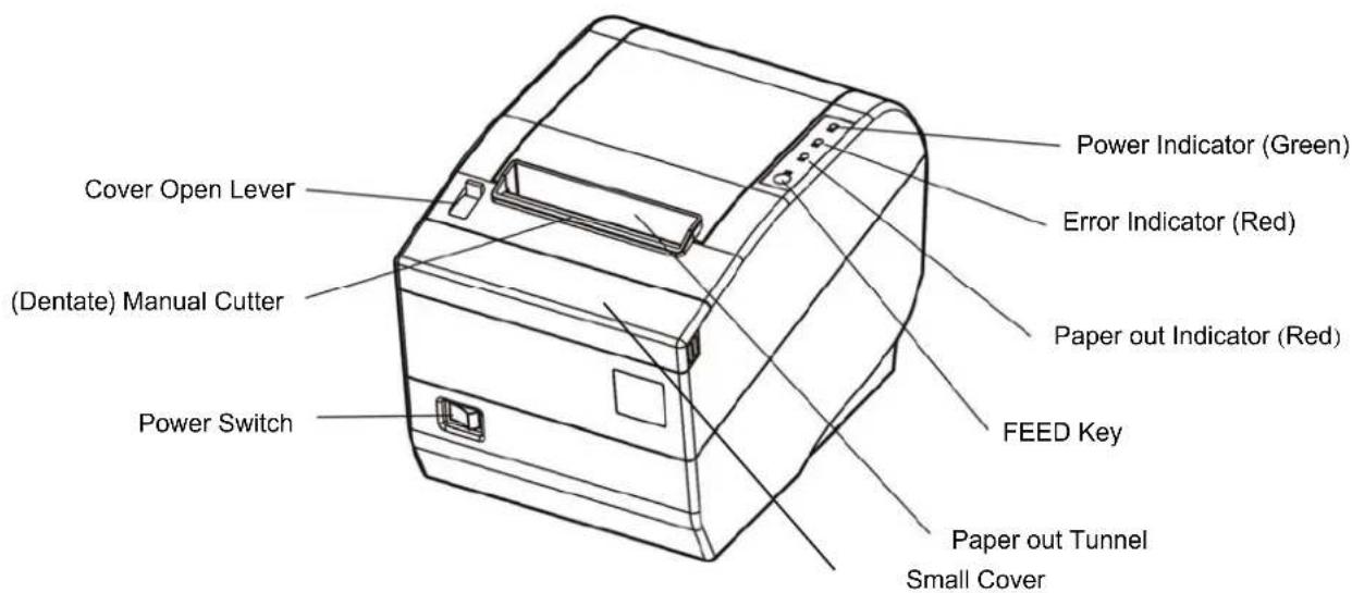
Fig1-1 Main part of the printer

Fig1-2 Back of the printer
Chapter 2 Connecting Cables
2.1 Unpacking
Check each item against the following packing list. If any of these items are missing. Please contact your dealer.
The interface cable is optional, which will be equipped or cancelled according the customer's request.
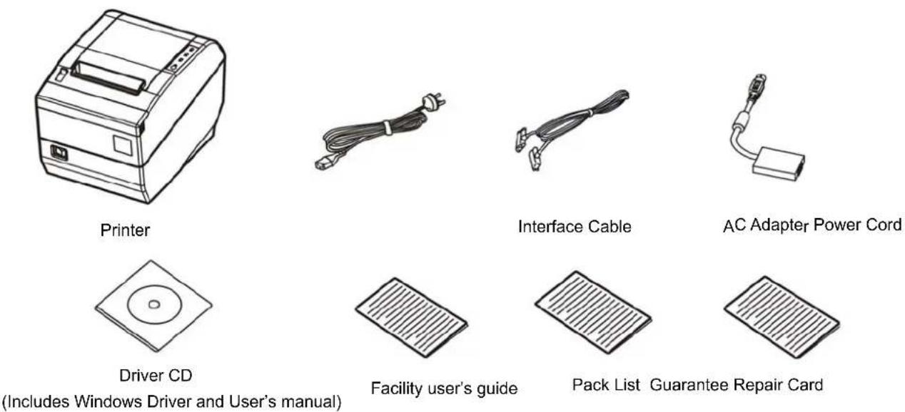
Fig2-1 Packing List
2.2 Unpack the Protect Materials
- Open the packing box, lift up the printer.
- Save all the original packing materials, so that it can be used when to transport the printer.
2.3 Connecting to Your Computer or Other Equipment
Note: Before connecting/disconnecting the interface cable, make sure that power to the printer and all the devices connected to the printer are turned off. Also make sure the power cable plug is disconnected from the AC outlet.
2.3.1 Connecting the Parallel Interface Cable
- Make sure the Host and the printer are both turned off, connect the parallel interface cable to the connector on the rear panel of the printer, fasten the connector clasps as shown in Fig 2-2.
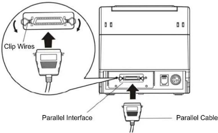
Fig 2-2 Connecting the parallel interface cable
-
Connect the other end of the cable to the host. Tighten the connector screws.
-
This printer can carry out a network printing through connecting parallel interface to network print server, which you can use are PS-1206, SX-110 and SX-3100 which have been validated.
2.3.2 Connecting the Serial Interface Cable (Optional)
- Make sure the Host and the printer are both turned off, connect the serial interface cable to the connector on the rear panel of the printer. Tighten the connector screws as shown in Fig 2-3.

Fig2-3 Connecting the serial interface cable
- Connect the other end of the cable to the host's serial connector and tighten the connector screws.
2.3.3 Connecting the USB Interface Cable
-
Plug the USB cable A end (square shape) into the printer's USB connector as shown in Fig2-4.
-
Plug the other end of the USB cable (flat) to the computer's USB connector.

Fig2-4 Connecting the USB interface cable
2.3.4 Connecting the Drawer Cable
Turn off the printer and plug the drawer cable into the drawer connector on the back of the printer as shown in Fig2-5.
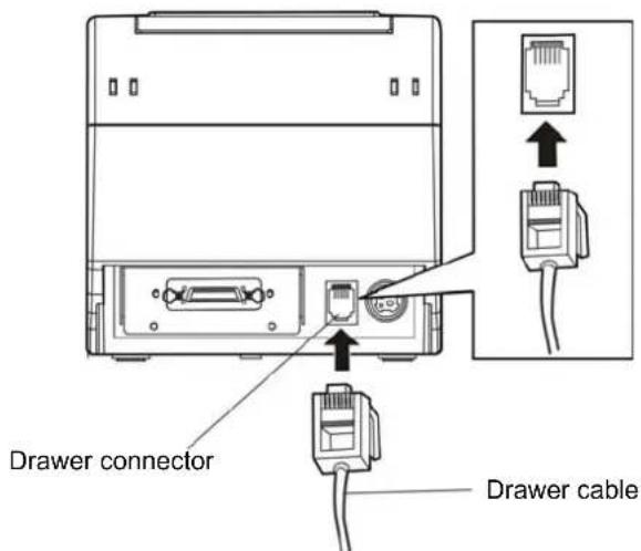
Fig2-5 Connecting the Drawer cable
Warning: Don't connect a telephone line to the drawer connector; otherwise both the telephone line and the printer may be damaged.
2.3.5 Connecting the Ethernet Cable
- Plug the crystal end of the Ethernet cable (RJ-45) into the printer's Ethernet connector as shown in Fig2-6.
- Plug the other end of the Ethernet cable (flat) to the LAN's entrance.
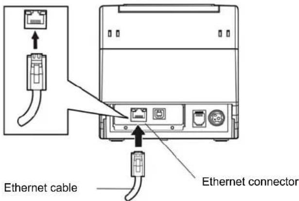
Fig2-6 Connecting the Ethernet cable
2.4 Connecting the Adapter
- Make sure the printer's power switch is turned off. Plug the adapter's supply cable as shown below. Connect the adapter to the power cord.
- Make sure the voltage of the electrical outlet matches that of the adapter.
- Plug the adapter to the printer's electrical outlet.
- Plug the power thread one end to the adapter and the other to the AC outlet with ground wire.
Note: 1. If the voltage of electric outlet isn't within the scope marked in the label, please contact your dealer for solution, and must not connect the power cord to the wall outlet.
- Please use the exactitude electrical outlet with ground wire.
- Make sure to use EC PRINTER original adapter, or we will not assume to take ability for the printer damage.

Fig2-7 connecting the adapter
2.5 Setup the Print Driver and Select the Cutter
You must setup the printer driver in Windows before using the EC80320 printer.
Please use the cable to connect computer with printer, then turn on the computer and the printer, put the drive CD into the CD-ROM. Install driver by the following way:
Auto-install way
Double click the file "Setup.exe" in the driver disc, install driver by the following direct.
Hand operated installing way
1) The installing steps for Windows 2000/XP are as follows:
- Click "Start" --> "Settings", select "Printers".
- Click "Add Printer", then it will show a window of "Add Printer Wizard", click "Next", then please read the select direct carefully, Such as, select "Local printer" in the "Local or Network Printer" window, then click "next".
- Come out a window of "Select the Printer Port", select a usable port. Such as, select "LPT1: printer port", click "Next".
- Come out a window of "Manufacturers/Printers", click "Have Disk...", click "Next".
- Come out a window of "Install From Disk". Please according to the operating system environment, such as Windows XP operating system you should select the path as follow: CD-ROM-"Driver"-WIN2000(XP-Vista)", which you can find a file named: EC80320.inf, click "Open", then click "OK" to return to the window of ""Manufacturers/Printers", click "Next".
- Follow the direct click "Next" gradually till the installation is finished.
2) The installing steps for Windows 7 are as follows:
- Click "Start" -->"Settings and Printers".
- Click "Add Printer", then it will show a window of "Add Printer Wizard", click "Next", then please read the select direct carefully, Such as, select "Local printer" in the "Local or Network Printer" window, then click "next".
- Come out a window of "Select the Printer Port", select a usable port. Such as, select "LPT1: printer port", click "Next".
- Come out a window of "Manufacturers/Printers", click "Have Disk...", click "Next".
- Come out a window of "Install From Disk". Please according to the operating system environment, such as Windows XP operating system you should select the path as follow: CD-ROM-"Driver"-WIN2000(XP-Vista)", where you can find a file named: EC80320.inf, click "Open", then click "OK" to return to the window of "Manufacturers/Printers", click "Next".
- Follow the direct click "Next" gradually till the installation is finished.
Please setup the driver following the setup description in the CD going along with the printer. What's more, you can use the TM-T88II, TM-T88III serials driver from EPSON.
If you want to cut the paper after printing, please select the "Full cut" or "Partial cut" in the Paper/Quality page after clicking the "Printing Preferences" button, which lies in the "General" page of the driver properties. Referring figure is shown below.
It is noted that if paper cut effect is the same whichever you select "full cut" or "partial cut" in the driver properties, which means that the cutter (the printer equipped with) can only carry out one kind of cut-method.

Fig2-8 EC80320 Printing Preferences
The following condition may cause the printer can't cut paper properly in Win2000/XP (or updated version).
- You do not setup the driver with the document setup.exe in the CD. Instead, you follow the Windows' installation guide.
- Once you connect a printer with a parallel or serial port, but online with USB port Later, which may cause a WINDOWS setup duplicate driver.
Only when the driver property is modified manually after being installed during the condition mentioned above, does the cut- method take effect.
If you find the driver couldn't cut paper, modify the driver property as shown below.
(1) cancel the "√" in the pane before the "Enable advanced printing features" in the "advanced" page.
(2) Then click the "Print Processor" button as shown below. Enter the "Print Processor" dialogue box, select the "JMProces" and "RAW", and click the "OK" button.

Fig2-9 Modify the driver property
2.6 Network Settings
Please use EC PRINTER network setting software NetFinder to set the IP address for EC PRINTER printers, which can be found in the CD or downloaded from EC products web site.
2.6.1 Connecting Printer
Power on the printer, connect with the Ethernet cable which has been connected to LAN, and look into the information of Ethernet LED indicator to ensure the printer has entered into the normal connection.
| Yellow LED Green LED Description | ||
| ON | Flash | |
| OFF OFF Not connect to network | ||
Normal
2.6.2 Setting IP Address
1. Run NetFinder Software
Double click NetFinder.exe in the PC which connects the printer in the same LAN. The figure of the software is shown as follows:

Fig2-10 Run NetFinder Software
Button description:
Exit—Exit from the software
Search—Search printers in the same LAN
Assign IP—Modify the IP address and other settings for the specified printer.
2. Search printer
Click "Search" button in the main interface, the dialog box appearing will begin searching automatically and show appearance, listing a printer in the main interface if found. The time is counting down in the progress bar (10s in total) and the search will finish as soon as the time is over. When going on searching, press "search" button again.
![NetFinder v1.1 EC-80320 EC Printer IP Address: 192.168.0.240 [Static] MAC Address: 20-2C-B7-00-3F-03 Exit Search... time left 6 second(s) found 1 device(s) Reload Timer Close this window when searching completes Stop OK](/content/2026/05/988358/images/6a573580344291f4e718f3086108638817f44facd6be0b5714716eb0b70655f2.jpg)
Fig2-11 Search printer
If the printer still can not be found out when the network connection is correct in the same network, Please check whether the network fire wall on the PC open or not. If there is fire wall, please close it temporarily, open again after finishing searching and setting a printer completely.
3. Setting printer's IP address
The printer's information is listed in the main interface, the left side of which is the model and description and the right is the IP and MAC address. What's more, the assign mode (dynamic/static) is noted behind the IP address.
![NetFinder v1.1 EC-80320 IP Address: 192.168.0.240 [Static] EC Printer MAC Address: 20-2C-B7-00-3F-03 Exit Search Assign IP](/content/2026/05/988358/images/8ed3cf9f601f11de629de4d3afb5b616c672055523e331ad3ba5c3bb4f566a72.jpg)
Fig2-12 Setting printer's IP address
1) Correlative description for IP address settings
In order to search and set printer's IP address conveniently for the first time, the factory default setting is DHCP mode which assigns IP address dynamically. If there is no DHCP server in the connected LAN and printer is set to DHCP mode as well, then it will use the internal pre-set address (IP: 10.0.0.1, Subnet Mask: 255.255.255.0) automatically.
It is suggested that printer's IP set to static in actual usage, which can cut down the time when initializing the Ethernet interface as the printer is turned on and prevent IP conflicts (The dynamic address used in printer may conflict with another one). The network segment part of the IP address and Subnet Mask must be the same as those of PC connecting with a printer.
For example, the address of working PC is 192.168.0.1/255.255.255.0 (IP/Subnet Mask), then which of printer should be set to 192.168.0.x/255.255.255.0 (x=2\~254 and should avoid the IP in used. It is not restricted for NetFinder to search printers in the same network but different segment parts (can not stride gateway). Relative glossary of IP address may refer to corresponding information.
2) Setting printer's IP address
Select the printer information to be modified (black frame appears), click "Assign IP" button. Set the IP in the dialog box appearing.
Check the "Use DHCP" if need to assign dynamic address, the settings above will be disabled
automatically. Please make sure there is a DHCP server in the network, or the printer can not receive an effective IP address.
When to specify static address, uncheck "Use DHCP" and fill in "IP address", "Subnet Mask" and "Default Gateway". If there is no gateway in the network, fill 255.255.255.255 in the "Default gateway". "IP address" and "Subnet Mask" should obey the assigning rules of local LAN (Ethernet), please enquire the administrator of networks which the printer connects to for more details.
Click "OK" to send address setting information to the specified printer. The printer takes response after "Close this window on success" is checked, and then this dialog is closed automatically. Select "Reload Timer" then the software will wait for the printer's response. Generally, printer will take response in a circle time if network connection is correct.
Click "Cancel" if you abandon the modification.
Click "Search" in the main interface again to update printer information after modifying the printer's IP address.
3) Report printer's IP address
Report the printer's IP address, which will be used in the section "Newly-install printer network driver" or "Upgrade-install printer network driver (setting driver's network port)".
2.6.3 Installing Printer Network Driver
The ways of installing network driver are divided into Newly-install way and Upgrade-install way according to whether the PC installs the printer driver or not.
If the printer driver hasn't been installed on the PC, adopt newly-install way whose steps are shown in "Newly-install printer network driver".
If the printer driver has been installed on the PC, adopt Upgrade-install way whose steps are shown in "Upgrade-install printer network driver".
1. Newly-install printer network driver
1) Click "Start"→"Settings", select "Printers.
2) Click "Add printer", then come out a window of "Add Printer Wizard", click "next", then please read the select direct carefully. Such as, select "local or Network Printer", then click "next".
3) Come out a window of "Select the Printer port", select a port you want your printer to use. For example, select "Create a new port", select "Standard TCP/IP Port" in the port, click "next".
4) Come out a window of "Add standard TCP/IP Printer Port Wizard", click "Next".

5) Come out a window of "Add Port", enter the IP address reported by the "Setting printer's IP address" in the "Printer Name or IP Address" column. Take IP address "192.168.0.240" for example. "Port Name" is created automatically after finishing filling in IP address.
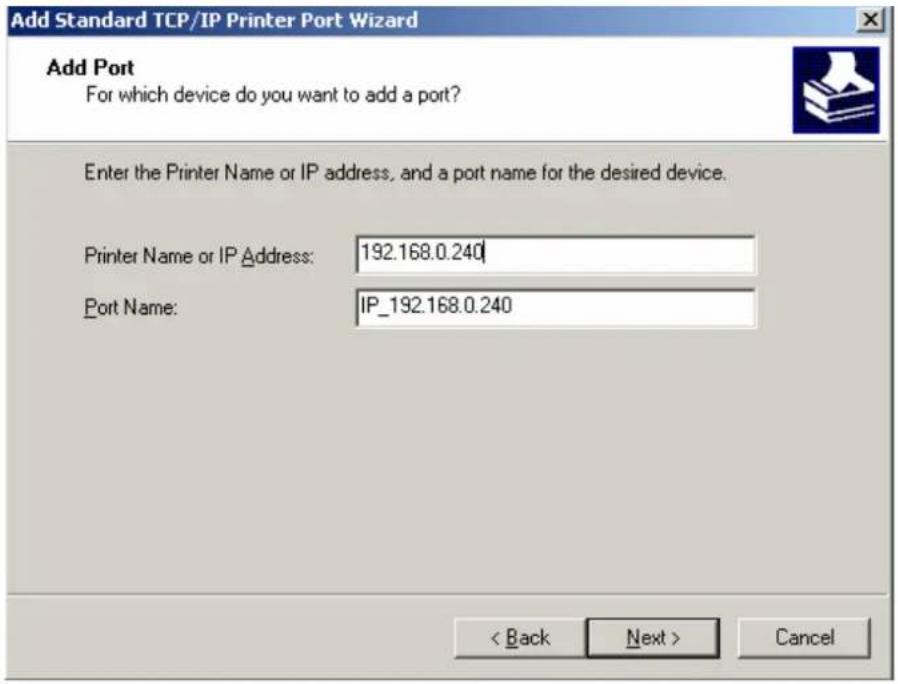
6) Come out a window of "Additional Port Information Required", select "Custom" in the "Device Type", then click "Settings".

7) Come out a window of "Port Settings". Affirm that "Port name" and "Printer name or IP address" are correct, "Protocol" is "RAW" and "Port Number" is "9100", click "OK".

8) Return to "Additional Port Information Required", click "Next".
9) Come out a window of "Completing the Add Standard TCP/IP Printer Port Wizard", click "Finish".
10) In the selection of "Manufacturers/Printers", click "Have Disk", and then click "Next".
11) Come out a window of "Install From Disk". Please according to the operating system environment, such as Windows XP operating system you should select the path as follows: CD-ROM-"Driver"-WIN200(XP-Vista)", that you can find a file named: EC80320.inf, click "open", then click "OK", then return to the window "install printer software", click "next".
12) Follow the direct click "next" gradually till the installation is finish. At this time, printer network driver is installed completely.
2. Upgrade-install printer network driver (setting driver's network port)
If PC has installed the printer's driver, set driver's network port to carry out network printing. The concrete steps are shown below:
1) Click "Start"→"Settings", select "Printers"
2) Right click EC80320 driver, click "Properties" on the window coming out.
3) Come out a window of "Properties", click "Ports" and "Add Ports".

4) Come out a window of "Printer port", select "Standard TCP/IP Port", click "New port".

5) Come out a window of "Add Standard TCP/IP Printer Port Wizard", click "Next".
6) Come out a window of "Add a port", import the IP address reported by the "Setting printer's IP address" in the "Printer name or IP address" column. Take IP address "192.168.0.240" for example. "Port name" is created automatically after finishing filling in IP address. Click "Next".
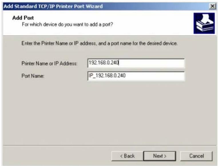
7) Come out a window of "Port information", select "User-defined" in the "Equipment style", then click "setting". Come out a window of "Additional Port Information Required", select "Custom" in the "Device Type", then click "settings".

8) Come out a window of "Port Settings". Affirm that "Port name" and "Printer name or IP address" are correct, "Protocol" is "RAW" and "Port Number" is "9100", click "OK".

9) Return to "Additional Port Information Required", click "Next".
10) Come out a window of "Completing the Add Standard TCP/IP Printer Port Wizard", click "Finish".
11) Return to "Printer Ports", click "Close

12) Return to "Properties", make sure the network port is selected, click "Apply", and then click "Close". Thus, printer's network port setting is finished.

Chapter 3 Base Control Panel Operations
3.1 Control Panel
There are three light indicators and one key on the control panel shown as Fig 3-1.

Fig3-1 Control panel
3.1.1 Indicator
| Indicator | Description |
| POWER | Indicate whether the printer's power supply is connected or not. The indicator is on when the power is connected. |
| ERROR | Indicate printer's state. The indicator is on when the abnormality appears. |
| PAPER OUT | Indicate printer's paper state. The indicator is on when paper end or near end. |
*Refer to 6.2 Error message on the control panel
3.1.2 KEY
| Key | Function |
| 【FEED】 | 【FEED】controls paper feeding, you can enable or disable the button's function with a command. When enable, the paper will be fed continuously if you press and hold on it, or stopped if you loosen it. |
3.2 Self-Printing
Self-printing lets you know if the printer is working properly. If the printer printouts the self-test content normally, it can be indicated that there is nothing wrong with the printer except for the interface connecting to the host. Otherwise, the printer should be repaired.
Before self-test printing, make sure the power is turned off and the printer is closed properly. Hold down the FEED button and turn on the power switch while the printer cover is closed. Press FEED button and Power on the printer, the ERROR indicator blinks with two beeps (if beeper is installed in the printer), loosen the button, then the printer will print out self-test information such as the software version, update date and interface etc.
3.3 HEX DUMP PRINTING
This function allows you to check whether the connection between the printer and the host or terminal device works properly or not.
The method is that press FEED button and power on the printer, the ERROR indicator blinks once with two beeps. Go on holding the button for about a second, loosen it after the ERROR blinks once again with a beep. Turn off the printer when you want to exit this print mode.
3.4 Restoring Factory Printer Settings
The function is to clear the settings stored in the printer and restore the factory settings for correlative parameters.
The method is that press FEED button and power on the printer, the ERROR indicator blinks once with beeping twice at the same time. Do not loosen the button until the ERROR indicator blinks twice with beeping twice in two seconds. At this time, turn off the printer and the function takes effect.
3.5 Setting Slip Stitch

Fig3-2 Setting slip stitch
If needed, Slip Stitch is used to upgrade printer firmware or it should be closed in normal working condition. When to upgrade, pull out the Slip Stitch Cap after the printer is turned off, press FEED button and power on again, the ERROR and PAPER OUT indicator blinking once at the same time, which indicates that the printer enters into the online-upgrade mode. Loosen the button and then use the computer software equipped with the printer to upgrade. Turn off the printer after finishing upgrading, plug Slip Stitch Cap and then the printer can be working normally.
Note: Do not change the Slip Stitch without any permission of the factory, or the printer can not work.
3.6 Online-aptitude Parameter Settings
EC80320 supports the function of online-aptitude parameter settings, which can be set in the PC with the driver installed in. The parameter settings of serial interface can be modified in the driver's property page.
The concrete setting steps are shown as follows:
- Make sure that the host and the printer are connected with a cable and both the host and the printer is turned on, the printer should be online as well.
-
Click "Start"→ "Settings"→ "Printers"
-
Right click "EC80320", select "Properties".
- Click "Printer settings" in the property page.

Fig3-3 Parameter settings
- Check whether the selected port in the "Ports" is matched with the port connecting to the printer in practical. Return to "Device Property" page layout, the list in the left are the items you want to set and the right are the item's parameters. If you only want to change one item, click "Set Item", or if you want to change multiple items, click "Set All Item" after having set all items. The settings are saved with the printer beeping once.
Note: The parameter settings shown in the "Device Property"
- After finishing settings, click "OK", exit the "Properties" window.
- Startup the printer.
Chapter 4 Install and Replace the Roll Paper
The printer can install the paper conveniently, which should be 80mm width. How to deal with the paper will be explained in details in this chapter
4.1 Paper Installed Steps

Note
- Don't touch the thermal head after printing to avoid being burned.
-
Don't pull the paper moving directly with your hand.
-
Push the cover open lever, open the cover.
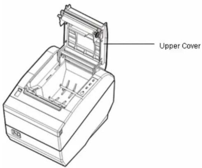
Fig 4-1 Open the cover
- Insert the paper roll as shown below (Be sure to note the correct direction that the paper comes off the roll).

Fig4-2 Insert the paper roll
Note: Paper head should be pulled out by the direction of paper-input slot, but not the opposite.
- Pull out a small amount of paper as shown in Fig 4-3.
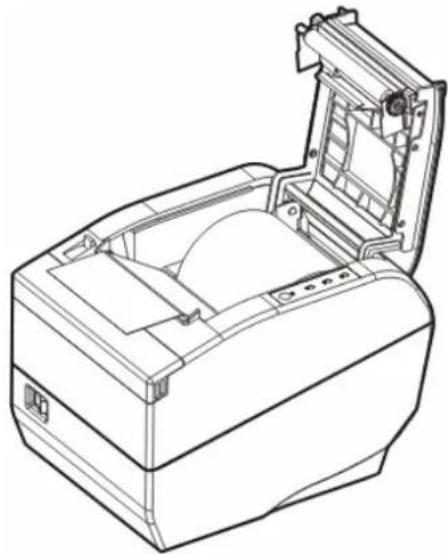
natural_image
Line drawing of a printer with open lid and internal compartments (no text or symbols)Fig 4-3 Pull out the paper
- Put the paper as shown below, and then close the cover.

natural_image
Line drawing of a generic printer or scanner device (no text or symbols visible)Fig 4-4 Close the cover
- If you have connected the cable, turn on the power and then the printer is ready.
NOTE: After finishing installing the paper, if PAPER OUT indicator and ERROR indicator are still on, or the printer rattle when feeding the paper, please open the cover and re-close it tightly.
Chapter 5 Features
5.1 General Specification
| Item Description | |
| Print method Direct thermal printing | |
| Print direction Line printing | |
| Paper width 72 mm | |
| Print speed 220mm/s (52line/s) | |
| Print head Lifespan: 100 Km | |
| Resolution 8 dot/mm, 576dot/line, 203DPI | |
| Character set | ASCII: 13 international character setsChinese: GB 18030 |
| Code page 9 kinds | |
| Bard code | UPC-A、UPC-E、EAN-13、EAN-8、Code39、Code128、ITF-25、Codabar |
| Life space | 1/6 inch, or programmable in 1/203 inch increments |
| Paper feed speed 220 mm/s at most | |
| Emulation | ESC/POS |
| Interface | Parallel interface (Centronics) + Drawer interface (CPC6)USB interface (2.0 Full-Speed) + Drawer interface (CPC6)USB interface (2.0 Full-Speed) + Serial interface (RS-232C) + Drawer interface (CPC6)USB interface (2.0 Full-Speed) + Ethernet interface (10/100Base-T) + Drawer kick-out interface (CPC6)*Only equip with one assembled interface when leaving factory. |
| Buffer | 4MB |
| Noise | <38 dB (A) |
| Control panel | The control panel consists of one key and three LED indicators. |
| Paper type | Thermal roll paper |
| Paper specification | Thermal roll paper model: TF50KS-E (Japan paper co.ltd)AF50KS-E (JUJO THERMAL)Width: 79.5 ± 0.5 mmWeight: 53 ~ 80 g/m2Maximum diameter: 80 mm*Suggestion: Inner diameter of paper shaft:12mm, Outer diameter of paper shaft:18mm |
| Physical dimensions | 145 mm (Width) × 200 mm (Depth) × 145 mm (Height) |
| Weight | About 2Kg |
| Environmental conditions | Operating environment: temperature: 5 ~ 50°CHumidity: 10%RH ~ 80%RH (No condensation) |
| Storage environment: temperature: -20 ~ 60°CHumidity: 10%RH ~ 90%RH (No condensation) | |
| Power requirements | Input voltage: 176 ~ 242 VFrequency: 50Hz/60Hz |
| Output voltage: DC24 V | |
| Electricity: 2.5 A | |
| Power consumption | Operation: 40 W; max: 180 W; standby: 2.9 WNote: Only when the product doesn't connect any power supply, can it consume zero energy. |
| Reliability | MCBF: 52 million lines |
| Lifespan of cutter: ≥1 million cut | |
| Safety criterion | GB 4943-2001 |
| EMI | Class B |
| Star of energy resourceV1.1 | Accord |
| Authentication | CCC authentication |
| Specified function | Online parameter settings |
| Paper feed width | 79.5 ± 0.5 mm |
| Max paper thickness | 0.065 ~ 0.15 mm |
| Black mark | Match |
5.2 Interface Features
The printer can connect to one drawer and one host. The interface connected to the host can be CENITRONICS parallel interface or Full-speed USB 2.0 interface+RS-232C serial interface or Full-speed USB 2.0 interface+10/100Base-T Ethernet interface according your need.
5.2.1 Parallel Interface
EC80320 printer's parallel interface is compatible with CENIRONICS protocol, supporting BUSY/ACK handshaking protocol.
The connector is a 36-PIN connector, whose pins are indicated as below.
Table A-1: Connector Pin Assignments
| Pin number Signal Direction Description | |||
| 1 /STB IN Trigger in low level, read the data in rising edge | |||
| 2 | DATA1 | IN | Stand by the parallel data from the first bit to the eight. "1"means high level means, while "0" means low level. |
| 3 | DATA2 | IN | |
| 4 | DATA3 | IN | |
| 5 | DATA4 | IN | |
| 6 | DATA5 | IN | |
| 7 | DATA6 | IN | |
| 8 | DATA7 | IN | |
| 9 | DATA8 | IN | |
| 10 | /ACK | OUT | Acknowledge signal, Low level means that printer is ready for receiving data. |
| 11 BUSY OUT High level means printer is too busy to receive data | |||
| 12 PE | OUT High level means that paper is out. | ||
| 13 | SEL | OUT High level with the pull-up resistor. | |
| 32 | /ERR | OUT Low level means the printer is in error state | |
| 14、15、17、18、34、36 | NC | --- | NC |
| 16、19~30、33 | GND | --- | GND, "0"level in logic |
Note: “IN” means input to the printer, “OUT” means output from printer. The signal logical level is TTL level.
Relative signal is shown as Fig 5-1.
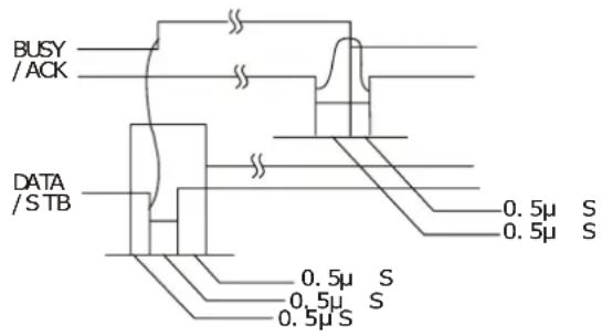
Fig 5-1 Timing signal in parallel
5.2.2 Serial Interface (Optional)
EC80320 printer's serial interface is compatible with RS-232C protocol, supporting RTS/CTS and XON/XOFF handshaking protocol. The DB-25 connector and each pin's definitions are shown as below.

Fig 5-2: Sequence numbers of Serial connector
Table A-2 Pin assignments of the serial interface
| Pin number | Signal From Description | ||
| 2 RXD | Host Receive data from Host | ||
| 3 TXD | Printer Sent | control code | X-ON/X-OFF and data to the Host |
| 5 CTS | Printer “MARK” state means printer is too busy to receive data; “SPACE” means printer is ready for receiving data. | ||
| 7 | GND | — | Signal GND |
| 8 DTR | Printer Same as CTS | ||
Note: "From" means from the source the signal sending out. Signal level is EIA level.
The default setting in serial stands for 9600bps, 8 bits, parity check disabled and 1 stop bit. EC80320 printer can be connected to the standard RS-232C connector. When connecting with an IBM PC or compatible PC, the connecting picture is shown as figure 5-3. While connecting with a 25 pin PC, you can connect the cable as shown in Fig 5-4.

Printer 9-Pin connector
Host 9-Pin connector
Fig5-3 TP820 connecting with 9-Pin PC

Printer 9PIN connector
Host 25PIN connector
Fig5-4 TP820 connecting with 25-Pin PC
5.2.3 USB Interface
Full-speed USB interface of version 2.0.

Fig 5-5 USB interface
5.2.4 Drawer Connector
The drawer connector on the back of the printer uses the RJ-11 connector, which is shown below.

Fig5-6 Drawer connector
Table A-3: Drawer connector Pin assignments
| Pin number | Signal Direction | |
| 1 | Frame | GND |
| 2 | kick-out drive signal OUT | |
| 3 | Open/closed signal IN | |
| 4 | 24VDC | OUT |
| 5 | kick-out drive signal OUT | |
| 6 | Drawer kick-out Open/closed signal ground ≤slant 1A/24V | --- |
| Drive electricity ≤slant 1A/24V | ||
Note: Make sure the drawer meets the specification mentioned above, or we will not guarantee to keep the printer in good repair.
5.2.5 Power Supply Connector
The connector is used to connect the printer to the external power source. The power source is specified as 24V ± 10% and 2.5A. The connector on the printer is shown in Fig 5-7.

Fig 5-7 Power connector
5.2.6 Ethernet Connector

Fig 5-8 Ethernet connector
Chapter6 Troubleshooting and Maintenance
6.1 Maintenance
To prolong the printer's life, make sure that the printer is well away from heaters and other sources of extreme heat, and the surrounding area is clean, dry, and free of dust.
Cleaning paper case and thermal head periodically is the main task of maintaining the printer. We will talk with this problem in this section. It is noted that make sure to power off the printer before maintenance.
Clear printer:
Dirt and dust does the most damage to the printer. Clean the paper in the printer and accumulated dirt in the thermal head as well despite the outer case of the printer prevents greater part of dust from invading.
Clean printer case:
Remove the dirt in the printer case with clean, soft cloth, and take out the paper pieces with a nipper.
Attention: Be careful not to scratch the printer parts when cleaning.
Clean the printer periodically according to the prescription as follows.
Periodical cleaning: Once every 6 months or 300 work days
Cleaning tool: Dry cloth (Soft cloth if metal parts)
6.2 Error Message on the Control Panel
When the malfunction is occurred, the printer will be off-line and give an alarm through indicators. You can make out different malfunction through the Table A-4 shown below.
Table A-4: Error message on the control panel
| Error indicator | PAPER OUT indicator | Malfunction | Solution |
| Blink fast OFF | Cutter error Re-posit the cutter | ||
| ON OFF | Cover is open Close the | cover tightly | |
| OFF ON | Paper near end Load the | paper again | |
| ON ON | Paper out Load the paper | again | |
| Blink | OFF | Thermal head over hot | Recover automatically |
6.3 Cutter Jammed or Error
If the auto-cutter was jammed, open the upper cover and take out the paper. If the upper cover can not be opened and the cutter still can not return to the normal position after restarting the printer, pull out the small cover upper the auto-cutter so that the cutter can
come out. Rotate the white plastic gear by hand in the direction of arrow to make the cutter return to the normal position which is shown as figure 6-1.

Figure 6-1 Adjust the cutter by hand
Chapter 7 Control Commands
7.1 General
The commands EC80320 supplies are based on ESC/POS, and are compatible with TM-88III serials.
The format described as following:
| Command | Function | ||
| Format: | ASCII: | Indicates the ASCII equivalents | |
| Decimal: | Indicates the decimal equivalents | ||
| Hex: | Written in hexadecimal code | ||
Description:
Describe the function of the command
7.2. Explanation of Terms
| BEL | Beeper | ||
| Format: | ASCII: | BEL | |
| Decimal: | 7 | ||
| Hex: | 07 | ||
Description:
Actives the printer buzzer
| HT | Horizontal tab | ||
| Format: | ASCII: | HT | |
| Decimal: | 9 | ||
| Hex: | O9 | ||
Description:
Moves the print position to the next horizontal tab position
| LF | Print and line feed | ||
| Format: | ASCII: | LF | |
| Decimal: | 10 | ||
| Hex: | OA | ||
Description:
Prints the data in the print buffer and feeds one line based on the current line spacing.
| FF | Print and Feed to next black mark position | ||
| Format: | ASCII: | LF | |
| Decimal: | 12 | ||
| Hex: | OC | ||
Description:
Prints the data in the print buffer and feeds paper to the print starting position on the next black mark position when black mark takes effect.
DLE EOT n
Real-time status transmissio
| Format: | ASCII: | DLE | EOT | n |
| Decimal: | 16 | 4 | n | |
| Hex: | 10 | 04 | n | |
Description:
Transmit the selected printer status according to the specified parameter n, 1<=n<=4;
n=1: Transmit print status
n=2: Transmit off-line status
n=3: Transmit error status
n=4: Transmit paper roll sensor status
*Note: Only valid in serial interface.
ESC BEL n1 n2
Beep for appointment
| Format: | ASCII: | ESC | BEL | n1 | n2 | n3 |
| Decimal: | 27 | 7 | n1 | n2 | n3 | |
| Hex: | 1B | 07 | n1 | n2 | n3 |
Description:
N1 specifies the length of beeping time, n2 specifies the length of intermission time and n3 is the beeping times. The unit of n1 and n2 is 100 milliseconds.
ESC SP
Set right-side character spacing
| Format: | ASCII: | ESC | SP | n |
| Decimal: | 27 | 32 | n | |
| Hex: | 1B | 20 | n |
Description:
Set the right-side spacing of the character to n^* (horizontal or vertical motion unit) n=0255 .
Horizontal or vertical motion unit is specified by GS P command
ESC !
Set print mode
| Format: | ASCII: | ESC | ! | n |
| Decimal: | 27 | 33 | n | |
| Hex: | 1B | 21 | n |
Description:
Select the print mode using n as follows. n=0\~255
| Bit | Value | Function |
| 0 | 0 | Character A |
| 1 | Character B | |
| 1, 2 | -- -- -- | Not define |
| 3 | 0 | Emphasize mode not selected |
| 1 | Emphasize mode selected | |
| 4 | 0 | Double-height not selected |
| 1 | Double-height selected | |
| 5 | 0 | Double-width not selected |
| 1 | Double-height selected | |
| 6 | -- -- -- | Not define |
| 7 | 0 | Underline mode not selected |
| 1 | Underline mode selected |
ESC \$
Set absolute print position
| Format: ASCII: ESC $ nL nH | ||||
| Decimal: 27 36 nL nH | ||||
| Hex: 1B 24 nL nH |
Description:
Set the distance from the beginning of the line to the position at which subsequent characters are to be printed.
The distance is (nL+nH^256)^ (horizontal or vertical motion unit). NI, nH=0\~255.
Horizontal or vertical motion unit are specified by GS P command.
ESC %
Selected/cancel user-define characters set
| Format: | ASCII: | ESC | % | n |
| Decimal: | 27 | 37 | n | |
| Hex: | 1B | 25 | n |
Description:
n=1, Select the user-define characters; n=0, Select inter characters.
Default: n=0
ESC &
Define user-define characters
| Format: | ASCII: | ESC & y | c1 | c2 | [x1 d1..d(y*x1)] | [xk d1..d(y*xk)] |
| Decimal: | 27 | 38 y | c1 | c2 | [x1 d1..d(y*x1)] | |
| Hex: | 1B | 26 y | c1 | c2 | [x1 d1..d(y*x1)] |
Description:
Define the user-define Characters from c1 to c2.
$$ y = 3; 3 2 < = c 1 < = c 2 < = 1 2 6; $$
$$ 0 < = x < = 1 2; [ \text { Character A } 1 2 ^ {} 2 4 ], 0 < = x < = 9; [ \text { Character B } 8 ^ {} 1 6 ]; $$
$$ d = 0 \sim 2 5 5; k = c 2 - c 1 + 1; $$
y specifies the number of bytes in the vertical direction, x specifies the number of dots in the horizontal direction, d specifies the user-define data.
ESC *
Select bit-image mode
| Format: | ASCII: | ESC * | m | n1 | n2 | d1..dk | |
| Decimal: | 27 | 42 | m | n1 | n2 | d1..dk | |
| Hex: | 1B | 2A | m | n1 | n2 | d1..dk | |
Description:
Select the image mode with m; n1 and n2 specify the number of dots. The image data d1...dk m=0,1,32,33; n1=0\~255; n2=0\~3; d=0\~255.
$$ k = n 1 + 2 5 6 \times n 2 (m = 0, 1) $$
$$ k = (n 1 + 2 5 6 \times n 2) \times 3 (m = 3 2, 3 3) $$
The number of dots in horizontal direction is n1+256×n2.
If the number dots exceed the max dot number in a line (shown as below), the excess data is ignored.
| m | Mode | Vertical direction | Horizontal direction | ||
| Number of dots | Dot density | Dot density | Number of dots(max) | ||
| 0 | 8-dot single-density | 8 | 68DPI | 101DPI | 288 |
| 1 | 8-dot double-density | 8 | 68DPI | 203DPI | 576 |
| 32 | 24-dot single-density | 24 | 203DPI | 101DPI | 288 |
| 33 | 24-dot double-density | 24 | 203DPI | 203DPI | 576 |
| ESC - | Turn underline mode on/off | ||||
| Format: | ASCII: | ESC | - | n | |
| Decimal: | 27 | 45 | n | ||
| Hex: | 1B | 2D | n | ||
| Description: | |||||
| n=0, 48 | Turn underline mode off. | ||||
| n=1, 49 | one-dot thick underline mode on | ||||
| n=2, 50 | two-dot thick underline mode on | ||||
| ESC 2 | Set default line spacing | |||
| Format: | ASCII: | ESC | 2 | |
| Decimal: | 27 | 50 | ||
| Hex: | 1B | 32 | ||
Description:
Set the line spacing to 1/6 inch.
| ESC 3 | Set line spacing as n/203 inch | ||||
| Format: | ASCII: | ESC | 3 | n | |
| Decimal: | 27 | 51 | n | ||
| Hex: | 1B | 33 | n | ||
Description:
Set the line spacing to n^* (vertical or horizontal motion unit) n=0255 .
The vertical or horizontal motion units are specified by GS P Command.
| ESC = Select peripheral device | ||||
| Format: | ASCII: | ESC = n | ||
| Decimal: | 27 | 61 | n | |
| Hex: | 1B | 3D | n | |
Description:
The Last bit of n is 0, printer disable.
The Last bit of n is 1, printer enable.
| ESC ? | Cancel user-define character | ||||
| Format: | ASCII: | ESC | ? | n | |
| Decimal: | 27 | 63 | n | ||
| Hex: | 1B | 3F | n | ||
Description:
Cancel the character specified by n. n=32\~126.
| ESC @ | Initialize printer | |||
| Format: | ASCII: | ESC | @ | |
| Decimal: | 27 | 64 | ||
| Hex: | 1 B | 4 0 | ||
Description:
Initialize the printer to the state when the printer was turn on.
ESC D
Set horizontal tab position.
| Format: | ASCII: | ESC | D | n1......nk | NUL |
| Decimal: | 27 | 68 | n1......nk | NUL | |
| Hex: | 1B | 44 | n1......nk | NUL |
Description:
Set the horizontal tab position to the column specified by nk from the beginning of the line. n = 0\~255; k=0\~32;
ESC E
Turn emphasized mode on/off
| Format: | ASCII: | ESC | E | n |
| Decimal: | 27 | 69 | n | |
| Hex: | 1 B | 4 5 | n |
Description:
When the last bit (LSB) of the n is 0, the emphasized mode is turned off. When LSB of the n is 1, the emphasized mode is turned on.
ESC J
Print and feed paper
| Format: | ASCII: | ESC | J | n |
| Decimal: | 27 | 74 | n | |
| Hex: | 1B | 4A | n |
Description:
Prints the data in print buffer and feed the paper n*(horizontal or vertical motion unit) inches. n=0\~255; Horizontal or vertical motion unit are specified by GS P command.
ESC M
Select character font
| Format: | ASCII: | ESC | M | n |
| Decimal: | 27 | 77 | n | |
| Hex: | 1B | 4D | n |
Description:
n = 0,48; Character A (12*24) is selected; n = 1,49; Character B (8*16) is selected.
ESC R
Select the international character set
| Format: | ASCII: | ESC | R | n |
| Decimal: | 27 | 82 | n | |
| Hex: | 1B | 52 | n |
Description:
Selects the international character set according the value of n as shown in the follow.
0: USA 1: France 2: Germany 3: U.K 4: Denmark I 5: Sweden 6: Italy 7: Spain I 8: Japan 9: Norway 10: Denmark II 11: Spain II 12: Latin America 13: Korea
ESC V
Turn 90°clockwise rotation mode on/off
| Format: | ASCII: | ESC | V | n | |
| Decimal: | 27 | 86 | n | ||
| Hex: | 1B | 56 | n |
Description:
n=0,48 Turn off 90°clockwise rotation mode.
n=1,49 Turn on 90°clockwise rotation mode.
No 90°clockwise rotation for underline in underline mode.
ESC \
Set relative print position
| Format: | ASCII: | ESC | \ | nL | nH |
| Decimal: | 27 | 92 | nL | nH | |
| Hex: | 1B | 5C | nL | nH |
Description:
Set the print position at (nL+nH256)^ (horizontal or vertical motion unit) inches from current position;
nL,nH=0\~255. Horizontal or vertical motion unit is specified by GS P command.
ES C a n
Select justification
| Format: | ASCII: | ESC | a | n |
| Decimal: | 27 | 97 | n | |
| Hex: | 1 B | 6 1 | n |
Description:
n=0, 48: Left justification; n=1, 49: centering; n=2, 50; right justification.
ESC c 3
Select paper end sensor
| Format: | ASCII: | ESC | c | 3 | n | |
| Decimal: | 27 | 99 | 51 | n | ||
| Hex: | 1B | 63 | 33 | n |
Description:
n=xxxxxxxx1B, xxxxxx1xB, xxxxxx11B, Paper near end sensor takes effect.
n=xxxxx1xxB, xxxx1xxxB, xxxx11xxB, Paper end sensor takes effect.
ESC c 4
Select paper sensor to stop printing
| Format: | ASCII: | ESC | c | 4 | n | |
| Decimal: | 27 | 99 | 52 | n | ||
| Hex: | 1B | 63 | 34 | n | ||
Description:
n=xxxxxxxx1B, xxxxxx1xB, xxxxxx11B; Paper near end, printer stop printing.
n=xxxxx1xxB, xxxx1xxxB, xxxx11xxB; Paper end, printer stops printing.
ESC c 5
Enable/disable panel button
| Format: | ASCII: | ESC | c | 5 | n | |
| Decimal: | 27 | 99 | 53 | n | ||
| Hex: | 1B | 63 | 35 | n |
Description:
When the LSB of n is 0, enable button.
When the LSB of n is 1, disable button.
ESC d
Print and feed n lines
| Format: | ASCII: | ESC | c | n |
| Decimal: | 27 | 100 | n | |
| Hex: | 1B | 64 | n |
Description:
Print the data in print buffer and feed n lines, n=0\~255.
ESC j
Print and feed paper conversely
| Format: | ASCII: | ESC | j | n |
| Decimal: | 27 | 106 | n | |
| Hex: | 1B | 6A | n | |
Description:
Print the content in the buffer and feed paper n*vertical unit inch conversely.
n=0\~255. Horizontal or vertical motion unit is specified by GS P command.
Note: This function is only for Micro-adjustment. If the distance the paper feeding is over long, which may cause the paper jammed or deviating from print roller.
ESC p m t1 t2
Generate pulse
| Format: | ASCII: | ESC | p | m | t1 | t2 | ||
| Decimal: | 27 | 112 | m | t1 | t2 | |||
| Hex: | 1B | 70 | m | t1 | t2 | |||
Description:
Printer output pulse, whose width specified by t1 and t2. On time is t1*2ms, low ist2*2ms. m=0,48,1,49。
ESC t
Select code page
| Format: | ASCII: | ESC | t | n | |
| Decimal: | 27 | 116 | n | ||
| Hex: | 1B | 74 | n |
Description:
Selects a code page through n as follows:
n=0 PC437;n=1 PC437;n=2 PC850;n=3 PC860;n=4 PC863;
n=5 PC865;n=16 WPC1252;n=17 PC866;n=18 PC852;n=19 PC858;
ESC {
Turn on/off upside-down printing mode
| Format: | ASCII: | ESC | { | n |
| Decimal: | 27 | 123 | n | |
| Hex: | 1B | 7B | n |
Description:
When the LSB of n is 0, upside-down printing mode is turn off.
When the LSB of n is 1, upside-down printing mode is turn on.
FS!
Select Chinese character mode
| Format: ASCII: FS ! n | |||
| Decimal: 28 | 33 | n | |
| Hex: 1C | 21 | n | |
Description:
| Bit | Off/On | Hex | Decimal | Function |
| 0 | - | - | - | Not define |
| 1 | - | - | - | Not define |
| 2 | Off | 00 | 0 | Double-width is not selected |
| On | 04 | 4 | Double-width is selected | |
| 3 | Off | 00 | 0 | Double-height is not selected |
| On | 08 | 8 | Double-height is selected | |
| 4 | - | - | - | Not define |
| 5 | - | - | - | Not define |
| 6 | - | - | - | Not define |
| 7 | Off | 00 | 0 | Underline is selected |
| On | 80 | 128 | Underline is not selected |
Selects the Chinese character mode according n as follows:
FS &
Set Chinese language mode
| Format: | ASCII: | FS | & |
| Decimal: | 28 | 38 | |
| Hex: | 1C | 26 | |
Description:
In this mode, the code between 0x81 and 0xff are printed as Chinese character.
| FS - | Turn Chinese character underline mode on /off | |||
| Format: | ASCII: | FS | - | n |
| Decimal: | 28 | 45 | n | |
| Hex: | 1C | 2D | n | |
Description:
n=0, 48 turn off the Chinese character underline mode.
n=1, 49 turn one dot the thick underline of Chinese character mode on.
n=2, 50 turn two dots the thick underline of Chinese character mode on.
Underline mode is ignored if 90^ clockwise rotation is turned on at the same time.
| FS . | Cancel Chinese language mode | |||
| Format: | ASCII | FS | . | |
| Decimal: | 28 | 46 | ||
| Hex: | 1C | 2E | ||
Description:
In this mode No Chinese character printed.
FS 2
Define user-define Chinese characters
| Format: ASCII: | FS | 2 | c1 | c2 | d1......d72 |
| Decimal: | 28 | 50 | c1 | c2 | d1......d72 |
| Hex: | 1C | 32 | c1 | c2 | d1......d72 |
Description:
c1=fe; a1<=c2<=fe; 0<=d<=255; c1 specified the first byte of the character code, c2 specified the second byte of the character code. Data dk defined from up to down 3 bytes one column, and from left to right 24 columns.
FS S
Set Chinese character spacing
| Format: | ASCII: | FS | S | n1 | n2 | |
| Decimal: | 28 | 83 | n1 | n2 | ||
| Hex: | 1C | 53 | n1 | n2 | ||
Description:
0 ≤ n1 ≤ 255, 0 ≤ n2 ≤ 255 Set the character left-side spacing to n1^ (horizontal or vertical motion unit), right-side spacing to n2^ (horizontal or vertical motion unit).
Horizontal or vertical motion unit is specified by GS P command.
FS W
Turn quadruple-size mode on/off for Chinese character
| Format: | ASCII: | FS | W | n | |
| Decimal: | 28 | 87 | n | ||
| Hex: | 1C | 57 | n | ||
Description:
0 ≤ n ≤ 255
When the LSB of n is 0, turn off the quadruple-size mode.
When the LSB of n is 1, turn on the quadruple-size mode.
FS p n m
Print NV bit image
| Format: | ASCII: | FS | p | n | m |
| Decimal: | 28 | 112 | n | m | |
| Hex: | 1C | 70 | n | m |
Description:
1 ≤ n ≤ 64 m=0, 1, 2, 3, 48, 49, 50, 51
Prints the NV bit image n using the mode specified by m.
m = 0, 48 Normal mode; m = 1, 49 Double width mode;
m = 2, 50 Double height mode; m = 3, 51 Quadruple mode.
FS q n
Define the NV bit image
| Format: | ASCII: | FS | q | n | [xL xH yL yH d1 d2 ...dk]1...[xL xH yL yH d1 d2 ...dk] |
| Decimal: | 28 | 113 | n | [xL xH yL yH d1 d2 ...dk]1...[xL xH yL yH d1 d2 ...dk] | |
| Hex: | 1C | 70 | n | [xL xH yL yH d1 d2 ...dk]1...[xL xH yL yH d1 d2 ...dk] |
Description:
1 ≤ n ≤ 64; xH = 0; 0 <= xL <= 72; yH = 0; 0 <= yL <= 30
k=(xL+xH^256)^(yL+yH^256)^8
The command can define 64 bit images at the same time. All NV images preciously defined are canceled when new bit image defined. When this command processing, ERROR indicator will be on for a period time, then the PAPER OUT indicator and ERROR indicator will be both on and the printer resets. No more other data or commands followed this command, or may cause data lost or printing mess. The NV image data will be stored in the printer even which is powered off, and will not lose till this command reprocessed. Excessive use of this function may cause the NV memory damaged. As a guideline, the command should not be processed more than 10 times per day.
The hole command including the bit image data should less than 128K bytes (1M bits). xL,xL specifies (xL+xH*256) bytes in the horizontal direction for the NV bit image you defined. yL,yH specifies (yL+yH*256) bytes in the vertical direction for the NV bit image you defined. d specifies the definition data for the NV bit image(column format).
GS BEL n1 n2
Beep for appointment
| Format: | ASCII: | GS | BEL | n1 | n2 | n3 |
| Decimal: | 29 | 7 | n1 | n2 | n3 | |
| Hex: | 1D: | 07 | n1 | n2 | n3 |
Description:
N1 specifies the beeping times, n2 specifies the length of beeping time and n3 specifies the length of intermission time. The unit of n1, n2 is 0.1 second.
GS FF
Print and feed to next black mark position
| Format: | ASCII: | GS | FF |
| Decimal: | 29 | 12 | |
| Hex: | 1D | OC |
Description:
Print the content in the buffer and feed paper to the next black mark position.
GS !
Select Character size
| Format: | ASCII: | GS | ! | n |
| Decimal: | 29 | 33 | n | |
| Hex: | 1D | 21 | n | |
Description:
n=0\~7, 16\~23, 32\~39, 48\~55,64\~71,80\~87,96\~103,112\~119;
Selects the character height (vertical number of times normal font size) using bits0 to bits3 and selects the character width (horizontal number of times normal size) using bits4 to bits7.
GS ( F pL pH a m nL nH
Set adjustment
| Format: ASCII: | GS ( F pL pH a m nL nH | |||||||
| Decimal: 29 | 40 | 70 | pL | pH | a m | nL | nH | |
| Hex: | 1D | 28 | 46 | pL | pH | a m | nL | nH |
Description:
(pL+(pH×256))=4 (Here pL=4,pH=0); 1≤ a≤2 ; m=0,48 or 1,49
0 ≤ (nL + nH × 256) ≤ 65535 , (Here 0 ≤ nL ≤ 255, 0 ≤ nH ≤ 255 )
This command is only effective when allowing black mark sensor.
Set the printer adjustment value specified by a.
- The numbers of parameter (such as a) specified by pL and pH are (pL+ (pH*256)) bytes.
● A specifies the value of original position and paper cut position.
| a | Function |
| 1 | Set the value of original position |
| 2 | Set the value of paper cut position |
● M specifies the direction of adjustment.
| m | Function |
| 0, 48 | Specify the direction of feeding paper forward. |
| 1, 49 | Specify the direction of feeding paper conversely |
- The setting value of nL and nH is specified as (nL+nH*256)*0.125 millimeter.
| GS * | Define downloaded bit image | ||||||
| Format: | ASCII: | GS | * | n1 | n2 | d1...dk | |
| Decimal: | 29 | 42 | n1 | n2 | d1...dk | ||
| Hex: | 1D | 2A | n1 | n2 | d1...dk | ||
Description:
Define the downloaded bit image in the downloaded graphic area.
n1=1\~48, n2=1\~255, n1×n2<1200,k=n1×n2×8。
d specifies the bit image data . n1×8 dots in the horizontal direction and n2×8 dots in the vertical direction.
The downloaded bit image is available till printer is powered off or reset.
The format of bit image is shown below.

GS /
Print downloaded bit image
| Format: | ASCII: | GS | / | n | |
| Decimal: | 29 | 47 | n | ||
| Hex: | 1D | 2F | n |
Description:
Print the downloaded bit image using the mode specified by n. n=0, 1, 2, 3, 48, 49, 50, 51.
The bit image defined by GS* command. n specifies the mode as follows:
| n | Mode | Density in vertical | Density in horizontal |
| 0, 48 | Normal | 203DPI | 203DPI |
| 1, 49 | Double-width | 203DPI | 101DPI |
| 2, 50 | Double-height | 101DPI | 203DPI |
| 3, 51 | Quadruple | 101DPI | 101DPI |
GS B
Turn white/black reverse mode on/off
| Format: | ASCII: | GS | B | n |
| Decimal: | 29 | 66 | n | |
| Hex: | 1D | 42 | n |
Description:
When the LSB of n is 0, turn the white/black reverse mode off.
When the LSB of n is 1, turn the white/black reverse mode on.
GS H
Select print position of HRI character
| Format: | ASCII: | GS | H | n |
| Decimal: | 29 | 72 | n | |
| Hex: | 1D | 48 | n |
Description:
Select the print position of Human Readable Interpretation (HRI) when printing a bar code, using n as follows: n=0, 48: NO HRI printing. n=1, 49: above the barcode. n=2, 50: below the barcode. n=3, 51: Both above and below.
G S L
Set left margin
Format: ASCII: GS L nL nH
Decimal: 29 76 nL nH
Hex: 1D 4C nL nH
Description:
Set the left margin to (nL+nH256)(horizontal or vertical motion unit) ; nL, nH=0\~255.
Horizontal or vertical motion unit is specified by GS P command.
G S P
Set horizontal or vertical motion unit
Set the horizontal and vertical unit to 1/x inch and 1/y inch.
When x or y=0, the default horizontal or vertical unit is selected.
GS V
Select cut mode and cut paper
Format: ASCII: GS V m (n)
Decimal: 29 86 m (n)
Hex: 1D 56 m (n)
Description: (There is only one cut mode can be selected if the cutter can only realize one cut type.)
m=0, 48; No n parameter, Executes a full cut.
m=1, 49; No n parameter, Executes a partial cut (with one point left in the middle).
m=6, n=0\~255;Feed paper to n*(horizontal or vertical motion unit) and executes a full cut.
m=66, n=0\~255;Feed paper to n*(horizontal or vertical motion unit) and executes a partial cut.
GS W
Set print area width
Format: ASCII: GS W nL nH
Decimal: 29 87 nL nH
Hex: 1D 57 nL nH
Description:
Set the print area width to (nL+nH256)^ (horizontal or vertical motion unit), nL, nH=0\~255.
Horizontal or vertical motion units are specified by GS P.
GS f
Select the HRI character font
| Format: | ASCII: | GS | h | n |
| Decimal: | 29 | 102 | n | |
| Hex: | 1 D | 6 6 | n |
Description:
Selects the HRI character when printing a bar code, using n as follows:
n=0,48; Selects character A (12*24)
n=1,49; Selects character B (8*16)
GS h
Set bar code height
| Format: | ASCII: | GS | h | n |
| Decimal: | 29 | 104 | n | |
| Hex: | 1 D | 68 | n |
Description:
Set the height of the bar code to n dots.
n=0\~255.
GS k
Print bar code
| Format: | ASCII: | GS | k | m | d1..dk | NUL |
| Decimal: | 29 | 107 | m | d1..dk | 0 | |
| Hex: | 1 D | 6 B | m | d 1 .. d k 0 0 | ||
| * | ASCII: | GS | k | m | n | d1..dn |
| Decimal: | 29 | 107 | m | n | d1..dn | |
| Hex: | 1 D | 6 B | m | n d 1 .. d n |
*when m>64
| m | Bar code type | Amount of data | The range of k | character | Character code |
| 0 | UPC-A | Fixed | 11<=k<=12 | 0~9 | 48<=d<=57 |
| 1 | UPC-E | Fixed | 11<=k<=12 | 0~9 | 48<=d<=57 |
| 2 | EAN13 | Fixed | 12<=k<=13 | 0~9 | 48<=d<=57 |
| 3 | EAN8 | Fixed | 7<=k<=8 | 0~9 | 48<=d<=57 |
| 4 | CODE39 | Can be changed | 1<=k | 0~9,A~Z,SP,,%,+,-,/*(stat, stop) | 48<=d<=57,48<=d<=57,d=32,36,37,43,45,46,47. d=42(stat, stop) |
| *65 | UPC-A | Fixed | 11<=n<=12 | 0~9 | 48<=d<=57 |
| *66 | UPC-E | Fixed | 11<=n<=12 | 0~9 | 48<=d<=57 |
| *67 | EAN13 | Fixed | 12<=n<=13 | 0~9 | 48<=d<=57 |
| *68 | EAN8 | Fixed | 7<=n<=8 | 0~9 | 48<=d<=57 |
| *69 | CODE39 | Can be changed | 1<=n<255 | 0~9,A~Z,SP,,%,+,-,/*(star, stop) | 48<=d<=57,48<=d<=57,d=32,36,37,43,45,46,47. d=42(stat character) |
| *70 | ITF | Can be changed | 1<=n<255(Even) | 0~9 | 48<=d<=57 |
| *71 | CODABAR | Can be changed | 1<=n<255 | 0~9,A~D,$,+,-,/: | 48≤d≤57,65≤d≤68,36,43,45,46,47,58 |
| *73 | CODE128 | Can be changed | 2<=n<255 | NUL~SP(7FH) | 0<=d<=127 |
GS v 0
Print raster bit image
| Format: ASCII: GS v 0 m xL xH yL yH d1...dk | ||||||
| Decimal: 29 118 48 m xL xH yL yH d1...dk | ||||||
| Hex: 1D 76 30 m xL xH yL yH d1...dk |
Description:
Print a raster bit image using the mode specified by m as follows.
m=0, 48: normal; m=1, 49: double width; m=2, 50: double height; m=3, 51: quadruple.
XL,xH,yL,yH=0\~255;
XL,xH specifies (xL+xH*256) bytes in horizontal direction for the bit image;
YL,yH specifies (yL+yH*256) dots in vertical direction for the image.
k=(xL+xH^256)^(yL+yH^*256) indicates the number of bit image data.
GS w
Set barcode width
| Format: | ASCII: | GS | w | n |
| Decimal: | 29 | 119 | n | |
| Hex: | 1D | 77 | n |
Description:
Set the horizontal size of barcode.
$$ 2 < = n < = 6. $$
Appendix Commands List
Here list the commands supported in the printer in alphabetical order.
| Control commands Functions Page | ||
| BEL | Beeper | 32 |
| HT | Horizontal tab | 32 |
| LF | Print and line feed | 32 |
| FF | Print and Feed paper to next black mark position | 32 |
| DLE EOT Real-time status transmission | 32 | |
| ESC BEL Beep for appointment | 33 | |
| ESC SP | Set right-side character spacing | 33 |
| ESC ! | Set print mode | 33 |
| ESC $ Set absolute print position 33 | ||
| ESC % Select/cancel user-defined character set 34 | ||
| ESC & | Define user-define characters | 34 |
| ESC * | Select bit-image mode | 34 |
| ESC - | Turn underline mode on/off | 34 |
| ESC 2 | Select default line spacing | 35 |
| ESC 3 | Set line spacing | 35 |
| ESC = | Select peripheral device | 35 |
| ESC ? | Cancel user-define character | 35 |
| ESC @ | Initialize printer | 35 |
| ESC D | Set horizontal tab position | 35 |
| ESC E | Turn emphasized mode on/off | 36 |
| ESC J | Print and feed paper | 36 |
| ESC M | Select character font | 36 |
| ESC R | Select the international character set | 36 |
| ESC V | Turn 90°clockwise rotation mode on/off | 36 |
| ESC \ | Set relative print position | 36 |
| ESC a | Select justification | 37 |
| ESC c 3 | Select paper end sensor | 37 |
| ESC c 4 | Select paper sensor to stop printing | 37 |
| ESC c 5 | Enable/disable panel button | 37 |
| ESC d | Print and feed n lines | 37 |
| ESC j | Print and feed paper conversely | 37 |
| ESC p | Generate pulse | 38 |
| ESC t | Select code page | 38 |
| ESC { | Turn on/off upside-down printing mode | 38 |
| FS ! | Select Chinese character mode | 38 |
| FS & | Set Chinese language mode | 39 |
| FS - | Turn Chinese character underline on /off | 39 |
| FS . | Cancel Chinese language mode | 39 |
| FS 2 | Define user-define Chinese characters | 39 |
| FS S | Set Chinese character spacing | 39 |
| FS W | Turn quadruple-size mode on/off for Chinese character | 40 |
| FS p n m | Print NV bit image | 40 |
| FS q n | Define the NV bit image | 40 |
| GS BEL | Beep for appointment | 40 |
| GS FF | Print and Feed paper to next black mark position | 41 |
| GS ! | Select Character size | 41 |
| GS * | Define downloaded bit image | 41 |
| GS / | Print downloaded bit image | 42 |
| GS B | Turn white/black reverse mode on/off | 42 |
| GS H | Select print position of HRI character | 42 |
| GS L | Set left margin | 42 |
| GS P | Set horizontal or vertical motion unit | 43 |
| GS V | Select cut mode and cut paper | 43 |
| GS W | Set print area width | 43 |
| GS f | Select the HRI character font | 43 |
| GS h | Set bar code height | 43 |
| GS k | Print bar code | 43 |
| GS v 0 | Print raster bit image | 44 |
| GS w | Set bar code width | 44 |
Manufacturer: EC Printer


- Table of contents
- The Guide......i
- Chapter 1 Introduction....1
- Chapter 2 Connecting Cables ....3
- Chapter 3 Base Control Panel Operations....19
- Chapter 4 Install and Replace the Roll Paper....22
- Chapter 5 Features....24
- Chapter6 Troubleshooting and Maintenance....29
- Chapter 7 Control Commands....31
- Appendix Commands List 44
- Chapter 1 Introduction
- Features
- Part Description
- Parts Identification
- Chapter 2 Connecting Cables
- Unpacking
- Unpack the Protect Materials
- Connecting to Your Computer or Other Equipment
- Connecting the Parallel Interface Cable
- Connecting the Serial Interface Cable (Optional)
- Connecting the USB Interface Cable
- Connecting the Drawer Cable
- Connecting the Ethernet Cable
- Connecting the Adapter
- Setup the Print Driver and Select the Cutter
- Auto-install way
- Hand operated installing way
- 1) The installing steps for Windows 2000/XP are as follows:
- 2) The installing steps for Windows 7 are as follows:
- Network Settings
- Connecting Printer
- Setting IP Address
- Run NetFinder Software
- Search printer
- Setting printer's IP address
- 1) Correlative description for IP address settings
- 2) Setting printer's IP address
- Installing Printer Network Driver
- Newly-install printer network driver
- Upgrade-install printer network driver (setting driver's network port)
- Chapter 3 Base Control Panel Operations
- Control Panel
- Indicator
- KEY
- Self-Printing
- HEX DUMP PRINTING
- Restoring Factory Printer Settings
- Setting Slip Stitch
- Online-aptitude Parameter Settings
- Note: The parameter settings shown in the "Device Property"
- Chapter 4 Install and Replace the Roll Paper
- Paper Installed Steps
- Note
- Chapter 5 Features
- Interface Features
- Parallel Interface
- Serial Interface (Optional)
- USB Interface
- Drawer Connector
- Power Supply Connector
- Ethernet Connector
- Chapter6 Troubleshooting and Maintenance
- Maintenance
- Clear printer:
- Clean printer case:
- Error Message on the Control Panel
- Cutter Jammed or Error
- Chapter 7 Control Commands
- General
- Explanation of Terms
- Description:
- Appendix Commands List
Brand : EC Line
Model : EC-80320
Category : Label printer