DR-1508P - Video recorder IDIS - Free user manual and instructions
Find the device manual for free DR-1508P IDIS in PDF.


| Product Type | Network Video Recorder (NVR) |
| Model | IDIS DR-1508P |
| Video Inputs | 8 IP channels |
| Video Outputs | 1 HDMI, 1 VGA |
| Display Resolution | Up to 1920x1200 |
| Recording Performance | Up to 240ips @ 8MP, 40Mbps throughput |
| Compression | H.264, H.265 |
| Recording Modes | Time-Lapse, Event, Pre-Event, Panic |
| Playback | 4ch Full HD synchronous playback; Time-lapse, Event log search |
| Storage | 1 internal SATA2 HDD bay (up to 4TB) |
| Data Export | USB HDD, USB stick |
| Network | Fast Ethernet (IP cameras) x8, Fast Ethernet (client) x1 |
| PoE | 8 ports, IEEE 802.3at class 4, total 50W (DR-1508P) / 70W (DR-1508P-A) |
| USB Ports | 2 x USB 2.0 (max 0.5W each, not for charging) |
| Dimensions (W x H x D) | 205mm x 44.5mm x 216.4mm (8.07" x 1.75" x 8.52") |
| Weight (with 4TB HDD) | 1.38 kg (3.04 lb) |
| Power Input | 100-240V~, 50/60Hz, output 56V~1.28A or 54V~1.67A (two adapter options) |
| Power Consumption | 69W max (with 1 HDD) |
| Operating Temperature | 0°C - 40°C (32°F - 104°F) |
| Operating Humidity | 0% - 90% |
| Operating System | Embedded Linux |
| Event Notification | Email (attach clip .cbf/.mp4), Callback, Push notification (IDIS Mobile), HTTP |
| Approvals | FCC (Class A), CE, KC |
| Cleaning Instructions | Unplug, use damp soft cloth; no liquid or aerosol cleaners. |
| Safety Precautions | Do not open; no user-serviceable parts; refer servicing to qualified personnel. |
| Spare Parts & Repairability | Use only manufacturer-specified parts; contact retailer for service. |
Frequently Asked Questions - DR-1508P IDIS
User questions about DR-1508P IDIS
0 question about this device. Answer the ones you know or ask your own.
Ask a new question about this device
Download the instructions for your Video recorder in PDF format for free! Find your manual DR-1508P - IDIS and take your electronic device back in hand. On this page are published all the documents necessary for the use of your device. DR-1508P by IDIS.
USER MANUAL DR-1508P IDIS
Network Video Recorder
Installation Manual
DR-1504P
DR-1504P-A
DR-1508P
DR-1508P-A
This manual contains basic instructions on installing and using DirectIP Network Video Recorder, an IDIS product. Users who are using this product for the first time, as well as users with experience using comparable products, must read this manual carefully before use and heed to the warnings and precautions contained herein while using the product. Safety warnings and precautions contained in this manual are intended to promote proper use of the product and thereby prevent accidents and property damage and must be followed at all times.
Once you have read this manual, keep it at an easily accessible location for future reference.

- The manufacturer will not be held responsible for any product damage resulting from the use of unauthorized parts and accessories or from the user's failure to comply with the instructions contained in this manual.
- It is recommended that first-time users of DirectIP Network Video Recorder and individuals who are not familiar with its use seek technical assistance from their retailer regarding product installation and use.
- If you need to disassemble the product for functionality expansion or repair purposes, you must contact your retailer and seek professional assistance.
- Both retailers and users should be aware that this product has been certified as being electromagnetically compatible for commercial use. If you have sold or purchased this product unintentionally, please replace with a consumer version.
Safety Precautions

CAUTION
RISK OF ELECTRIC SHOCK
DO NOT OPEN

CAUTION: TO REDUCE THE RISK OF ELECTRIC SHOCK,
DO NOT REMOVE COVER (OR BACK).
NO USER-SERVICEABLE PARTS INSIDE.
REFER SERVICING TO QUALIFIED SERVICE PERSONNEL.

The lightning flash with arrowhead symbol, within an equilateral triangle, is intended to alert the user to the presence of uninsulated "dangerous voltage" within the product's enclosure that may be of sufficient magnitude to constitute a risk of electric shock.

The exclamation point within an equilateral triangle is intended to alert the user to the presence of important operating and maintenance (servicing) instructions in the literature accompanying the appliance.
| Symbol | Publication Description | |
| IEC60417, No.5032 Alternating current | ||
| IEC60417, No.5031 Direct current |
Important Safeguards
1. Read Instructions
All the safety and operating instructions should be read before the appliance is operated.
2. Retain Instructions
The safety and operating instructions should be retained for future reference.
3. Cleaning
Unplug this equipment from the wall outlet before cleaning it. Do not use liquid aerosol cleaners. Use a damp soft cloth for cleaning.
4. Attachments
Never add any attachments and/or equipment without the approval of the manufacturer as such additions may result in the risk of fire, electric shock or other personal injury.
5. Water and/or Moisture
Do not use this equipment near water or in contact with water.
6. Ventilation
Place this equipment only in an upright position. This equipment has an open-frame Switching Mode Power Supply (SMPS), which can cause a fire or electric shock if anything is inserted through the ventilation holes on the side of the equipment.
7. Accessories
Do not place this equipment on an unstable cart, stand or table. The equipment may fall, causing serious injury to a child or adult, and serious damage to the equipment. Wall or shelf mounting should follow the manufacturer's instructions, and should use a mounting kit approved by the manufacturer.

This equipment and cart combination should be moved with care. Quick stops, excessive force, and uneven surfaces may cause the equipment and cart combination to overturn.
8. Power Sources
This equipment should be operated only from the type of power source indicated on the marking label. If you are not sure of the type of power, please consult your equipment dealer or local power company. This equipment should be remain readily operable.
9. Power Cords
Operator or installer must remove power and TNT connections before handling the equipment.
10. Lightning
For added protection for this equipment during a lightning storm, or when it is left unattended and unused for long periods of time, unplug it from the wall outlet and disconnect the antenna or cable system. This will prevent damage to the equipment due to lightning and power-line surges.
11. Overloading
Do not overload wall outlets and extension cords as this can result in the risk of fire or electric shock.
12. Objects and Liquids
Never push objects of any kind through openings of this equipment as they may touch dangerous voltage points or short out parts that could result in a fire or electric shock. Never spill liquid of any kind on the equipment.
13. Servicing
Do not attempt to service this equipment yourself. Refer all servicing to qualified service personnel.
14. Damage requiring Service
Unplug this equipment from the wall outlet and refer servicing to qualified service personnel under the following conditions:
A. When the power-supply cord or the plug has been damaged.
B. If liquid is spilled, or objects have fallen into the equipment.
C. If the equipment has been exposed to rain or water.
D. If the equipment does not operate normally by following the operating instructions, adjust only those controls that are covered by the operating instructions as an improper adjustment of other controls may result in damage and will often require extensive work by a qualified technician to restore the equipment to its normal operation.
E. If the equipment has been dropped, or the cabinet damaged.
F. When the equipment exhibits a distinct change in performance — this indicates a need for service.
15. Replacement Parts
When replacement parts are required, be sure the service technician has used replacement parts specified by the manufacturer or that have the same characteristics as the original part. Unauthorized substitutions may result in fire, electric shock or other hazards.
16. Safety Check
Upon completion of any service or repairs to this equipment, ask the service technician to perform safety checks to determine that the equipment is in proper operating condition.
17. Field Installation
This installation should be made by a qualified service person and should conform to all local codes.
18. Correct Batteries
Warning: Risk of explosion if battery is replaced by an incorrect type. Replace only with the same or equivalent type. Dispose of used batteries according to the instructions. The battery shall not be exposed to excessive heat such as sunshine, fire or the like.
19. Tmra
A manufacturer's maximum recommended ambient temperature (Tmra) for the equipment must be specified so that the customer and installer may determine a suitable maximum operating environment for the equipment.
20. Elevated Operating Ambient Temperature
If installed in a closed or multi-unit rack assembly, the operating ambient temperature of the rack environment may be greater than room ambient. Therefore, consideration should be given to installing the equipment in an environment compatible with the manufacturer's maximum rated ambient temperature (Tmra).
21. Reduced Air Flow
Installation of the equipment in the rack should be such that the amount of airflow required for safe operation of the equipment is not compromised.
22. Mechanical Loading
Mounting of the equipment in the rack should be such that a hazardous condition is not caused by uneven mechanical loading.
23. Circuit Overloading
Consideration should be given to connection of the equipment to supply circuit and the effect that overloading of circuits might have on over current protection and supply wiring. Appropriate consideration of equipment nameplate ratings should be used when addressing this concern.
24. Reliable Earthing (Grounding)
Reliable grounding of rack mounted equipment should be maintained. Particular attention should be given to supply connections other than direct connections to the branch circuit (e.g., use of power strips).
HDMI Port Precautions
- Use a certified cable marked with an HDMI logo when using HDMI. The screen may not display or a connection error may occur if you do not use a certified HDMI cable.
- It is recommended that you use the following HDMI cable type.
– High-speed HDMI Cable
– High-speed HDMI Cable with Ethernet
In-Text
Symbol Type Description


Caution Important information concerning a specific function.
Note Useful information concerning a specific function.
User's Caution Statement
Caution: Any changes or modifications to the equipment not expressly approved by the party responsible for compliance could void your authority to operate the equipment.
FCC Compliance Statement
THIS EQUIPMENT HAS BEEN TESTED AND FOUND TO COMPLY WITH THE LIMITS FOR A CLASS A DIGITAL DEVICE, PURSUANT TO PART 15 OF THE FCC RULES. THESE LIMITS ARE DESIGNED TO PROVIDE REASONABLE PROTECTION AGAINST HARMFUL INTERFERENCE WHEN THE EQUIPMENT IS OPERATED IN A COMMERCIAL ENVIRONMENT. THIS EQUIPMENT GENERATES, USES, AND CAN RADIATE RADIO FREQUENCY ENERGY AND IF NOT INSTALLED AND USED IN ACCORDANCE WITH THE INSTRUCTION MANUAL, MAY CAUSE HARMFUL INTERFERENCE TO RADIO COMMUNICATIONS. OPERATION OF THIS EQUIPMENT IN A RESIDENTIAL AREA IS LIKELY TO CAUSE HARMFUL INTERFERENCE, IN WHICH CASE USERS WILL BE REQUIRED TO CORRECT THE INTERFERENCE AT THEIR OWN EXPENSE.
WARNING: CHANGES OR MODIFICATIONS NOT EXPRESSLY APPROVED BY THE PARTY RESPONSIBLE FOR COMPLIANCE COULD VOID THE USER'S AUTHORITY TO OPERATE THE EQUIPMENT.
THIS CLASS OF DIGITAL APPARATUS MEETS ALL REQUIREMENTS OF THE CANADIAN INTERFERENCE CAUSING EQUIPMENT REGULATIONS.
WEEE (Waste Electrical & Electronic Equipment)
Correct Disposal of This Product
(Applicable in the European Union and other European countries with separate collection systems)
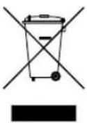
This marking shown on the product or its literature, indicates that it should not be disposed with other household wastes at the end of its working life. To prevent possible harm to the environment or human health from uncontrolled waste disposal, please separate this from other types of wastes and recycle it responsibly to promote the sustainable reuse of material resources.
Household users should contact either the retailer where they purchased this product, or their local government office, for details of where and how they can take this item for environmentally safe recycling.
Business users should contact their supplier and check the terms and conditions of the purchase contract. This product should not be mixed with other commercial wastes for disposal.
Copyright
© 2022 IDIS Co., Ltd.
IDIS Co., Ltd. reserves all rights concerning this manual.
Use or duplication of this manual in part or whole without the prior consent of IDIS Co., Ltd. is strictly prohibited.
Contents of this manual are subject to change without prior notice.
Registered Trademarks
IDIS is a registered trademark of IDIS Co., Ltd.
Other company and product names are registered trademarks of their respective owners.
The information in this manual is believed to be accurate as of the date of publication even though explanations of some functions may not be included. We are not responsible for any problems resulting from the use thereof. The information contained herein is subject to change without notice. Revisions or new editions to this publication may be issued to incorporate such changes.
The software included in this product contains some Open Sources. You may obtain the complete corresponding source code depending on whether or not the source is publicly available under a license policy. Go to System Setup - About page for more information. This product includes software developed by the University of California, Berkeley and its contributors, and software developed by the OpenSSL Project for use in the OpenSSL Toolkit (http://www.oepnssl.org/). Also, this product includes cryptographic software written by Eric Young (eay@cryptsoft.com), and software written by Tim Hudson (tjh@cryptsoft.com).
1
Part 1 – Introduction......7
Product Features ....7
Accessories....8
Overview 9
Front Panel....9
Dimensions....10
Rear Panel 11
Rear Panel Connections 12
2
Part 2 - Appendix....14
System Log Types ....14
Error Code Types ....15
Troubleshooting 18
Specifications 19
Product Features
This is a DirectIP-enabled video recorder that supports surveillance, recording, and playback of video from network cameras (or video encoders).
This NVR (Network Video Recorder) unit offers the following features:
• Real-time 4/8 channel DirectIP network surveillance
• Network camera zero configuration
- Configuration-free network camera access
• Supports up to 8MP 240ips video recording (DR-1508P)
• Supports up to 8MP 120ips video recording (DR-1504P)
• HDMI out (1) and VGA out (1) ports
- Fast and easy search feature (Time-Lapse, Event log)
- Simultaneously survey, record, play back, and transmit data in real-time
• Graphic User Interface(GUI) and multilingual
- Multiple recording modes (Schedule, Event, Pre-Event, and Panic)
- PoE-enabled Camera Connection
- 2 x USB 2.0 (for connecting peripherals, upgrading software, and saving recording data)
• 1 internal SATA2 HDD bay
- Self-diagnosis and automated system event alerts (industry standard S.M.A.R.T. protocol for HDD status alerts)
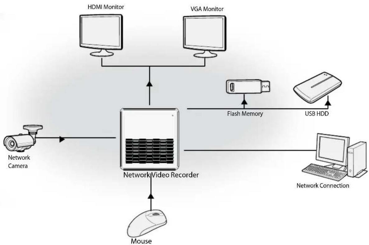
flowchart
graph TD
    A["Network Camera"] --> B["Network Video Recorder"]
    C["HDMI Monitor"] --> B
    D["VGA Monitor"] --> B
    B --> E["Mouse"]
    F["Flash Memory"] --> B
    G["USB HDD"] --> H["Computer"]
    I["Network Connection"] --> H
Accessories
Upon unpackaging the product, check the contents inside to ensure that all the following accessories are included.
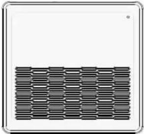 | 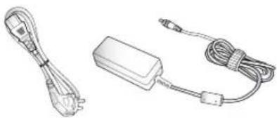 | 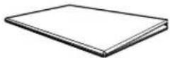 |
| Network Video Recorder | Power Cable / *DC Adapter *Above image may differ slightly from the actual product. | Quick Guide |
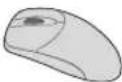 | ||
| Optical USB Mouse | ||
Overview
Front Panel
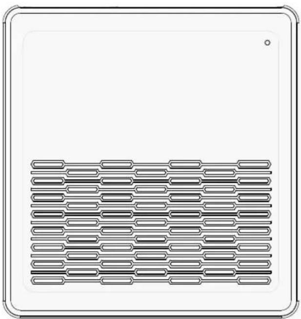
natural_image
Pure technical diagram of a rectangular panel with internal parallel slots and a central grid pattern (no text or symbols)LEDs
- HDD LED & Power LED: Lights up while the main unit is in operation and flashes when data is being written on the HDD or a video search is in progress.

- Access various windows and menus using a USB mouse as you would on a personal computer. - For easier system configuration, a USB mouse is recommended.
Dimensions
(Unit - mm)
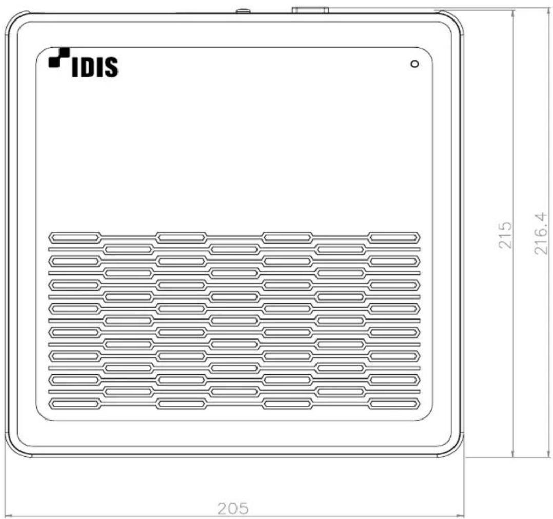
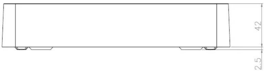

The IDIS logo should be positioned correctly when fixing the product to the wall.
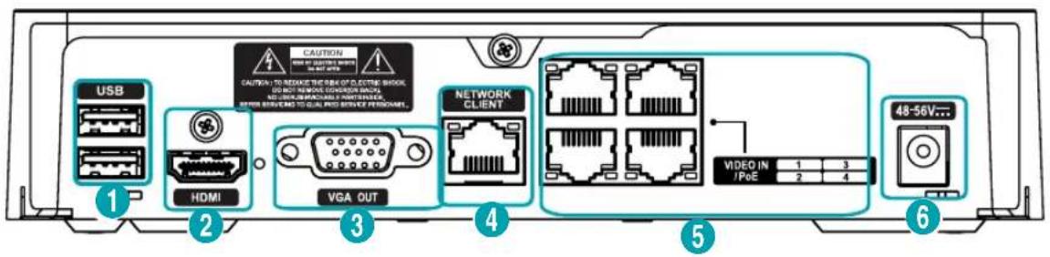
Rear Panel
DR-1504P
DR-1508P
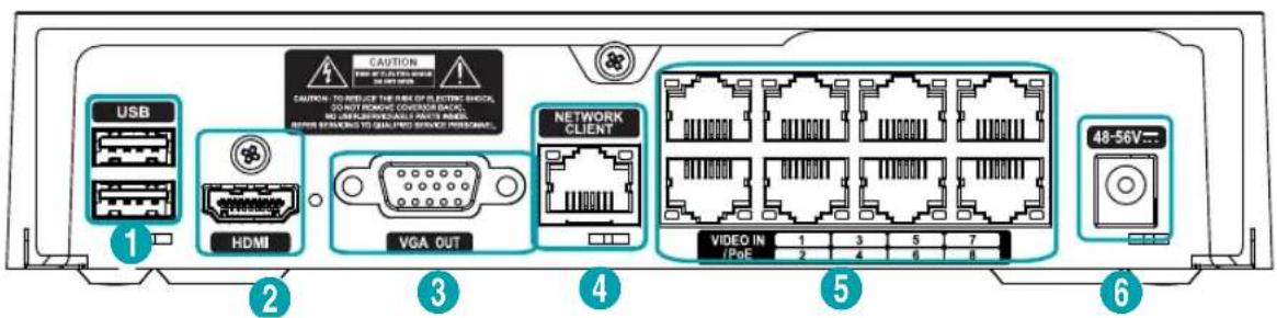
| 1 | USB Port | 2 | HDMI Out Port | 3 | VGA Out Port |
| 4 | Network Port | 5 | Video In / PoE Ports | 6 | Power In Port |
Part 1 – Introduction
Rear Panel Connections

For simplicity, the illustrations and descriptions in the rear panel connections refer to the DR-1308P model.
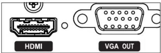
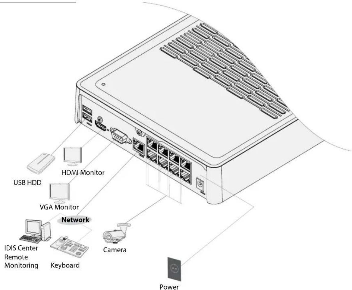
Monitor Connection
Connect to the VGA OUT or HDMI port.
Network Connection
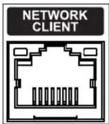
This NVR is capable of connecting to networks via an ethernet connector. Connect an RJ-45 cable (Cat5, Cat5e, or Cat6) to the NVR's network port. It's possible to operate and upgrade the NVR remotely over a network. Fore more information on ethernet connection setup, refer to Network Setup in the operation manual.

Green LED on the right will begin to turn on if connected a 100Mbps network. Orange LED on the left will then flash once a link has been established.
Video Connection
• Video In/PoE Port
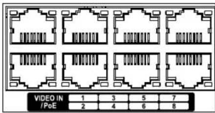
Connect network cameras or video encoders to the NVR using RJ-45 cable (Cat5, Cat5e, or Cat6). The NVR recognizes DirectIP network cameras automatically.

- Green LED on the right will turn on when PoE comes on line. Orange LED on the left will then flash once a link has been established.
Power Cable Connection
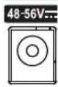
This NVR does not feature a separate power on/off button and will turn on the moment power is supplied. Connect the connector of adapter to the NVR and then connect the AC power cable of adapter to the power outlet.

- Organize the power cable so that it will not cause people to trip over or become damaged from chairs, cabinets, desks, and other objects in the vicinity. Do not run the power cable underneath a rug or carpet. - Do not connect multiple devices to a single power outlet.
Connections on the Rear Panel
System Log Types
| Boot Up Panic On | |
| System Shutdown Panic Off | |
| Restart Clear All Data | |
| Upgrade Success Clear Disk | |
| Upgrade Error Format Disk | |
| Power Failure Disk Full | |
| Time Changed Auto Deletion | |
| Time Zone Change Search Begin | |
| Time Sync. Search End | |
| Time Sync. Failed Clip-Copy Begin | |
| Disk Bad Clip-Copy End | |
| Login Clip-Copy Cancel | |
| Logout Clip-Copy Failure | |
| Setup Begin Clip Copy User | |
| Setup End Clip-Copy Begin | |
| Remote Setup Change Clip-Copy Finished | |
| Remote Setup Failure | Clip Copy Duration of Video |
| Setup Import | Clip Copy Camera |
| Setup Import Failure | Callback Failed |
| Setup Export Factory Reset | |
| Setup Export Failure | Camera Upgrade Begin |
| Setup Export Canceled | Camera Upgrade End |
| Schedule On | Camera Upgrade Failure |
| Schedule Off | Camera Upgrade User |
| Camera Upgrade Camera |
Error Code Types
| Upgrade Error Codes | |||
| No. Type | No. Type | ||
| 0 Unknown Error 301 Remote Network Error | |||
| 1 Incorrect File Version 302 No Remote Upgrade Permission | |||
| 2 Incorrect OS Version 303 Remote Upgrade File Save Failure | |||
| 3 Incorrect Software Version 304 Remote Upgrade Cancelled by User | |||
| 4 Incorrect Kernel Version 400 USB Storage Device Mount Failure | |||
| 100 Storage Device Mount Failure 401 USB Storage Device File Read Failure | |||
| 101 File Not Found 402 USB Storage Device File Copy Failure | |||
| 102 File Decompression Failure | 403 USB Device Not Connected | ||
| 103 LILO Execution Failure | 404 USB Storage Device in Use | ||
| 104 Reboot Failure 405 Unsupported File System | |||
| 105 Improper File | 500 Clip Copy in Progress: Upgrade Not Available | ||
| 300 Remote Connection Failure | |||
| Clip Copy Error Codes | |||
| No. Type No. Type | |||
| 0 Unknown Error 12 Disk Error | |||
| 1 Device Error 13 Clip Player Execution File Not Found | |||
| 2 Device Connection Failure 14 Clip Player Execution File Access | Failure | ||
| 3 CD Media Not Found 15 Clip Player Execution File Save Failure | |||
| 4 Incorrect Media 16 Image Generation Failure | |||
| 5 File Name Taken 17 Burn Failure | |||
| 6 Insufficient Space 18 Burn Time Overrun | |||
| 7 Temporary File Generation Failure 19 Device Connection Failure | |||
| 8 Disk Access Failure 20 Device in Use | |||
| 9 Disk Format Failure | 21 Unsupported File System | ||
| 10 Database Changed | 22 | Data Validation Failure | |
| 11 Save Failure | 23 No | Saved Data within Range | |
| Network Error Codes | |||
| No. Type | No. Type | ||
| 0 Cause of Failure Unknown 20 Connection Cancelled by User | |||
| 1 Normal Logout 21 No Response from Network Device Host | |||
| 2 All Channels in Use - Connection Denied 22 High Network Noise Level | |||
| 3 Incorrect Product Version Info 23 Transmission Queue Full | |||
| 4 Incorrect User Name or Password 24 Incorrect OEM Info | |||
| 5 Forced Disconnection by Admin 25 No Search Permission | |||
| 6 Timeout 26 Port in Use | |||
| 7 Network Device Terminated 27 SSL Connection Failure | |||
| 8 Unable to Connect: No Available Port 28 Network Timeout | |||
| 9 Server Not in Operation: Unable to Connect 29 Network Device Host Timeout | |||
| 11 Network Unavailable 30 | RTP via TCP Not Supported by Network Device Host | ||
| 12 Different Network Zone: Unable to Access 31 Socket Error | |||
| 13 Connection Timeout 100 Unknown CODEC | |||
| 14 Forced Disconnection by Network Device 101 .jpeg CODEC (not supported) | |||
| 15 Network Device Host Terminated 103 .mpeg4 CODEC (not supported) | |||
| 16 Unable to Route to Network Device Host 400 | Unsupported Resolution | ||
| 17 Connection Severed -1 Normal Access | |||
Troubleshooting
| Problem Solution | |
| The main unit won't turn on. | Check the power cable connection status.Check the power outlet. |
| Unable to display Live video. | Check the camera's video cable connection status.Check the monitor's video cable connection status.Check the camera's power setting.Check the camera lens settings. |
| PoE-enabled camera will not turn on. | Verify that the camera is actually PoE-enabled.Check the network cable, replace it, and try again.Check the PoE adapter is not defective and power adapter is properly connected. |
| NVR stopped working in the middle of a recording. | Hard disk may be full. Delete video recordings to free up space.Set the NVR to Recycle mode. For more information, refer to the General in the operation manual. |
| icon is shown, but video is not being recorded. | If the Pre-Event is enabled, the and icons appears when recording is not in progress, or the and icons appear when an event occurs and recording is in progress. For more information, refer to the Schedule in the operation manual. |
Specifications
These product specifications may change without prior notice.
| VIDEO | |
| Video Inputs 4 / 8 IP channels | |
| Video Outputs 1 HDMI, 1 VGA | |
| Display Resolution 1920 x 1200 , 1920 x 1080, 1680 x 1050, 1600 x 1200 | |
| Display Speed | Up to 120ips (DR-1504P)Up to 240 ips (DR-1508P) |
| RECORDING | |
| Max. Throughput | 40Mbps, 240ips @ 8MP (DR-1508P)20Mbps, 120ips @ 8MP (DR-1504P) |
| Compression H.264, H.265 | |
| Recording Mode Time-Lapse, | Event, Pre-Event, Panic |
| PLAYBACK | |
| Performance 4ch Full HD synchronous playback | |
| Search Mode Time-lapse, Event log |
| STORAGE | |
| HDD SATA x 1 (Up to 4TB capacity for each disk) | |
| Total Capacity | 4TB=4TB x 1 |
| Data Export Device USB HDD, USB Stick | |
| NETWORK | |
| Video in Connection | Fast Ethernet (IP Camera) x8 (DR-1508P)Fast Ethernet (IP Camera) x4 (DR-1504P) |
| Client Connection Fast Ethernet(Client) x1 | |
| Transmission Speed 20Mbps | / 50Mbps(BRP Mode) |
| Camera Power | PoE(IEEE 802.3at class 4) supported 8 ports, 50W (DR-1508P)PoE(IEEE 802.3at class 4) supported 8 ports, 70W (DR-1508P-A)PoE(IEEE 802.3at class 4) supported 4 ports, 30W (DR-1504P)PoE(IEEE 802.3at class 4) supported 4 ports, 35W (DR-1504P-A) |
| Event Notification | Email(attach clip (.cbf) .MP4), Callback to Remote S/W, Push notification (IDIS Mobile), HTTP |
| INTERFACE | |
| Audio In / Out - | |
| Internal Buzzer No | |
Part 2 - Appendix
| USB | * USB 2.0 x 2* USB port cannot be used for charging. (Max. 0.5W) |
| GENERAL | |
| Operating System Embedded | Linux |
| Unit Dimensions(W x H x D) | 205mm x 44.5mm x 216.4mm (8.07" x 1.75" x 8.52") |
| Unit Weight | DR-1508P: 1.38kg (3.04 lb) (3.5" 4TB HDD) / DR-1504P: 1.36kg (3.00 lb) (3.5" 4TB HDD) |
| Working Temperature 0°C - 40°C (32°F ~ 104°F) | |
| Operating Humidity 0% - 90% | |
| Power Input | DR-1508P (Check out two adapter specifications below)(Input: 100-240V~, 50/60Hz, 2A, Output: 56V~, 1.28A) (EA10682T)(Input: 100-240V~, 50/60Hz, 1.2A, Output: 54V~, 1.67A) (FSP090-AWAN3)DR-1508P-A (Check out two adapter specifications below)(Input: 100-240V~, 50/60Hz, 2.5A, Output: 54V~, 1.86A) (GM95-540186-D)(Input: 100-240V~, 50/60Hz, 2.5A, Output: 54V~, 2.33A) (GM152-5400233-D)DR-1504P (Check out two adapter specifications below)(Input: 100-240V~, 50/60Hz, 1.5A, Output: 48V~, 1.0A) (E048-1G480100M2)(Input: 100-240V~, 50/60Hz, 1.2A, Output: 48V~, 1.0A) (DSA-48PFA-48)DR-1504P-A (Check out two adapter specifications below)(Input: 100-240V~, 50/60Hz, 1.5A, Output: 48V~, 1.0A) (E048-1G480100M2)(Input: 100-240V~, 50/60Hz, 1.5A, Output: 48V~, 1.35A) (S065-1A480135M2) |
| ** Power Consumption | DR-1508P54-56V~, 1.28-1.24A, 69W MAXDR-1508P-A54V~, 1.65A,89W MAXDR-1504P48V~, 0.9A, 43W MAXDR-1504P-A48V~, 1A, 48W MAX |
| Approvals FCC, CE, KC | |
** When one HDD(4TB) is installed, the value above was measured.
IDIS®
IDIS Co., Ltd.
For more information, please visit at
www.idisglobal.com
- Network Video Recorder
- Safety Precautions
- CAUTION
- Important Safeguards
- Read Instructions
- Retain Instructions
- Cleaning
- Attachments
- Water and/or Moisture
- Ventilation
- Accessories
- Power Sources
- Power Cords
- Lightning
- Overloading
- Objects and Liquids
- Servicing
- Damage requiring Service
- Replacement Parts
- Safety Check
- Field Installation
- Correct Batteries
- Tmra
- Elevated Operating Ambient Temperature
- Reduced Air Flow
- Mechanical Loading
- Circuit Overloading
- Reliable Earthing (Grounding)
- HDMI Port Precautions
- In-Text
- Symbol Type Description
- User's Caution Statement
- FCC Compliance Statement
- WEEE (Waste Electrical & Electronic Equipment)
- Correct Disposal of This Product
- Copyright
- Registered Trademarks
- 1
- Part 1 – Introduction......7
- 2
- Part 2 - Appendix....14
- Product Features
- Accessories
- Overview
- Front Panel
- LEDs
- Dimensions
- Rear Panel
- Part 1 – Introduction
- Rear Panel Connections
- Monitor Connection
- Network Connection
- Video Connection
- • Video In/PoE Port
- Power Cable Connection
- Error Code Types
- Troubleshooting
- Specifications
- IDIS®
Brand : IDIS
Model : DR-1508P
Category : Video recorder