DS-IR-310D - Video recorder IDIS - Free user manual and instructions
Find the device manual for free DS-IR-310D IDIS in PDF.


| Product Type | Video Recorder (DVR/NVR) |
| Brand | IDIS |
| Model | DS-IR-310D |
| Dimensions (W x D x H) | 300 mm x 200 mm x 50 mm |
| Weight | 1.5 kg |
| Power Supply | DC 12V, 2A |
| Power Consumption | ≤ 15W |
| Video Inputs | 4 BNC (1.0 Vp-p, 75Ω) |
| Video Output | 1 BNC, 1 HDMI, 1 VGA |
| Audio Input / Output | 1 RCA input, 1 RCA output |
| Recording Resolution | 1080p (1920 x 1080) at 15 fps per channel |
| Compression Format | H.265+ / H.265 / H.264 |
| Internal Storage | 1 SATA HDD up to 2TB (not included) |
| Network Interface | 1 x RJ45 10/100 Mbps |
| Remote Access | IDIS Center, IDIS Mobile app, web browser |
| Motion Detection | Yes, per channel configurable |
| Backup Methods | USB, network, eSATA (if available) |
| Operating Temperature | 0°C to 40°C |
| Humidity | 10% to 90% non-condensing |
| Maintenance & Cleaning | Wipe with dry cloth; keep vents clear of dust |
| Safety | Use only supplied power adapter; do not expose to liquids |
| Spare Parts & Repairability | HDD, power adapter, fan (user-replaceable); contact IDIS support for other parts |
| Included Accessories | Power adapter, remote control, mounting kit, user manual |
Frequently Asked Questions - DS-IR-310D IDIS
User questions about DS-IR-310D IDIS
0 question about this device. Answer the ones you know or ask your own.
Ask a new question about this device
Download the instructions for your Video recorder in PDF format for free! Find your manual DS-IR-310D - IDIS and take your electronic device back in hand. On this page are published all the documents necessary for the use of your device. DS-IR-310D by IDIS.
USER MANUAL DS-IR-310D IDIS
Network Video Recorder
Installation Manual
IR-310
IR-310-A
IR-310D
IR-310D-A
This manual contains basic instructions on installing and using DirectIP™ Network Video Recorder, an IDIS product. Users who are using this product for the first time, as well as users with experience using comparable products, must read this manual carefully before use and heed to the warnings and precautions contained herein while using the product. Safety warnings and precautions contained in this manual are intended to promote proper use of the product and thereby prevent accidents and property damage and must be followed at all times.
Once you have read this manual, keep it at an easily accessible location for future reference.

- The manufacturer will not be held responsible for any product damage resulting from the use of unauthorized parts and accessories or from the user's failure to comply with the instructions contained in this manual.
- It is recommended that first-time users of DirectIP™ Network Video Recorder and individuals who are not familiar with its use seek technical assistance from their retailer regarding product installation and use.
- If you need to disassemble the product for functionality expansion or repair purposes, you must contact your retailer and seek professional assistance.
- Both retailers and users should be aware that this product has been certified as being electromagnetically compatible for commercial use. If you have sold or purchased this product unintentionally, please replace with a consumer version.
- This equipment has the PFC (Power Factor Correction) circuit. For stable operation, use a sign-wave output UPS with an AVR(Automatic Voltage Regulator).
Safety Precautions
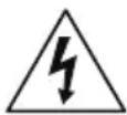
CAUTION
RISK OF ELECTRIC SHOCK DO NOT OPEN

CAUTION: TO REDUCE THE RISK OF ELECTRIC SHOCK, DO NOT REMOVE COVER (OR BACK). NO USER-SERVICEABLE PARTS INSIDE. REFER SERVICING TO QUALIFIED SERVICE PERSONNEL

The lightning flash with arrowhead symbol, within an equilateral triangle, is intended to alert the user to the presence of uninsulated "dangerous voltage" within the product's enclosure that may be of sufficient magnitude to constitute a risk of electric shock.

The exclamation point within an equilateral triangle is intended to alert the user to the presence of important operating and maintenance (servicing) instructions in the literature accompanying the appliance.
| Symbol | Publication Description | |
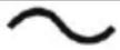 | IEC60417, No.5032 Alternating current | |
WARNING
Hazardous moving parts
Keep away from moving fan blades
AVERTISSEMENT
1. Read Instructions
All the safety and operating instructions should be read before the appliance is operated.
2. Retain Instructions
The safety and operating instructions should be retained for future reference.
3. Cleaning
Unplug this equipment from the wall outlet before cleaning it. Do not use liquid aerosol cleaners. Use a damp soft cloth for cleaning.
4. Attachments
Never add any attachments and/or equipment without the approval of the manufacturer as such additions may result in the risk of fire, electric shock or other personal injury.
5. Water and/or Moisture
Do not use this equipment near water or in contact with water.
6. Ventilation
Place this equipment only in an upright position. This equipment has an open-frame Switching Mode Power Supply (SMPS), which can cause a fire or electric shock if anything is inserted through the ventilation holes on the side of the equipment.
7. Accessories
Do not place this equipment on an unstable cart, stand or table. The equipment may fall, causing serious injury to a child or adult, and serious damage to the equipment. Wall or shelf mounting should follow the manufacturer's instructions, and should use a mounting kit approved by the manufacturer.
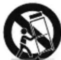
This equipment and cart combination should be moved with care. Quick stops, excessive force, and uneven surfaces may cause the equipment and cart combination to overturn.
8. Power Sources
This equipment should be operated only from the type of power source indicated on the marking label. If you are not sure of the type of power, please consult your equipment dealer or local power company. You may want to install a UPS (Uninterruptible Power Supply) system for safe operation in order to prevent damage caused by an unexpected power stoppage. Any questions concerning UPS, consult your UPS retailer.
This equipment should be remain readily operable.
9. Power Cords
Operator or installer must remove power and TNT connections before handling the equipment.
10. Lightning
For added protection for this equipment during a lightning storm, or when it is left unattended and unused for long periods of time, unplug it from the wall outlet and disconnect the antenna or cable system. This will prevent damage to the equipment due to lightning and power-line surges.
11. Overloading
Do not overload wall outlets and extension cords as this can result in the risk of fire or electric shock.
12. Objects and Liquids
Never push objects of any kind through openings of this equipment as they may touch dangerous voltage points or short out parts that could result in a fire or electric shock. Never spill liquid of any kind on the equipment.
13. Servicing
Do not attempt to service this equipment yourself. Refer all servicing to qualified service personnel.
14. Damage requiring Service
Unplug this equipment from the wall outlet and refer servicing to qualified service personnel under the following conditions:
A. When the power-supply cord or the plug has been damaged.
B. If liquid is spilled, or objects have fallen into the equipment.
C. If the equipment has been exposed to rain or water.
D. If the equipment does not operate normally by following the operating instructions, adjust only those controls that are covered by the operating instructions as an improper adjustment of other controls may result in damage and will often require extensive work by a qualified technician to restore the equipment to its normal operation.
E. If the equipment has been dropped, or the cabinet damaged.
F. When the equipment exhibits a distinct change in performance — this indicates a need for service.
15. Replacement Parts
When replacement parts are required, be sure the service technician has used replacement parts specified by the manufacturer or that have the same characteristics as the original part. Unauthorized substitutions may result in fire, electric shock or other hazards.
16. Safety Check
Upon completion of any service or repairs to this equipment, ask the service technician to perform safety checks to determine that the equipment is in proper operating condition.
17. Field Installation
This installation should be made by a qualified service person and should conform to all local codes.
18. Correct Batteries
Warning: Risk of explosion if battery is replaced by an incorrect type. Replace only with the same or equivalent type. Dispose of used batteries according to the instructions. The battery shall not be exposed to excessive heat such as sunshine, fire or the like.
A manufacturer's maximum recommended ambient temperature (Tmra) for the equipment must be specified so that the customer and installer may determine a suitable maximum operating environment for the equipment.
20. Elevated Operating Ambient Temperature
If installed in a closed or multi-unit rack assembly, the operating ambient temperature of the rack environment may be greater than room ambient. Therefore, consideration should be given to installing the equipment in an environment compatible with the manufacturer's maximum rated ambient temperature (Tmra).
21. Reduced Air Flow
Installation of the equipment in the rack should be such that the amount of airflow required for safe operation of the equipment is not compromised.
22. Mechanical Loading
Mounting of the equipment in the rack should be such that a hazardous condition is not caused by uneven mechanical loading.
23. Circuit Overloading
Consideration should be given to connection of the equipment to supply circuit and the effect that overloading of circuits might have on over current protection and supply wiring. Appropriate consideration of equipment nameplate ratings should be used when addressing this concern.
24. Reliable Earthing (Grounding)
Reliable grounding of rack mounted equipment should be maintained. Particular attention should be given to supply connections other than direct connections to the branch circuit (e.g., use of power strips).
HDMI Port Precautions
- Use a certified cable marked with an HDMI logo when using HDMI. The screen may not display or a connection error may occur if you do not use a certified HDMI cable.
- It is recommended that you use the following HDMI cable type.
-High-speed HDMI Cable
—High-speed HDMI Cable with Ethernet
In-Text
| Symbol | Type Description |
 | Caution Important information concerning a specific function. |
 | Note Useful information concerning a specific function. |
User's Caution Statement
Caution: Any changes or modifications to the equipment not expressly approved by the party responsible for compliance could void your authority to operate the equipment.
FCC Compliance Statement
THIS EQUIPMENT HAS BEEN TESTED AND FOUND TO COMPLY WITH THE LIMITS FOR A CLASS A DIGITAL DEVICE, PURSUANT TO PART 15 OF THE FCC RULES. THESE LIMITS ARE DESIGNED TO PROVIDE REASONABLE PROTECTION AGAINST HARMFUL INTERFERENCE WHEN THE EQUIPMENT IS OPERATED IN A COMMERCIAL ENVIRONMENT. THIS EQUIPMENT GENERATES, USES, AND CAN RADIATE RADIO FREQUENCY ENERGY AND IF NOT INSTALLED AND USED IN ACCORDANCE WITH THE INSTRUCTION MANUAL, MAY CAUSE HARMFUL INTERFERENCE TO RADIO COMMUNICATIONS. OPERATION OF THIS EQUIPMENT IN A RESIDENTIAL AREA IS LIKELY TO CAUSE HARMFUL INTERFERENCE, IN WHICH CASE USERS WILL BE REQUIRED TO CORRECT THE INTERFERENCE AT THEIR OWN EXPENSE.
WARNING: CHANGES OR MODIFICATIONS NOT EXPRESSLY APPROVED BY THE PARTY RESPONSIBLE FOR COMPLIANCE COULD VOID THE USER'S AUTHORITY TO OPERATE THE EQUIPMENT.
THIS CLASS OF DIGITAL APPARATUS MEETS ALL REQUIREMENTS OF THE CANADIAN INTERFERENCE CAUSING EQUIPMENT REGULATIONS.
WEEE (Waste Electrical & Electronic Equipment)
Correct Disposal of This Product
(Applicable in the European Union and other European countries with separate collection systems)
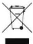
This marking shown on the product or its literature, indicates that it should not be disposed with other household wastes at the end of its working life. To prevent possible harm to the environment or human health from uncontrolled waste disposal, please separate this from other types of wastes and recycle it responsibly to promote the sustainable reuse of material resources.
Household users should contact either the retailer where they purchased this product, or their local government office, for details of where and how they can take this item for environmentally safe recycling.
Business users should contact their supplier and check the terms and conditions of the purchase contract. This product should not be mixed with other commercial wastes for disposal.
Copyright
© 2021 IDIS Co., Ltd.
IDIS Co., Ltd. reserves all rights concerning this manual.
Use or duplication of this manual in part or whole without the prior consent of IDIS Co., Ltd. is strictly prohibited.
Contents of this manual are subject to change without prior notice.
Registered Trademarks
IDIS is a registered trademark of IDIS Co., Ltd.
Other company and product names are registered trademarks of their respective owners.
The information in this manual is believed to be accurate as of the date of publication even though explanations of some functions may not be included. We are not responsible for any problems resulting from the use thereof. The information contained herein is subject to change without notice. Revisions or new editions to this publication may be issued to incorporate such changes.
The software included in this product contains some Open Sources. You may obtain the corresponding source code which we have to distribute according to the license policy. Go to Client Menu - About page for more information. This product includes software developed by the University of California, Berkeley and its contributors, and software developed by the OpenSSL Project for use in the OpenSSL Toolkit (http://www.openssl.org/). Also, this product includes cryptographic software written by Eric Young (eay@cryptsoft.com), and software written by Tim Hudson (tjh@cryptsoft.com).
Covered by one or more claims of the patents listed at patentlist.accessadvance.com.
1
Part 1 – Introduction....7
Product Features....7
Accessories....9
Overview 10
Front Panel....10
Dimensions....13
Rear Panel 14
Rear Panel Connections 15
2
Part 2 - RAID Configuration .... 18
Introduction 18
Getting Started....18
RAID and Disk Information 18
Event Log Viewer 20
Basic RAID Configuration 20
3
Part 3 - Recovery Solution User Guide ....2 2
4
Part 4 - Appendix ...... 2 3
Troubleshooting 23
Specifications 23
Product Features
This is a video recorder that supports surveillance, recording, and playback of video from network cameras (or video encoders).
This NVR (Network Video Recorder) unit offers the following features:
• UHD resolution support
• H.265 support codec
• 2 HDMI out ports
- 2 USB 2.0 port, 4 USB 3.0 port (for connecting peripherals, upgrading software, and saving recording data)
- 8 internal HotSpare SATA2 HDD bays and 3 eSATA ports
• Records the data efficiently (RAID 1,5,10)
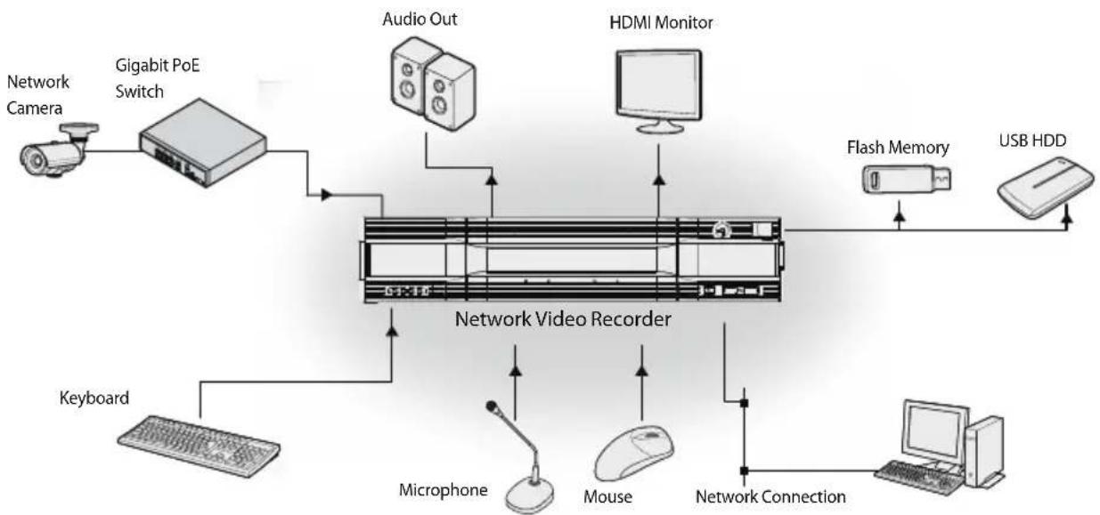
flowchart
graph TD
    A["Network Camera"] --> B["Gigabit PoE Switch"]
    B --> C["Audio Out"]
    C --> D["HDMI Monitor"]
    D --> E["Flash Memory"]
    E --> F["USB HDD"]
    G["Keyboard"] --> H["Microphone"]
    H --> I["Mouse"]
    I --> J["Network Connection"]
    K["Network Video Recorder"] --> L["Computer"]
Accessories
Upon unpackaging the product, check the contents inside to ensure that all the following accessories are included.
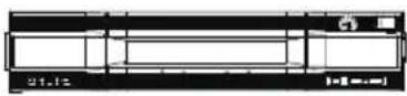 | 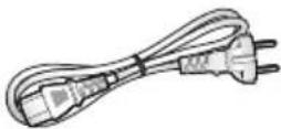 | 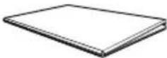 |
| Network Video Recorder Power | Cable Installation Manual | |
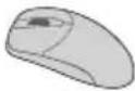 | 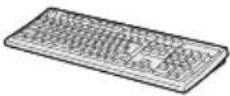 | |
| Optical USB Mouse Keyboard |

Please download IDIS Center software and product manual from this link:
- IDIS Website (www.idisglobal.com)
Front Panel
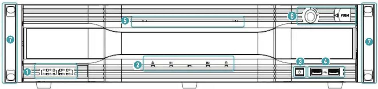
| 1 | SATA LED | 2 | Status LEDs | 3 | Power Button | 4 | USB Ports |
| 5 | Power LED | 6 | Front Door Lock | 7 | Rack Mount Ears |

• Some buttons have more than one function.
- Remote control sensor is located on the left side of the front panel. Ensure that the sensor remains unobstructed at all times. If obstructed, the sensor might not be able to receive remote control signals.
- Placing a Wi-Fi, Bluetooth, or any other wireless communication device near the NVR may interfere with remote control signal transmission.
- Access various windows and menus using a USB mouse as you would on a personal computer.
- For easier system configuration, a USB mouse and keyboard is recommended.
① SATA LED
These LEDs indicate the status of HDD and RAID mode.
| LED Color | HDD Status |
| On Green | SATA HDD Connection |
| Blinking Green | Data Transmission |
| Blinking Red | Rebuilding RAID SYSTEM |
| On Green/Red | HDD / RAID Error |
| Off | No SATA HDD |
② Status LEDs
Network LED: Lights up when the main unit is linked to an ethernet.
- R LED: LED works as the following table according to the RAID configuration.
| NON-RAID | Off |
| RAID 1 or RAID 10 | Blinking |
| RAID 5 | On |
- SSD LED: Lights up when the OS SSD is connected.
③ Power Button
Press to turn on the power of the NVR.
④ USB Ports
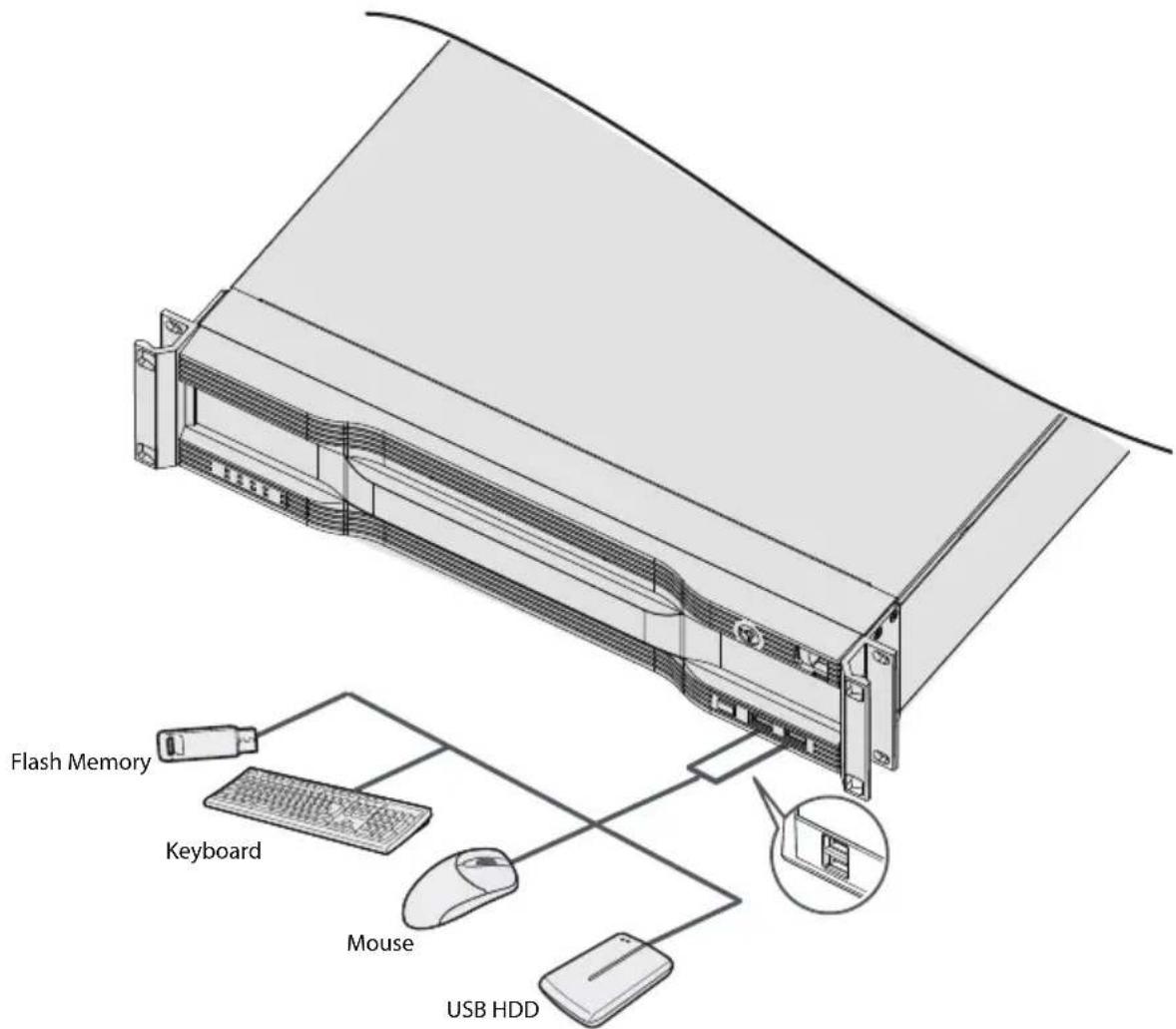
• Storage Device Connection
Connect an external USB hard drive or a USB flash memory device to one of the USB ports for use with the Clip Copy feature. The external storage device should be placed as close to the NVR as possible. It is recommended that you use a connection cable that is no longer than 180cm in length. Use the connection cable included with your external storage device to connect the device to one of NVR's USB ports. For more information on Clip Copy, refer to the Clip Copy in the operation manual.
• Peripheral Device Connection
Use the USB ports to connect peripherals such as a USB mouse and a keyboard to the NVR. You can also use a USB-to-serial converter and connect multiple text-in devices to the NVR at the same time.
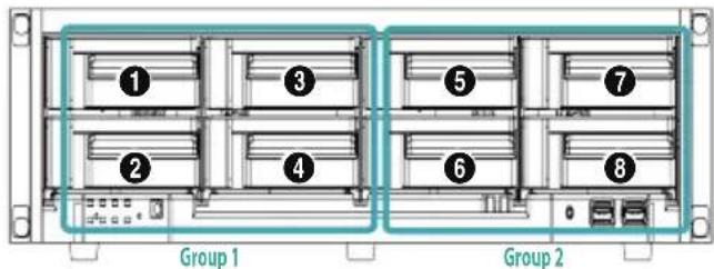
Port Number of HDD Drive
Refer to the following port number of HDD drive.
HDD Installation Precautions
Depending on the connection port, the HDDs are divided into two groups and they record video input individually as follows.
| Group 1 (1 ~ 4) | |
| HDD Port | Internal SATA Port 1, 2, 3, 4 |
| eSATA Port 1, 3 | |
⑤ Power LED
Lights up while the main unit is in operation.
⑥ Front Door Lock
By using enclosed door-lock key, front panel can be detachable to replace the HDD. For more information on how to replace the HDD, refer to the
Specifications on page 23.
⑦ Rack Mount Ears
The ears can be used for rack mount.

Rack Installation Precautions
- End users must install the rack according to the rack installation manual.
- You must use only the screws that are provided in the rack or only screws with dimensions mentioned in the rack installation manual.
- When installing this NVR in the rack, it must be installed by a skilled person or an instructed person.
| Group 2 (5 ~ 8) | |
| HDD Port | Internal SATA Port 5, 6, 7, 8 |
| eSATA Port 2, 4 | |

- To reuse the HDD which was used as a RAID, low-level format the drive. Otherwise, it is recognized as a RAID error and the data of all the connected HDDs may be deleted.
- Make sure to turn off the power before you add, remove or replace the HDD.
RAID Configuration Precautions
The four types of RAID configuration supported are as follows.
| Configuration 1 | *R1(1,2), R1(5,6) |
| HDD connection to Internal SATA Port 1,2,5,6 | |
| Configuration 2 | R1(1,2), R1(3,4), R1(5,6), R1(7,8) |
| After settingConfiguration 1, add HDD to Internal SATA Port 3,4,7,8 | |
| Configuration 3 | R5(1,2,3,4), R5(5,6,7,8) |
| Configuration 4 | R10(1,2,3,4), R10(5,6,7,8) |
* R1(1,2) means RAID 1, which is configured as the HDD connected to the Internal SATA port 1 and 2.
Connections on the Front Panel

- When configuring RAID, you must use HDDs with the same capacity of the same model.
- While RAID is rebuilding due to degradation, do not remove a HDD to configure the RAID. If you remove it, the data of all the connected HDDs may be deleted.
- It is recommended that you utilize Configuration 4, which is the most superior in seek speed and stability.
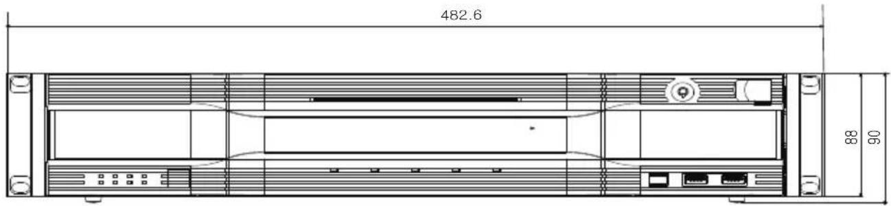
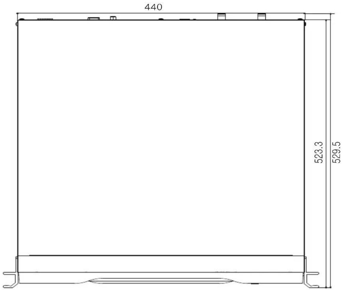
Dimensions
Unit: mm
Rear Panel
Single Power
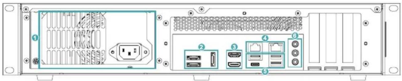
Dual Power (Redundant)
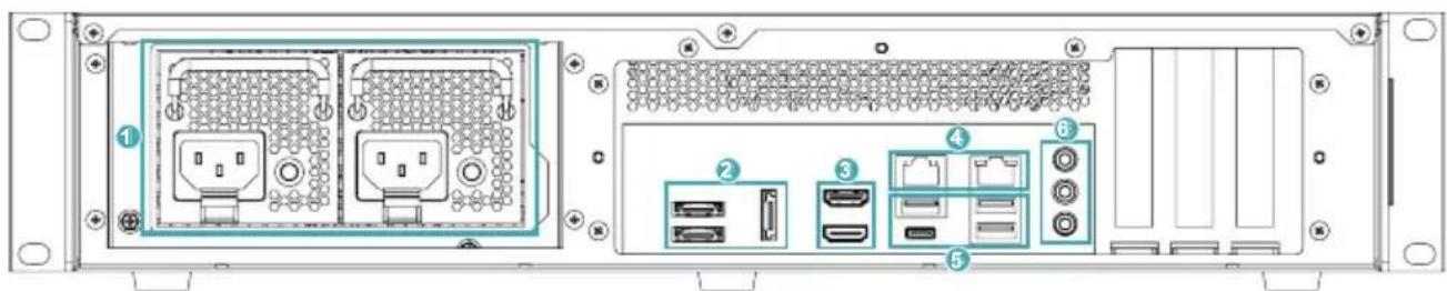
| 1 | Power In Port | 2 | eSATA Ports | 3 | HDMI Ports |
| 4 | Network Ports | 5 | USB Ports | 6 | Audio Connection |
The LED and Buzzer Control Rules of Redundant Power
| Condition | Power Module #1 Power Module #2 Buzzer | |||||
| AC Cord Included / Not Included | ||||||
| Power Module #1 | Power Module #2 | Green LED | Red LED Green LED | LED Red LED | ||
| Mounted Non-mounted | On Off | Off Blinking | On | |||
| Non-mounted Mounted | Off Blinking On Off | |||||
| Mounted | On Off | On Off | Off | |||
| Off | Blink when an warning event occurs | Off | Blink when an warning event occurs | Off | ||
| Off | On during a module failure | Off | On during a module failure | On | ||
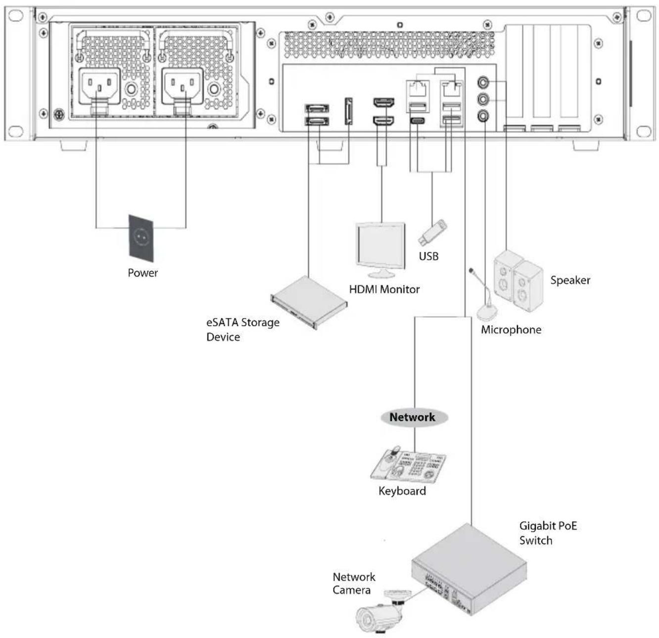
Rear Panel Connections

Installing a device other than the compatible list does not guarantee normal operation.
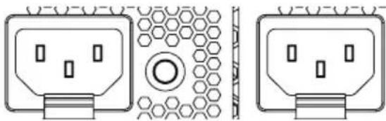
Power Cable Connection
Connect the power cable to this port. This NVR does not feature a separate power on/off button and will turn on the moment power is supplied.
Buzzer rings when a single power cable is connected, and you can turn off the buzzer by pressing the Power LED on the rear panel (2 power cable connection recommended).
natural_image
Technical line drawing of two electrical socket components with hexagonal patterns and mounting holes (no text or symbols)
- Organize the power cable so that it will not cause people to trip over or become damaged from chairs, cabinets, desks, and other objects in the vicinity. Do not run the power cable underneath a rug or carpet.
- The power cable is grounded. Do not modify the power plug even if your power outlet does not have a ground contact.
- Do not connect multiple devices to a single power outlet.
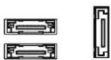
eSATA Connection
Connect external hard drives to these ports.

eSATA Compatibility List
Some eSATA storage device and configuration do not function properly except the following list.
| Model Company Note | ||
| IDS1004 IDIS | •Only the firmware version 0.966-1121is compatible.•Only the hard disk from the below list is compatible for the best performance. | |
Some hard disks may not function properly when mounted on to this product. Refer to the compatibility chart below before mounting any additional hard disk on to the product. Hard disk compatibility chart is subject to change without notice. Contact your retailer for the latest compatibility chart.
Storage Manufacturer Model
12TB TOSHIBA MG07ACA12TE

Do not connect or disconnect an eSATA device while the NVR is powered on. To connect an eSATA device, first turn off the NVR and unplug the power cable.
Connect the eSATA device and then power the eSATA device first and then NVR back on. To disconnect an eSATA device, first turn off the NVR and unplug the power cable. Turn off the eSATA device and then disconnect the eSATA connection cable.
Monitor Connection
Connect to the HDMI ports.
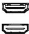

- Use a certified cable marked with an HDMI logo when using HDMI. The screen may not display or a connection error may occur if you do not use a certified HDMI cable.
- It is recommended that you use the following HDMI cable type.
-High-speed HDMI Cable
-High-speed HDMI Cable with Ethernet
RJ-45 Video/Network Connection
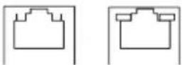
Connect network cameras or video encoders to the NVR using RJ-45 cable (Cat5, Cat5e, or Cat6). In addition to cameras or video encoders, you can connect external hubs (Optional: DH-2112PF, DH-2128PF, DH-2212PF) to form a network. The NVR recognizes DirectIP™ network cameras automatically.

- Green LED on the right will turn on if connected to a 1000 BASE-T network. Orange LED on the left will then flash once a link has been established.
This NVR is capable of connecting to networks via an ethernet connector. Connect an RJ-45 cable (Cat5, Cat5e, or Cat6) to the NVR's network port.

- Connector directions may vary depending on the NVR model.
- Green LED on the right will begin to flash if connected a 1000 BASE-T network. Orange LED on the left will then flash once a link has been established.
USB Port
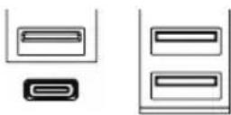
Support Super-speed USB 3.0 (5Gbps), High-Speed USB 3.0 (480Mbos) and Full Speed USB 2.0 (12Mbps) for transfer.
Audio Connection
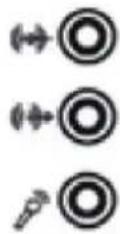
Connect the audio device to the AUDIO IN port and speakers with a built-in amplifier to the AUDIO OUT port.

- Check your local laws and regulations on making audio recordings.
Introduction
This chapter explains how to use JMB39X HW RAID Manager to configure RAID and monitor the status of the disks connected on JMB39X hardware RAID controller.
Once JMB39X HW RAID Manager is started, the JMB39X HW RAID Manager GUI window will be opened and the application icon could also be found in the notification tray located at the bottom right hand corner of the screen.
When the user presses the Basic Mode button on the right side of the GUI window, there are three buttons to be chosen for navigating the corresponding basic pages. Those basic pages are RAID and Disk Information page, Event Log Viewer page and Basic RAID Configuration page. Users could simply do basic RAID configuration and browse all disks and RAID information as well as the event logs in this basic mode.
Besides, there are some buttons appearing on the upper part of the GUI window and they are provided for users to minimize the window, close the window, turnoff the buzzer (if the buzzer exists) and open the About window.
Getting Started
RAID and Disk Information
The left part is a tree which shows all controllers on this platform and their connected RAID and disks in a hierarchy view. When the user selects a tree item, the detail information of the selected item will be displayed in the right part. All the disk and RAID information will be updated in real-time and users could monitor the status easily.
Controller Information
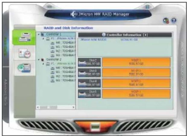
If the user selects a controller item from the tree view, it will display the model name and capacity of the RAID and disks connected on the specified controller at the right top table and also display all connected disk charts at the right bottom area. For RAID member disks, the disk charts will be drawn with the different colors according to the different RAID.
RAID Information
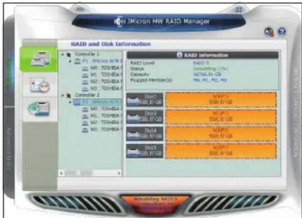
If the user selects a RAID item from the tree view, it will display the detail information of the specified RAID at the right top table and also display the RAID member disk charts at the right bottom area.
If the selected RAID is in rebuilding state, it will be highlighted with green color in the tree view. Also, the rebuilding animation will be played at the bottom left and right area. The rebuilding percentage is displayed at the bottom center area, too.
The user could simply click the RAID Information label to identify the member disks of the specified RAID with all disk LED flashings at the same time.
Disk Information
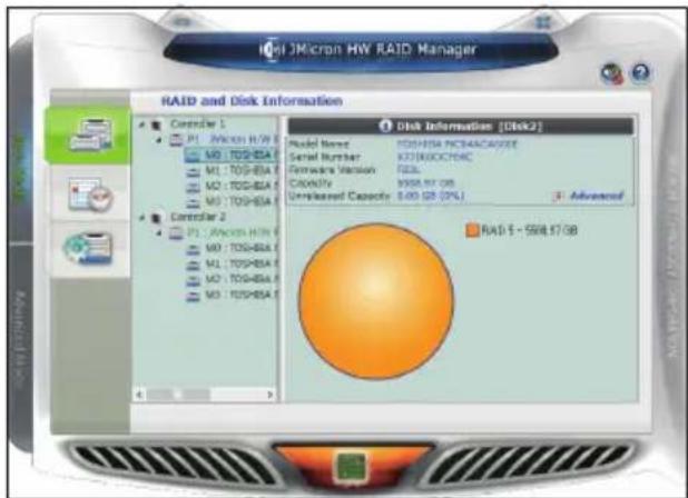
If the user selects a Disk item from the tree view, it will display the detail information of the specified disk at the right top table and also display the disk pie chart at the right bottom area.
If the selected disk is one member disk of the rebuilding RAID, the rebuilding animation will also be played at the bottom left and right area. The rebuilding percentage is displayed at the bottom center area, too.
The user could simply click the Disk Information label to identify the specified RAID with the disk LED flashing.
![Advanced Information SMART Information [TOSHIBA MCD4ACA60DE] ID Attribute Name Value Threshold Worst 1 Raw Read Error Rate 100 50 100 3 Spin up Time 100 1 100 4 Start/Stop Count 100 0 100 5 Reallocated sectors Count 100 30 100 7 Seek Error Rate 100 50 100 9 Power-On Hours 100 0 100 10 Spin Retry Count 106 30 100 OK](/content/2026/05/986721/images/0bcd21275620d5f74b3dac71e936846a60321e3f3f00421ba736f33cfbd33899.jpg)
If the disk is a RAID member disk, the application will show an Advanced... label at the right bottom corner of the table. The user could simply click it to browse the SMART information of the specified disk.
Event Log Viewer
JMicron HW RAID Manager will monitor the status of all connected disks and RAID and make records of the occurrence of the events. The user could browse all events through this event log viewer page.
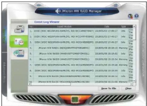
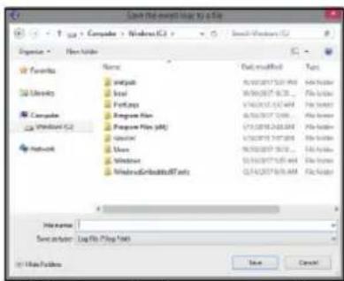
- Save to Profile: Save the logs to a profile. Enter the profile name when a dialog pops up.
• Clear: Clear all the logs.
Basic RAID Configuration
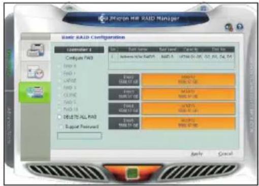
JMicron HW RAID Manager provides users to do the basic RAID configuration to the connected disk.
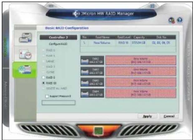
According to the number and capacity of the connected disks, JMicron HW RAID Manager will provide the available RAID type for users to select. When the user select his/her desired RAID type, JMicron HW RAID Manager will automatically select the available disks to build the RAID and calculate the RAID capacity. It will show the selected disks charts drawn in the cross pattern on the right.
Example) If the user selects RAID 10, JMicron HW RAID Manager will select four available disks to build RAID 10 starting from the lower Disk number. At the meanwhile, it will calculate the smallest disk size to build RAID and calculate the total capacity of the RAID.
After selecting the RAID type and setting the password (optional), the user just need press the Apply button to apply the configuration or press Cancel button to restore to the original disk state.
If the user wants to delete the existing RAID, the user could select the DELETE ALL RAID button to delete the RAID and apply it.
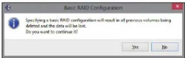
When the user presses the Apply button, it will pop up a dialog to ask for the confirmation.
![Information Information Message [Controller 2: 8] Micro H/W RAID10 (51Z90U4GZQHITW0J9Q3) is created. OK](/content/2026/05/986721/images/ae90a5a8ea017d88d902112e9d89b796107a1fb7ec183a1292101e5469a5f17a.jpg)
![Warning Warning Message [Controller 2: 6] Microcontroller RA1D10 [5129084GZQH32WQJ9QJ8] is deleted. OK](/content/2026/05/986721/images/474abb5bb6b94f88f9854287ea412f67409343cd03c392e1c90379cb44661455.jpg)
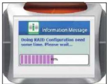
After the user confirms to apply the configuration, it will pop up another progress window to show the configuration status.
After the RAID configuration finishes, it will pop up a message dialog to tell that a RAID is newly created or a RAID has been deleted.
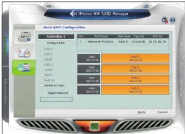
At last, the disk charts will be redrawn to reflect the result of the configuration. The newly created RAID will be shown with the gradient color. If the user deletes the RAID, the disk charts will be drawn in green color.
After the RAID configuration, restart the service from the IDIS Solution Suite Service Manager to properly apply the changed storage.
Part 3 - Recovery Solution User Guide
Entering the WinClon recovery area
1 Press the F11 key during boot.

Monitor display may be slow depending on monitor response speed. Therefore, it is recommended to press the F11 key immediately after the power is turned on. Entering the F11 key late may boot into Windows.
2 Press the F3 key or use the mouse to click on Restore to Initial State [F3]' in the center of the screen.
![WinClon 5 5.5.0.1 www.Clonie.co.kr Restore to Initial State [F5]](/content/2026/05/986721/images/54383795f6605c986926319c58d04b8710a471d3812b06ee25173b47862f10f7.jpg)
3 Enter the password. Factory default password is 0000.
4 When restoration is complete, click OK button on the completion message window. The system will automatically reboot into the restored environment.
Part 4 - Appendix
Troubleshooting
| Problem Solution | |
| The main unit won't turn on. | Check the power cable connection status.Check the power outlet.Check the ATX power if the red LED is on or the buzzer rings. If the red LED is on or the buzzer rings, change the ATX power. |
| The monitor screen is not displayed. | Check the cable connection between the monitor and the product.Check if the mainboard makes the beep. If a certain beep sound rings and the monitor screen is not displayed, contact the manufacturer in case of the mainboard failure. |
Specifications
These product specifications may change without prior notice.
| VIDEO | |
| Video Inputs RJ-45 (Network Camera) | |
| Video Outputs 2 HDMI | |
| Display Speed/Recording Speed Max. 120ips @ Full HD / 1920ips @ Full HD (6Mbps) | |
* HDMI main outputs support dual output, and not triple output.
* Recording speed may be slowed down during the RAID rebuild process
* Installing SW other than the provided SW may degrade the product performance.
* Running the client on this product may affect the recording performance when monitoring more than 32 channels with resolution higher than FHD. It is strongly recommended to use Dynamic Multiple Stream. If it continues to have problems, change the number of cores used by the Client to fix them.
| AUDIO | |
| Audio Inputs 1, "line in", 1 Vp-p | |
| Audio Outputs 1, "line out" | |
| CONNECTOR | |
| Audio Input / Output 1 AUX connector (3.5 Φ) / 1 AUX connector (3.5 Φ) | |
| Ethernet Port 2 RJ-45 (1 Gbps Ethernet) | |
| eSATA Port 3 eSATA | |
| USB USB 2.0: X2 (Front) | -/ USB 3.0 TYPE-A: X3 (Back) / USB 3.0 TYPE-C: X1 (Back) |
| STORAGE | |
| Main Storage SATA HDD (Max. 8) | |
| Secondary Storage (Extension) | eSATA HDD |
| OS Storage SSD | |
* SSD is suggested as a storage for OS and IDIS Solution Suite installation, not for recording storage or Clip Copy bulk storage. * Using RAID when saving VA metadata may cause recording loss.
| GENERAL | |
| Unit Dimensions(W x H x D) | 482.6mm x 88mm x 523.3mm (19"x3.5"x20.6") |
| Unit Weight 12.6kg (27.8lb) | |
| Working Temperature 0°C to 40°C | |
| Operating Humidity 0% ~ 90% | |
| Power Input | Single Power Model: AC 100-240 V, 50/60Hz, 6.0-3.0ADual Power Model: AC 100-240 V, 50/60Hz, 8.0-4.0A x2 |
| Power Consumption | Single Power Model: AC 100-240V, 50/60Hz, 6.0-3.0A, 220WDual Power Model: AC 100-240V, 50/60Hz, 8.0-4.0A, 120W x2 |
| Approvals FCC, UL**, CE, | CB, PSE |
** CAUTION: Risk of Explosion if battery is replaced by an incorrect type. Dispose of used batteries according to the instructions. This equipment is indoor use and all the communication wiring are limited to inside of the building.
Some hard disks may not function properly when mounted on to this product. Refer to the compatibility chart below before mounting any additional hard disk on to the product. Hard disk compatibility chart is subject to change without notice.
Contact your retailer for the latest compatibility chart.

| Storage Manufacturer Model Note | |||
| 4TB TOSHIBA | BA MG08ADA400E | ||
| 6TB TOSHIBA | BA MG08ADA600E | ||
| 10TB | Seagate | ST10000VE000 | |
| 12TB | TOSHIBA | MG07ACA12TE | |
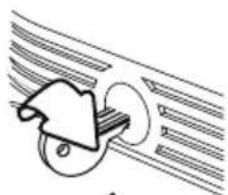
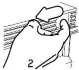
How to Open The Front Door

1 Insert the enclosed door-lock key and turn clockwise.
2 Press the door open button on the left side.
3 Front panel will be detached and you can replace the HDD.
IDOOR OPEN
natural_image
Simple line drawing of a stylized object resembling a helmet or gear, with motion lines indicating speed (no text or symbols)1
natural_image
Simple line drawing of a hand holding a small object, no text or symbols presentIDIS®
IDIS Co., Ltd.
For more information, please visit at
www.idisglobal.com
- Network Video Recorder
- Safety Precautions
- CAUTION
- WARNING
- AVERTISSEMENT
- Read Instructions
- Retain Instructions
- Cleaning
- Attachments
- Water and/or Moisture
- Ventilation
- Accessories
- Power Sources
- Power Cords
- Lightning
- Overloading
- Objects and Liquids
- Servicing
- Damage requiring Service
- Replacement Parts
- Safety Check
- Field Installation
- Correct Batteries
- Elevated Operating Ambient Temperature
- Reduced Air Flow
- Mechanical Loading
- Circuit Overloading
- Reliable Earthing (Grounding)
- HDMI Port Precautions
- In-Text
- User's Caution Statement
- FCC Compliance Statement
- WEEE (Waste Electrical & Electronic Equipment)
- Correct Disposal of This Product
- Copyright
- Registered Trademarks
- 1
- Part 1 – Introduction....7
- 2
- Part 2 - RAID Configuration .... 18
- 3
- Part 3 - Recovery Solution User Guide ....2 2
- 4
- Part 4 - Appendix ...... 2 3
- Product Features
- Accessories
- Front Panel
- ① SATA LED
- ② Status LEDs
- ③ Power Button
- ④ USB Ports
- • Storage Device Connection
- • Peripheral Device Connection
- Port Number of HDD Drive
- HDD Installation Precautions
- ⑤ Power LED
- ⑥ Front Door Lock
- Specifications on page 23.
- ⑦ Rack Mount Ears
- Rack Installation Precautions
- RAID Configuration Precautions
- Connections on the Front Panel
- Dimensions
- Rear Panel
- Rear Panel Connections
- Power Cable Connection
- eSATA Connection
- eSATA Compatibility List
- Storage Manufacturer Model
- Monitor Connection
- RJ-45 Video/Network Connection
- USB Port
- Audio Connection
- Introduction
- Getting Started
- RAID and Disk Information
- RAID Information
- Disk Information
- Event Log Viewer
- Basic RAID Configuration
- Part 3 - Recovery Solution User Guide
- Part 4 - Appendix
- Troubleshooting
- Specifications
- IDIS®
Brand : IDIS
Model : DS-IR-310D
Category : Video recorder