DR-1504P - Video recorder IDIS - Free user manual and instructions
Find the device manual for free DR-1504P IDIS in PDF.


| Product Type | Network Video Recorder (NVR) |
| Model | DR-1504P (also DR-1504P-A) |
| Brand | IDIS |
| Number of Channels | 4 channels |
| Video Compression | H.265 / H.264 |
| Recording Resolution | Up to 8 MP (depending on camera) |
| PoE Ports | 4 PoE ports (total PoE power up to 35W) |
| Dimensions (approx.) | 430 mm x 300 mm x 44 mm (1U rackmount) |
| Weight (approx.) | 3.0 kg |
| Power Supply | Internal switching mode power supply, 100-240V AC |
| Power Consumption | Max 35W (PoE inclusive) |
| Main Functions | Live monitoring, recording, playback, PTZ control, event monitoring, motion detection, smart search, network streaming, backup (USB/eSATA) |
| Storage | Internal SATA HDD (supports up to 2 HDDs, not included) |
| Display Output | HDMI, VGA (resolution up to 1920x1080) |
| Audio | Audio input/output (RCA), bidirectional audio support |
| Network | 10/100/1000 Mbps Ethernet, supports FEN, DDNS, UPnP |
| USB Ports | 2 USB 2.0 ports for backup/mouse |
| Security | Password protection, user permissions, 2FA, SSL, covert camera settings |
| Maintenance & Cleaning | Unplug before cleaning; use a damp soft cloth; no liquid cleaners |
| Safety Certifications | FCC Class A, CE, WEEE compliant |
| Spare Parts & Repairability | No user-serviceable parts; refer servicing to qualified personnel |
| Operating Temperature | 0°C to 45°C (32°F to 113°F) |
Frequently Asked Questions - DR-1504P IDIS
User questions about DR-1504P IDIS
0 question about this device. Answer the ones you know or ask your own.
Ask a new question about this device
Download the instructions for your Video recorder in PDF format for free! Find your manual DR-1504P - IDIS and take your electronic device back in hand. On this page are published all the documents necessary for the use of your device. DR-1504P by IDIS.
USER MANUAL DR-1504P IDIS
Network Video Recorder
Operation Manual
DR-1504P
DR-1504P-A
DR-1508P
DR-1508P-A
This operation manual contains basic instructions on installing and using DirectIP Network Video Recorder, an IDIS product. Users who are using this product for the first time, as well as users with experience using comparable products, must read this operation manual carefully before use and heed to the warnings and precautions contained herein while using the product. Safety warnings and precautions contained in this operation manual are intended to promote proper use of the product and thereby prevent accidents and property damage and must be followed at all times. Once you have read this operation manual, keep it at an easily accessible location for future reference.

- The manufacturer will not be held responsible for any product damage resulting from the use of unauthorized parts and accessories or from the user's failure to comply with the instructions contained in this operation manual.
- It is recommended that first-time users of DirectIP™ Network Video Recorder and individuals who are not familiar with its use seek technical assistance from their retailer regarding product installation and use.
- If you need to disassemble the product for functionality expansion or repair purposes, you must contact your retailer and seek professional assistance.
- Both retailers and users should be aware that this product has been certified as being electromagnetically compatible for commercial use. If you have sold or purchased this product unintentionally, please replace with a consumer version.
Safety Precautions

CAUTION
RISK OF ELECTRIC SHOCK DO NOT OPEN

CAUTION: TO REDUCE THE RISK OF ELECTRIC SHOCK, DO NOT REMOVE COVER (OR BACK). NO USER-SERVICEABLE PARTS INSIDE. REFER SERVICING TO QUALIFIED SERVICE PERSONNEL.

The lightning flash with arrowhead symbol, within an equilateral triangle, is intended to alert the user to the presence of uninsulated "dangerous voltage" within the product's enclosure that may be of sufficient magnitude to constitute a risk of electric shock.

The exclamation point within an equilateral triangle is intended to alert the user to the presence of important operating and maintenance (servicing) instructions in the literature accompanying the appliance.
| Symbol | Publication Description | |
 | IEC60417, No.5032 Alternating current | |
 | IEC60417, No.5031 Direct current | |
WARNING
Hazardous moving parts
Keep away from moving fan blades
AVERTISSEMENT
1. Read Instructions
All the safety and operating instructions should be read before the appliance is operated.
2. Retain Instructions
The safety and operating instructions should be retained for future reference.
3. Cleaning
Unplug this equipment from the wall outlet before cleaning it. Do not use liquid aerosol cleaners. Use a damp soft cloth for cleaning.
4. Attachments
Never add any attachments and/or equipment without the approval of the manufacturer as such additions may result in the risk of fire, electric shock or other personal injury.
5. Water and/or Moisture
Do not use this equipment near water or in contact with water.
6. Ventilation
Place this equipment only in an upright position. This equipment has an open-frame Switching Mode Power Supply (SMPS), which can cause a fire or electric shock if anything is inserted through the ventilation holes on the side of the equipment.
7. Accessories
Do not place this equipment on an unstable cart, stand or table. The equipment may fall, causing serious injury to a child or adult, and serious damage to the equipment. Wall or shelf mounting should follow the manufacturer's instructions, and should use a mounting kit approved by the manufacturer.

This equipment and cart combination should be moved with care. Quick stops, excessive force, and uneven surfaces may cause the equipment and cart combination to overturn.
8. Power Sources
This equipment should be operated only from the type of power source indicated on the marking label. If you are not sure of the type of power, please consult your equipment dealer or local power company. This equipment should be remain readily operable.
9. Power Cords
Operator or installer must remove power and TNT connections before handling the equipment.
10. Lightning
For added protection for this equipment during a lightning storm, or when it is left unattended and unused for long periods of time, unplug it from the wall outlet and disconnect the antenna or cable system. This will prevent damage to the equipment due to lightning and power-line surges.
11. Overloading
Do not overload wall outlets and extension cords as this can result in the risk of fire or electric shock.
12. Objects and Liquids
Never push objects of any kind through openings of this equipment as they may touch dangerous voltage points or short out parts that could result in a fire or electric shock. Never spill liquid of any kind on the equipment.
13. Servicing
Do not attempt to service this equipment yourself. Refer all servicing to qualified service personnel.
14. Damage requiring Service
Unplug this equipment from the wall outlet and refer servicing to qualified service personnel under the following conditions:
A. When the power-supply cord or the plug has been damaged.
B. If liquid is spilled, or objects have fallen into the equipment.
C. If the equipment has been exposed to rain or water.
D. If the equipment does not operate normally by following the operating instructions, adjust only those controls that are covered by the operating instructions as an improper adjustment of other controls may result in damage and will often require extensive work by a qualified technician to restore the equipment to its normal operation.
E. If the equipment has been dropped, or the cabinet damaged.
F. When the equipment exhibits a distinct change in performance – this indicates a need for service.
15. Replacement Parts
When replacement parts are required, be sure the service technician has used replacement parts specified by the manufacturer or that have the same characteristics as the original part. Unauthorized substitutions may result in fire, electric shock or other hazards.
16. Safety Check
Upon completion of any service or repairs to this equipment, ask the service technician to perform safety checks to determine that the equipment is in proper operating condition.
17. Field Installation
This installation should be made by a qualified service person and should conform to all local codes.
18. Correct Batteries
Warning: Risk of explosion if battery is replaced by an incorrect type. Replace only with the same or equivalent type. Dispose of used batteries according to the instructions. The battery shall not be exposed to excessive heat such as sunshine, fire or the like.
A manufacturer's maximum recommended ambient temperature (Tmra) for the equipment must be specified so that the customer and installer may determine a suitable maximum operating environment for the equipment.
20. Elevated Operating Ambient Temperature
If installed in a closed or multi-unit rack assembly, the operating ambient temperature of the rack environment may be greater than room ambient. Therefore, consideration should be given to installing the equipment in an environment compatible with the manufacturer's maximum rated ambient temperature (Tmra).
21. Reduced Air Flow
Installation of the equipment in the rack should be such that the amount of airflow required for safe operation of the equipment is not compromised.
22. Mechanical Loading
Mounting of the equipment in the rack should be such that a hazardous condition is not caused by uneven mechanical loading.
23. Circuit Overloading
Consideration should be given to connection of the equipment to supply circuit and the effect that overloading of circuits might have on over current protection and supply wiring. Appropriate consideration of equipment nameplate ratings should be used when addressing this concern.
24. Reliable Earthing (Grounding)
Reliable grounding of rack mounted equipment should be maintained. Particular attention should be given to supply connections other than direct connections to the branch circuit (e.g., use of power strips).
HDMI Port Precautions
- Use a certified cable marked with an HDMI logo when using HDMI. The screen may not display or a connection error may occur if you do not use a certified HDMI cable.
- It is recommended that you use the following HDMI cable type. -High-speed HDMI Cable -High-speed HDMI Cable with Ethernet
In-Text
Symbol Type Description


Caution Important information concerning a specific function.
Note Useful information concerning a specific function.
User's Caution Statement
Caution: Any changes or modifications to the equipment not expressly approved by the party responsible for compliance could void your authority to operate the equipment.
FCC Compliance Statement
THIS EQUIPMENT HAS BEEN TESTED AND FOUND TO COMPLY WITH THE LIMITS FOR A CLASS A DIGITAL DEVICE, PURSUANT TO PART 15 OF THE FCC RULES. THESE LIMITS ARE DESIGNED TO PROVIDE REASONABLE PROTECTION AGAINST HARMFUL INTERFERENCE WHEN THE EQUIPMENT IS OPERATED IN A COMMERCIAL ENVIRONMENT. THIS EQUIPMENT GENERATES, USES, AND CAN RADIATE RADIO FREQUENCY ENERGY AND IF NOT INSTALLED AND USED IN ACCORDANCE WITH THE INSTRUCTION MANUAL, MAY CAUSE HARMFUL INTERFERENCE TO RADIO COMMUNICATIONS. OPERATION OF THIS EQUIPMENT IN A RESIDENTIAL AREA IS LIKELY TO CAUSE HARMFUL INTERFERENCE, IN WHICH CASE USERS WILL BE REQUIRED TO CORRECT THE INTERFERENCE AT THEIR OWN EXPENSE.
WARNING: CHANGES OR MODIFICATIONS NOT EXPRESSLY APPROVED BY THE PARTY RESPONSIBLE FOR COMPLIANCE COULD VOID THE USER'S AUTHORITY TO OPERATE THE EQUIPMENT.
THIS CLASS OF DIGITAL APPARATUS MEETS ALL REQUIREMENTS OF THE CANADIAN INTERFERENCE CAUSING EQUIPMENT REGULATIONS.
WEEE (Waste Electrical & Electronic Equipment)
Correct Disposal of This Product
(Applicable in the European Union and other European countries with separate collection systems)

This marking shown on the product or its literature, indicates that it should not be disposed with other household wastes at the end of its working life. To prevent possible harm to the environment or human health from uncontrolled waste disposal, please separate this from other types of wastes and recycle it responsibly to promote the sustainable reuse of material resources.
Household users should contact either the retailer where they purchased this product, or their local government office, for details of where and how they can take this item for environmentally safe recycling.
Business users should contact their supplier and check the terms and conditions of the purchase contract. This product should not be mixed with other commercial wastes for disposal.
Copyright
© 2022 IDIS Co., Ltd.
IDIS Co., Ltd. reserves all rights concerning this operation manual.
Use or duplication of this operation manual in part or whole without the prior consent of IDIS Co., Ltd. is strictly prohibited.
Contents of this operation manual are subject to change without prior notice.
Registered Trademarks
IDIS is a registered trademark of IDIS Co., Ltd.
Other company and product names are registered trademarks of their respective owners.
The information in this manual is believed to be accurate as of the date of publication even though explanations of some functions may not be included. We are not responsible for any problems resulting from the use thereof. The information contained herein is subject to change without notice. Revisions or new editions to this publication may be issued to incorporate such changes.
The software included in this product contains some Open Sources. You may obtain the complete corresponding source code depending on whether or not the source is publicly available under a license policy. Go to System Setup - About page for more information. This product includes software developed by the University of California, Berkeley and its contributors, and software developed by the OpenSSL Project for use in the OpenSSL Toolkit (http://www.openssl.org/). Also, this product includes cryptographic software written by Eric Young (eay@cryptsoft.com), and software written by Tim Hudson (tjh@cryptsoft.com).
1
Part 1 - Getting Started ....9
Setting Password....9
Setup Wizard....9
Camera Registration....13
Camera Scan Button....14
Camera View Buttons....16
Camera List Area 17
Video Display Area 18
Apply/Cancel Buttons 19
Diagnosis Process 19
Camera Registration Mode....20
Login 20
Live Menu 22
Zoom....24
PTZ Control 24
Event Monitoring 26
Covert Camera 26
Context Menu Access 26
Edit Group 27
Video Recording....27
Panic Recording....27
Video Recording Playback ....28
All Channel Playback....28
2
Part 2 - Configuration....29
Menu Use....29
Text Input via Virtual Keyboard 30
Batch Assignment....30
Mouse 30
System Setup 31
General 31
Date/Time 32
User 33
Security....36
Storage 37
Self-Diagnosis....38
Custom Value 39
About....39
Camera Setup 40
Registration....40
General 42
Advanced Setup 43
Stream I....49
Stream II....50
Maintenance....51
Record Setup....52
General 52
Schedule....53
Pre-Event 55
Event Setup....55
System_Event....55
Camera System 56
Camera System_Video Loss....57
Camera System_Recording Fail 57
Camera System_PIR 58
Video-Analytics 59
Video-Analytics_Motion....59
Video-Analytics_Trip Zone....60
Video-Analytics_Tampering 62
Video-Analytics_Auto Tracking 63
Network Setup 64
General 64
WAN....64
VIN 67
FEN....68
Firewall 69
Notification Setup....69
Schedule....69
Callback 70
Mail....71
Push....72
HTTP 72
Display Setup 73
OSD 73
Main Monitor 74
Status Setup ....74
Camera 74
Device 75
System....75
Storage 76
Network 77
Part 3 - Search....79
Time-Lapse Search 79
Search Menu....79
Context Menu....80
Clip Copy 81
Event Log Search....82
Overlapped Recording Search 83
Memo....84

This document covers the 4- and 8-channel network video recorders. The NVRs are identical except for the number of cameras that can be connected and the number of cameras that can be displayed. For simplicity, the illustrations and descriptions in this document refer to the 4-channel model.
Setting Password
1 The users must first run the system and then be required to set the password for the admin user account.
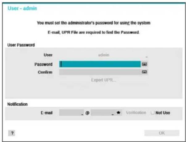

- It does not allow a user to run the system without a password.
- Click the question mark button on the bottom left corner and refer to the instruction on setting up a password.
- An email address and UPR files are required to find the password. Otherwise, you may not be able to find your password when you enter the incorrect information.
Setup Wizard
Setup Wizard lets you configure basic settings required for operating the system.

Setup Wizard only appears during initial booting. When you login as an administrator account after initial booting, you can use Wizard to go to Live menu and select Wizard.
1 Select a system language.


Select Cancel from any of the Wizard screen to cancel the setup process and return to the main setup menu.
Quick Wizard
1 Select Quick Wizard.
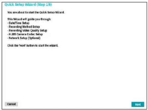
2 Specify the current date and time and then click Next.
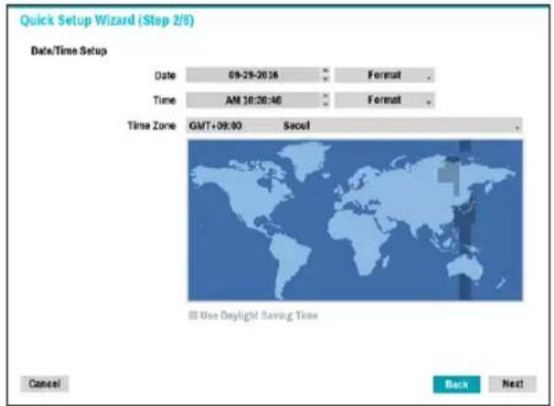

- The new date and time settings will only be applied after clicking Next.
- For more information on date and time settings, refer to the Date/Time section under System Setup on page 31.
3 Choose the desired Recording Method and click Next.
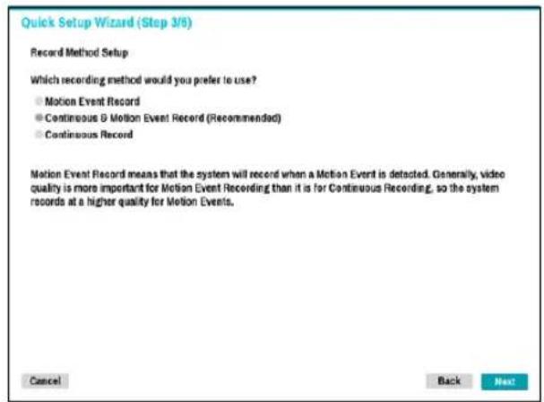
4 Choose the desired Recording Quality and click Next.
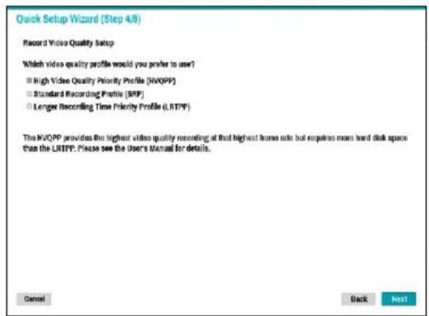

- Higher recording quality uses up more disk space.
- Recording resolution is determined based on the selected recording quality.
– High Video Quality Priority Profile: Very high
– Standard Recording Profile: High - Longer Recording Time Priority Profile: Standard
—Recording resolutions used under each recording method and record video quality setting are as follows:
| High Video Quality Priority Profile | Standard Recording Profile | Longer Recording Time Priority Profile | |
| Motion Event Record | Profile 1 Profile 2 Profile 3 | ||
| Continuous & Motion Event Record | Profile 2 (Continuous) / Profile 1 (Motion) | Profile 3 (Continuous) / Profile 2 (Motion) | Profile 4 (Continuous) / Profile 3(Motion) |
| Continuous Profile 1 Profile 2 Profile 4 | |||
5 Choose the desired codec and click Next.
Quick Setup Wizard (Step 5/6)
H.265 Camera Codec Setup
Select default codec for H.265 camera
● H.265 only mode (Optimal mode for storage space and network bandwidth)
H.265 / H.264 Hybrid mode (Optimal mode for storage space and remote monitoring)
H.265 only mode reduces both storage space and network bandwidth. Be aware that H.265 does increase processor load on remote monitoring PCs or Mobile devices.
H.265 / H.264 hybrid mode reduces both storage space and processor load for remote monitoring PCs or mobile devices. Recorded video is stored using the higher compression ratio of H.265, however, video streams to remote monitoring devices are compressed using H.264 which requires less processor power on remote monitoring PCs or mobile devices.
Cancel
Back
Next
6 Click Finish to exit Quick Wizard.
Quick Setup Wizard (Step 6/6)
Now you have completed setup for basic operation.
Click the 'Finish' button to finish the wizard.
or click the 'Go to Network Setup' button to start the Network Setup.
Cancel
Go to Network Setup
Finish
Network Wizard

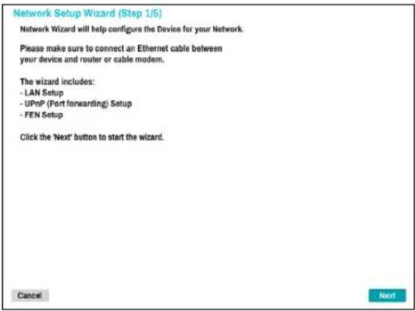
After exiting from Quick Wizard, the network with Network Wizard will start automatically.
1 Select Network Wizard.
2 Specify whether the system is connected to the Internet and click Next.
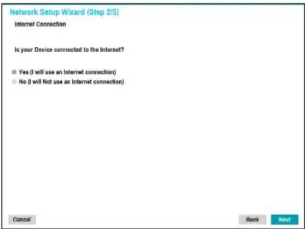

If you have chosen No, wait for the test to finish and then click Finish to exit Network Wizard.
3 Select Network Configuration and then click Next. Select either Auto Configuration or Manual Configuration and then click Test to test the system's current network configuration.
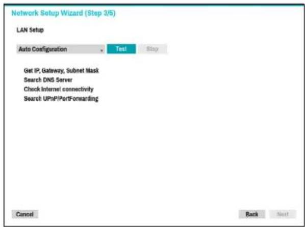

- This test must be performed before proceeding to the next step.
- If the NVR is on a network connected to a network that has a DHCP server, selecting Auto Configuration retrieves LAN settings such as IP and DNS addresses automatically. Selecting Manual Configuration, on the other hand, lets you specify the settings manually.
- UPnP support device not found. If this error message is displayed, check to see if the IP router (or NAT) supports UPnP and if UPnP has been enabled. For more information about the router's UPnP function, refer to the router's operation manual.
4 Enter in the Device Name field the NVR name to be registered on the FEN server and then click Check to check its availability.
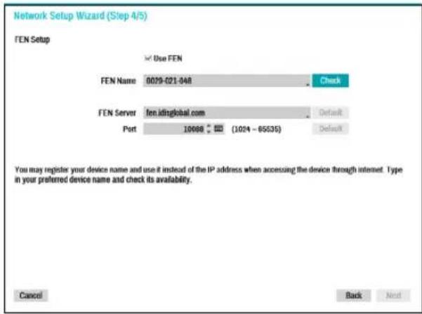

- The device name you register on the FEN server will be a unique name used to identify the NVR. Once registered, the name can be used to access the NVR directly from clients such as the IDIS Center. Check the name's availability to complete the registration process. The Finish button will then become activated.
- You will be prompted with an error message if you do not enter a name for the NVR or enter a name already registered on the FEN server.
- Depending on the network environment, FEN services may not be active and therefore prevent the NVR from connecting to the network. In this case, you will need to manually configure the ports. For more information on port configuration, refer to Network Setup on page 64.
5 Click Finish to exit Network Wizard.
![Network Setup Wizard [Step 5/5] You have now completed your network setup. Click 'Finish' to complete the setup wizard Cancel Finish](/content/2026/05/1015987/images/4d33efa297a299d4f9269c979a212e61ba748031db042b5343a034641e2a547d.jpg)
Camera Registration
Once Network Setup Wizard is complete, live mode screen appears. While in live mode, right-click on the mouse and select Camera Registration to run the Camera Registration mode. It allows you to scan for the cameras connected to the NVR.
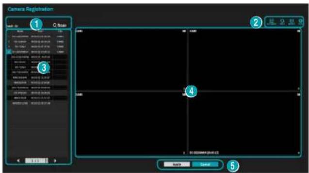
| 1 | Camera Scan Button |
| 2 | Camera View Menus |
| 3 | Camera List Area |
| 4 | Video Display Area |
| 5 | Apply/Cancel Buttons |
You can also register cameras on the remote program. For more information on the remote camera registration, refer to Registration on page 13.
Camera Scan Button
You can scan and search and register cameras that were not detected automatically or third party cameras.
Pressing the Scan button displays the following sub-menu.
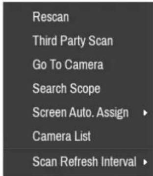
Rescan
Scans for DirectIP™ cameras that were not scanned automatically.
Third Party Scan
Scans for IDIS Open cameras that do not support automatic scan feature.
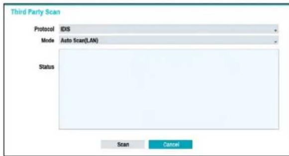
- Protocol: Select the protocol used by the camera (or video encoder) you wish to search for.

- Some functions may not be supported for the third-party cameras depending on their protocol and model.
• Mode: Select the scan mode.
- Auto Scan (LAN): Lists cameras in a LAN environment. If Auto Scan (LAN) fails to recognize a camera, try using IP Address Scan instead.
- IP Address Scan: Enter the IP address of a camera. The NVR scans for the camera matching the specified address. If you enter IP address's range, the NVR scans for cameras falling under the specified address's range. By specifying an IP address, you can also specify which port to use with the Remote Admin feature. It is recommended that the camera not be networked via DHCP (Dynamic Host Configuration Protocol). If the camera is networked via DHCP, connection to the camera may not be made properly depending on changes in the external network environment.
1 Select Scan to commence scanning.

Only cameras that are connected to the NVR via VIDEO IN ports can be scanned and registered.
2 Select a camera from the scan list and then select Add Camera. The device login window will appear.
3 Enter a User ID and a Password for the selected camera.
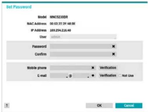
Set Camera Password
For IDIS protocol cameras that support changing and finding the camera password, you must set the camera password at the time of initial camera registration. The email information is used to change and find the camera password.
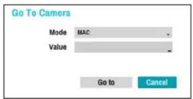
Go To Camera
Moves the focus automatically to the camera using the MAC addressa and model of camera in the camera list.
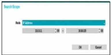
Search Scope
Filters the cameras in the camera list depending on the search scope such as specified IP address rang
Screen Auto. Assign
Assigns the detected cameras on the video display area.
Camera list
By using the camera information file, .csv, the user can register the cameras easily.
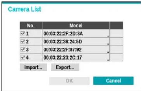
- Export : Button : Exports the list of camera information on USB as a .csv file
- Import : Button : Imports a camera information file, .csv file. The user can edit a csv file directly.

- A column indicates camera number, B column the camera MAC address, C column the Video In port of the video encoder in the .csv file. C column indicates only for video encoders. If camera information displays as follows: 5,00:11:22:18:30:20,3, 5 = CAM 5, 5,00:11:22:18:30:20 = MAC address, 3 means video encoder.
- Before using this feature, the cameras must be scanned first. If the cameras to be registered do not exist in the list, the camera cannot be registered.
- This feature is not supported for the third-party cameras.
Scan Refresh Interval
Configures the refresh interval to scan the camera. If the interval is short, camera scan results are refreshed more frequently. However, if the interval is long, it is advantageous to scan cameras on a wide network.
Camera View Buttons
- ALIGNMENT ☐ Button: Realigns camera screens displayed on the video display area in the order of Video In port connections.
- RESET Button: Refreshes the video display area and the camera list.

Selecting RESET clears all scanned devices from the list.
- Bitrate 📋 Button: Displays the following window to change the bitrate allocation for each channel.
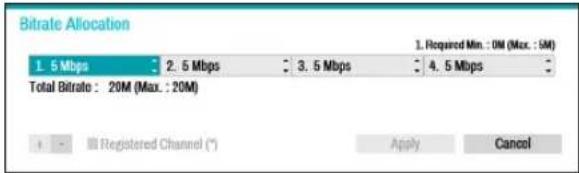
When registering the camera, you can set the stream as much as the performance (bitrate) assigned to the channel. If high performance (bitrate) is not allocated, Quality, IPS and Resolution can be low. If a channel has a camera already registered, bitrates may not be lower than current stream settings. You can change the bitrate by pressing the + - button at the bottom left. Only the bitrate of the registered camera can be changed by checking the registered channel (*).
- ToolButton: Displays network camera tool window to run a camera-related actions. There are Authentication, Screen Assignment and Camera Protocol Change for actions.
1 Select an Action to execute.
2 Select a camera from the list and press the Apply button.
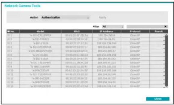
√ IDIS cameras can be detected automatically but IDIS protocol cannot be detected automatically. We recommend you use the DirectIP protocol to detect the cameras automatically. When you change the protocol, the camera reboots and then you can register the camera on the NVR. For more information on the settings, please refer to the network camera manual.
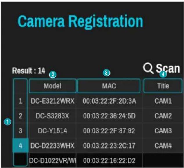
Camera List Area
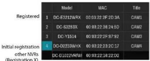
other
| Registered | 1 | 2 | 3 | 4 | |---|---|---|---|---| | Model | DC-E3212WRX | DC-S3283X | DC-Y1514 | DC-D2235WHX | | MAC | 00:03:22:2F:2D:3A | 00:03:22:36:24:5D | 00:03:22:2F:87:82 | 00:03:22:23:2C:17 | | Title | CAM1 | CAM2 | CAM3 | CAM4 | | (Registration X) | DC-D1022VR/WI | DC-D1022VR/WI | DC-D1022VR/WI | DC-D1022VR/WI |① Screen Position/Registration Status: Identifies the camera's position in the video display area. A blue background indicates a camera that is available for registration. A gray background indicates an already registered camera. Other registered cameras are shown in black background.
② Model: Indicates the camera's model.
③ MAC: Displays the 12 digits of the camera's MAC address.
④ Title: Indicates the camera's name. Changing a camera's name in the video display area updates the camera list as well.

- Select Model and MAC to sort in ascending/ descending order. The registered cameras are displayed at the top of the list.
- Selecting Title changes MAC address to IP and IP address changes to MAC.
Following options can be accessed by right-clicking on a camera list entry:
- Add/Remove Camera: Adds or removes the selected camera. The Add Camera option is inactive if the camera has already been added to the screen.
- Authentication: Enter the necessary camera login info. This option is inactive for DirectIP™-cameras because they do not require logins. This option is inactive for IDIS protocol only if the password is set.
Video Display Area
Left-click on the video display area to toggle between split screen and single screen modes.
Drag the camera screens around to rearrange them.
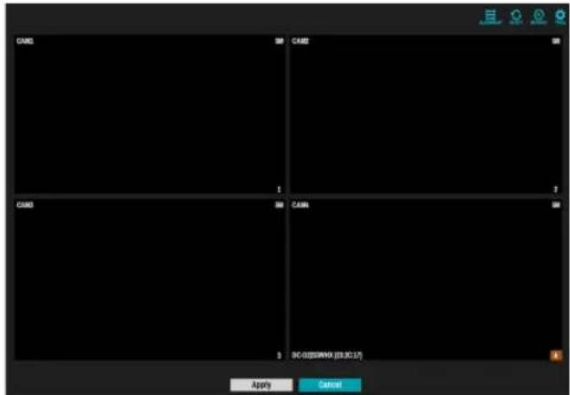
Camera Screen
![CAM1 ① ④ 1M ② DC-Y1513 [26:13:DC] ③ 1](/content/2026/05/1015987/images/ab0793de70281c9f02bfeda48b95f9eb13da372a821b220efb7609b0b32d1c38.jpg)
① Camera Title
Indicates the camera's title. Left-click on the title to edit the camera's title.
![Title CAM1 1 2 3 4 5 6 7 8 9 0 - = \ q w e r t y u i o p [ ] a s d f g h j k l ; ' z x c v b n m , . / space OK Cancel](/content/2026/05/1015987/images/17859e5d9999254f6657a624774030330285f022a12a91c14f30e198c9775000.jpg)
② MAC Address
Camera's model and MAC address are shown if the camera has not been registered to the NVR.
③ Screen Position/Registration Info
Flashes in orange if the camera has not been registered to the NVR.

• Information is not indicated on the bottom of the screen for cameras already registered to the NVR, and the Screen Position/Registration Info icon is shown with a black background.
- Screen Position/Registration Info icon for cameras registered to another NVR is shown with a steady orange background on top of a gray screen.
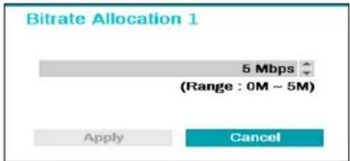
④ Bitrate Allocation
Indicates the performance (bitrate) allocated to the channel. Left-click on the upper right corner of the screen to change the bitrate.
Camera Menu
Right-click on the video display area to bring up the camera menu.
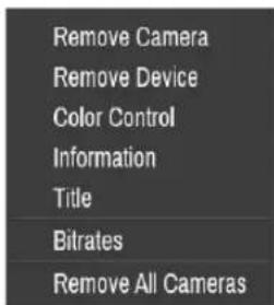
- Remove Camera: Removes the registered camera.
- Remove Device: Removes the registered encoder.
- Color Control: Adjusts the camera's color settings.
- Information: Displays the camera's basic information.
• Title: Edits the camera's title. - Bitrates: Changes the bitrate allocated to the channel.
- Remove All Cameras: Removes all registered cameras.

You can drag & drop to add or remove cameras.
Apply/Cancel Buttons
While in Camera Registration mode, select Apply to register all changes. When selecting Apply, the following message will be displayed. You can activate or deactivate Self-diagnosis.
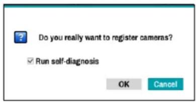
Select Cancel to exit Camera Registration mode without applying the changes.

It is not possible to register a camera that has already been registered to a different NVR.
Diagnosis Process
When the camera is registered to the NVR, Self-diagnosis runs automatically for the new registered and changed cameras. If Self-diagnosis is processing, Diagnosis Processing message will be displayed.
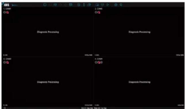
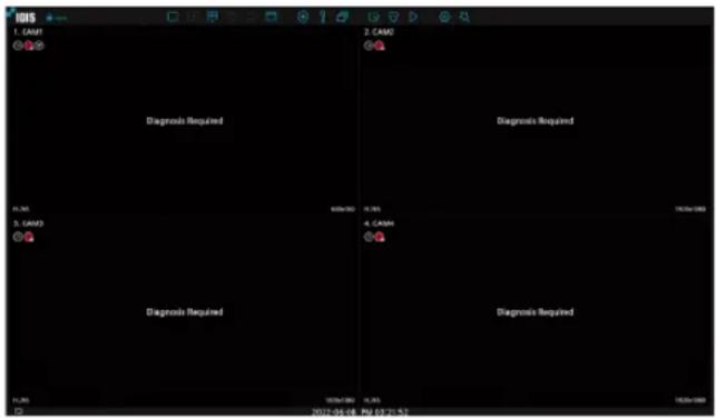
If Self-diagnosis is failed, Diagnosis Required message will be displayed. In this case, you can run Self-diagnosis manually.
Camera Registration Mode
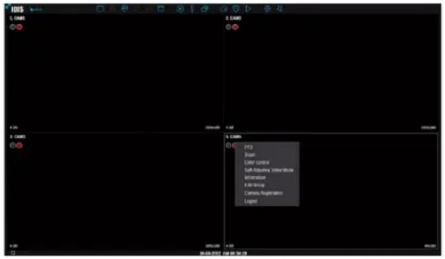
While in Live mode, right-click and select Camera Registration.
Login
Configuring the NVR's settings and accessing its searching and other functions require an authorized user login.
1 Bring up the Live menu and click on icon using the mouse to log in.
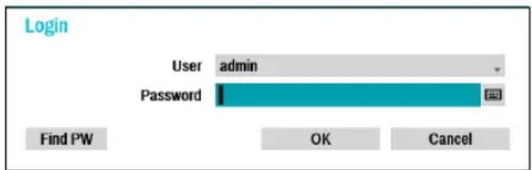
2 Select a user, enter the password, and then select OK.

- Click on the button next to the password field using the mouse. This will bring up a virtual keyboard you can use to assign a password. For more information on using the virtual keyboard, refer to the Text Input via Virtual Keyboard on page 30.
3 To log out, bring up the Live menu and click on icon using the mouse.
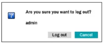
Find Password
If you do not know the password, select FIND PW. You can set a new password.
1 Enter a user, registered email and then select Get Verification Code.
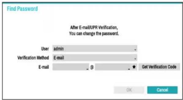
2 Enter Verification Code and select OK.
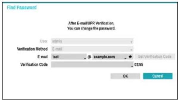

- Select the question mark button at the bottom left corner of the screen to refer to the password settings instructions.
- The password must be entered only with the virtual keyboard.
- FEN service must be enabled to use Find Password function.
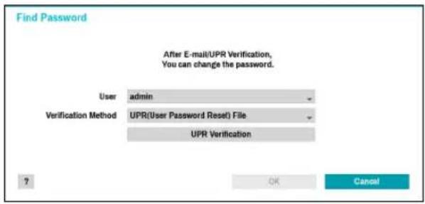
3 Enter an UPR(User Password Reset) verification and then click on UPR Verification button.
4 Select the UPR file and then click on Import button.
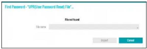

- To use UPR function, the UPR file must be saved in advance. For more information on saving the UPR file, refer to User on page 33.
- You can reset the password using an encrypted UPR (User Password Reset; filename extension *.upr) file.
- It can be used as USB flash driver on local pc, but not remotely.
- Only files exported from the same device are available.
- If you lose the UPR file and change the password of the NVR, the UPR file may not be used.
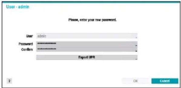
5 To set a new password, click the question mark button in the lower left corner and follow the instructions.
Live Mode
Live Menu
Placing the mouse pointer near the top portion of the screen displays the Live menu.
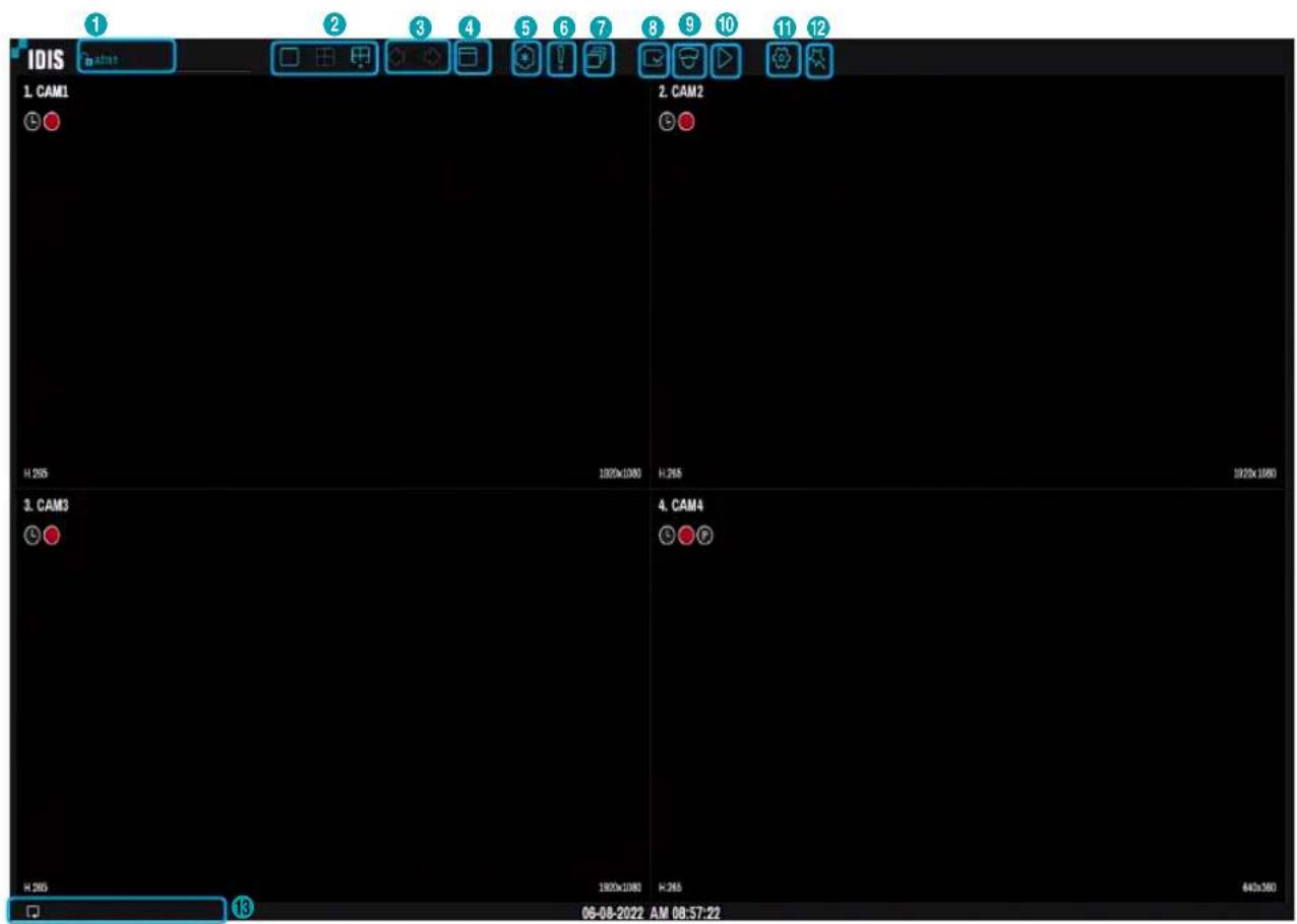
| 1 | Login/Logout | 2 | Layout | 3 | Previous Group, Next Group | 4 | Display |
| 5 | Freeze | 6 | Panic Recording | 7 | Sequence | 8 | Status |
| 9 | Select Camera | 10 | Search Mode | 11 | Setup | 12 | Wizard |
| 13 | Status Indication |
① Login/Logout
Log into and out from accounts. If in the logged in state, the account ID is shown. If in the logged out state, the login icon is shown.
② Layout
Used to change the screen layout to single screen, 1x2, corridor format(1x3) or 2x2.

Corridor Format: Divides the screen into 3 panes. This format displays vertically and is set to display the optimized video of the camera when using the camera's pivot feature. This is particularly effective when monitoring hallways, passages, and other confined spaces.
③ Previous/Next Group
Loads the previous/next screen group.
④ Display
• Full Screen On/Off: Enables the full screen mode.
- Camera OSD On/Off: Enables/disables the camera OSD feature.
- Status OSD On/Off: Enables/disables the status OSD feature.
- Aspect Ratio On/Off: Setting On displays video on the camera screen in its original ratio.
⑤ Freeze
Freezes the screen. Select Freeze again to unfreeze.
⑥ Panic Recording
Activates/deactivates Panic Recording.
⑦ Sequence
Selecting the Sequence icon ☐ while in Live mode changes to the sequence mode. To exit, select Sequence icon ☐ once more. The icon is displayed on the upper right part of the screen while Sequence is in progress.
Full Sequence
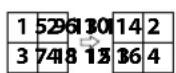
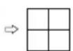
Displays all channels in sequence while in Live mode (single and split screen settings). In order to use the Full Sequence feature, Full Sequence (Display Setup - Main Monitor > Sequence) must first be enabled.
e.g.) Full Sequence in 2x2 split screen mode
Cameo Sequence
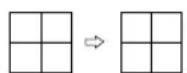
In Cameo Sequence mode, only the bottom right screen in a split screen setup changes sequence. In order to use the Cameo Sequence feature, Cameo Sequence (Display Setup - Main Monitor > Sequence) must first be enabled.
e.g.) Cameo Sequence in 2x2 split screen mode


- If using the Full Sequence setting, page numbers appear on the system status area on the upper right part of the screen, next to the Sequence icon.
- If using the Cameo Sequence setting, pages are skipped under the following circumstances:
- If all cameras included in the page are deactivated.
- If there are no video signals.
- If the page contains "covert" cameras.
- If the user does not have permission to view feeds from the cameras.
⑧ Status
Displays the status window for NVR's system and device.
⑨ Select Camera
Displays the selected camera in a single screen format.
⑩ Search Mode
- Time-Lapse Search: Select Search Mode > Time-Lapse Search to search for and play back saved data directly from the record table.
- Event Log Search: Select Search Mode > Event Log Search to search for event logs and play back associated event recordings.
⑪ Setup
Used to access the Setup menu.
⑫ Wizard
Launches the Setup Wizard.
Running the Wizard lets you configure basic settings required for operating the system.
⑬ Status Indication
Displays system status icons.
Status Indication
| Indicates connection to the NVR from a remote program. | |
| Indicates a zoomed in state. | |
| Indicates Freeze is in use. | |
| Indicates Sequence is in use. | |
| Indicates an event monitoring. | |
| Indicates HDD use. The icon to the left is shown if using the overwrite setting. Otherwise, remaining HDD space is shown as a percentage value. |
Zoom
While in Live mode, right-click and select Zoom.
When a zoom frame appears on the selected channel, right-click on the mouse to zoom in. Use the arrow buttons to position the frame. When Zoom is activated, icon is on the status bar located on the upper right corner of the system.

- In Full Screen mode, activating Zoom automatically selects the current channel.
- To restore the channel to normal size, press the Zoom button again.
PTZ Control
While in Live mode, right-click and select PTZ from the context menu.
The P icon will begin to flash on the selected camera's OSD window.
You can change the direction by dragging on the mouse.
Also, it's possible to use the mouse wheel to zoom in/out.
You can change the direction by dragging on the mouse.
Also, it's possible to use the mouse wheel to zoom in/out.

- Logging in with an account that has PTZ Control Authority is necessary in order to control PTZ cameras.
- A message will prompt if there is no PTZ camera displayed on the Live screen.
- To exit PTZ mode, press the PTZ button of Context menu again.
Setting Up a PTZ Preset
While in PTZ mode, select the icon to display the Set Preset window and assign the current position as a desired preset number.
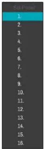
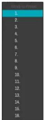
While in PTZ mode, select the icon to display the Move to Preset window.
Select a preset number to move the current PTZ camera to the selected preset's position.
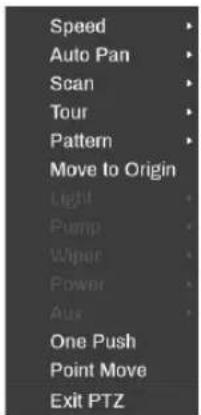
In PTZ mode, selecting a camera and then right-clicking on the mouse loads the Advanced PTZ screen as shown below. This menu lists Speed, Auto Pan, and other advanced PTZ camera control options available for the camera. Also selecting Point Move button moves PTZ camera to the point that the user clicks. Options that are not available for the selected PTZ camera remain inactive.

You can use the mouse to control PTZ cameras. Left-click on the mouse and drag to move the camera in the desired direction and use the mouse wheel to zoom in/out.
While in PTZ mode, place the mouse pointer close to the bottom edge of the screen to display the PTZ Tools window.
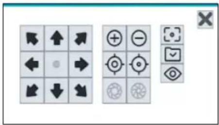
| PTZ Camera Pan and Tilt | |
| Zoom In/Out | |
| Focus Near / Far | |
| IRIS Open / Close | |
| One Push | |
| Set / Move to Preset | |
| Device Menu supported by the camera |

- The exact PTZ protocol supported by the camera must be specified in order to use the NVR's PTZ controls.
- Drag and drop to reposition the PTZ Tools window.
- Select the ✗ icon to hide the PTZ Tools window.
Event Monitoring
When an event occurs, the NVR automatically changes to the camera screen linking event monitoring and shows the icon on the system status area on the upper right portion of the screen. To use the Event Monitoring feature, navigate to Display Setup > Main Monitor and enable Event Monitoring. Event Monitoring remains in effect throughout the entire Linked Time. After that, the NVR will return to the previous screen if a new event does not take place. Pressing the Layout or a Camera button before the end of the Linked Time reverts the system to Live mode.
Covert Camera
Use this feature to assign Covert Camera View permissions.
Navigate to Camera Setup > General and designate cameras as Covert 1 or Covert 2.
- Covert 1: Hides images from the camera in Live mode but does indicate the camera's title and status via icons.
- Covert 2: The camera is indicated as being inactive. Images from the camera are not shown. Camera title and status icons are not shown.

Users that have a cover Covert Camera View are able to view both images from and status icons for all Covert 1 and Covert 2 cameras.
Context Menu Access
While in Live mode, right-click on the mouse to display the Context Menu window.
- PTZ: Access PTZ controls.
- Zoom: Zoom in.
- Color Control: Select a channel to display its Color Control window. Adjust the selected camera's brightness, contrast, saturation, and hue settings.
- Self-Adjusting Video Mode : Select the image preset (Natural, Vivid, Noise Reduction) and you can control it directly.
- Information: Select a network channel to display information about the selected channel's device.
- Edit Group: Rearrange the split screen layout.
- Camera Registration: Activate Camera Registration mode.
- Login/Logout: Log into the account or log out of the account.
Edit Group
Edit Group lets you customize split screen pages in both Live and Search modes.
1 While displaying a split screen page, select the Edit Group option from the context menu. A yellow border is drawn around the page. Use the mouse to select a different page.
2 Right-click on the mouse to select a camera on the screen with yellow lines. Selected camera is then loaded on to the selected page. Repeat to assign other channels to the page.
3 Right-click on the mouse to exit Edit Group.
Alternatively, press the Menu button and then select Exit Group Edit to exit.

Edit Group will terminate automatically after 15 seconds of inactivity.
Video Recording
Video recording will only take place if all the connections are made correctly as per information contained in Part 2 of this operation manual.
For more information on video recording settings, refer to the Record Setup on page 52.
Panic Recording
Select Live or Search menu's Panic Recording 📁 icon to commence panic recording on all registered cameras. To stop Panic Recording, select the Panic Recording 📁 icon again. If the Panic Recording Duration option under Record Setup > General has been configured, Panic Recording will automatically terminate after the specified duration of time has elapsed. For more information, refer to the Record Setup on page 52.

- Panic Recording takes place irrespective of any recording schedule set up by the user.
- Panic Recording video profile from Record Setup – General applies to all Panic Recording videos.

Panic Recording will not take place if recording mode is not set to Recycle and the HDD has reached 100% of its capacity.
Video Recording Playback
You can play back video recordings by using mouse.

- Login with an account that has search permission is needed to playback video recordings.
- The initial video playback point in Search mode is the recording's last playback point or the end of the recording data.
- Covert protection on cameras also applies to video recording playback.
All Channel Playback
1 Place the mouse pointer near the top portion of the screen.
2 Select the Search Mode icon and then select Time-Lapse Search or Event Log Search.
3 The selected search mode will be initiated.
For more information on data search, refer to the Part 3 - Search on page 79.
Menu Use
Information contained in this section (Menu Use) applies to all other instructions found throughout Part 3 - Configuration.
Menu Icon
| Use the virtual keyboard to enter text. | |
| - | Type the text. |
| ▼ | Open a drop-down menu. |
| X Delete the item. | |
| ◆ | Change the order of table entries. |
| Change the range of values. | |
| + | Add new items or works. |
| ★ | Indicate that there are predefined items for convenience. |
| ... | Display the submenu or pop-up window. (except for information, error and alert windows) |
Login with an ID that has permission to access the setup menu is needed to access and make changes to the Setup menu.

When using Use 2FA feature, registered mobile device must be authenticated before entering the setup menu. For more information on 2FA function, refer to Use 2FA on page 36.
1 While in Live mode, select Live menu > Setup using the mouse.
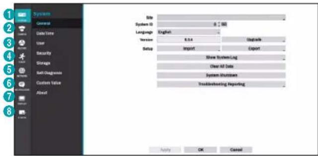
| 1 | System Setup |
| 2 | Camera Setup |
| 3 | Record Setup |
| 4 | Event Setup |
| 5 | Network Setup |
| 6 | Notification Setup |
| 7 | Display Setup |
| 8 | Status Setup |
2 Left-click on the option using the mouse.
3 Change the setting and then select Apply or OK to save the change.

To apply default settings, select the Default button located on the left bottom corner of the setup window.
Text Input via Virtual Keyboard
Click on the key using the mouse.
![Site 1 2 3 4 5 6 7 8 9 0 - = \ q w e r t y u i o p [ ] a s d f g h j k l ; ' z x c v b n m , . / space OK Cancel](/content/2026/05/1015987/images/3bc42df76e7c769668eb070ef7ce28d27091843781526f21f7ab23e50add9dc0.jpg)
| Toggle case. | |
| Deletes the character to the left of the cursor. | |
| Deletes the character to the right of the cursor. | |
| Converts keyboard. |
Batch Assignment
Certain table-format menus such as the shown in the Camera Setup on page 40 allow you to change the title value. In this case, changing the title value simultaneously changes all other entry values on the same row.
Mouse
Using a mouse makes it easier to configure the settings. A mouse lets you make selections faster and use its wheel to scroll through long menus. You can also use the mouse wheel to increase/decrease numerical values.
System Setup
Refer to the Menu Use on page 29 for basic information on using the Setup menus.
General
This Setup menu contains general system options.
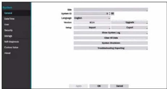
- Site: Used to enter a description about the system's installation site (no description by default). You can edit the information using the virtual keyboard.
- System ID: Used to identify the NVR apart from other NVRs.

The default System ID is 0 and can be changed to a value between 0 and 99. The System ID can also be entered using the virtual keyboard.
• Language: Choose a language.
• Version: Indicates the software version.
- Upgrade: Upgrade the system. Selecting the USB port displays the USB search window. You will then be able to select an upgrade package and upgrade the system. Once the upgrade is completed, the NVR will reboot automatically.
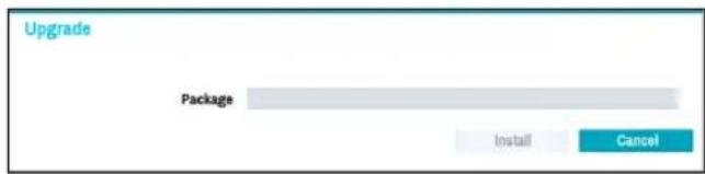

When using Use 2FA feature, registered mobile device must be authenticated to upgrade the system. For more information on 2FA function, refer to Use 2FA on page 36.
- Setup: Exports current NVR settings or imports existing settings.
- Import: Decide whether to import network settings as well. If you do not wish to change the current network settings, do not select Include Network Setup.

Selecting Setup Import does not change the settings below.
• Time-related settings (Date/Time, Time Zone, and Use Daylight Saving Time)
•Camera-related Advanced Settings settings
- Camera-related Stream settings (Only if the resolution is different from the camera in exporting) If users and groups are deleted, existing user settings are retained.
- Export: Exports the current system settings to a storage device connected to the system's USB port. You can designate a File Name for the export file.

For USB flash memory devices, the NVR supports the FAT32 file format only.
- Show System Log: Displays a searchable list of 5,000 most recent system log entries. For more information on types of system log entries, refer to the System Log Types in the installation manual. The 🎨 icon appears next to log entries originating from a remote source. To export the system log, select the Export at the bottom of the screen and then designate a file name.
Part 2 - Configuration
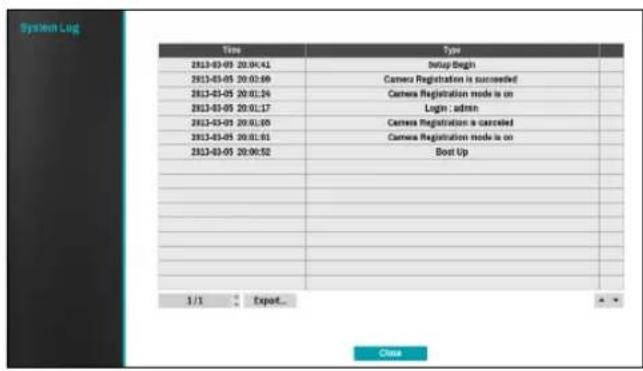

In order to display the system_log.txt file, you must use the correct character encoding settings and use a fixed-width font.
- Clear All Data: Erases all recording data. Selecting Clear All Data displays a confirmation window. Select Clear to proceed.

- Before you perform Clear All Data, make sure you are not accidentally deleting important data. Erased data cannot be recovered.
- Clear All Data does not affect the system log. Instead, the Clear All Data event will be added to the log.
- System Shutdown: Shuts down the system. When prompted, select System Shutdown.
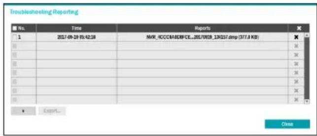
- Troubleshooting Reporting: When there is a problem with NVR system, generate reports for troubleshooting.
Date/Time
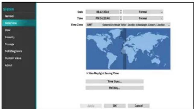
- Date: Used to change the system's date setting.
- Time: Used to change the system's time setting.
- Date Format/Time Format: Used to change the system's date and time formats.
- Time Zone: Used to designate the system's time zone.

Refer to the map displayed on the screen and change the time zone using the mouse or the arrow buttons.
- Use Daylight Saving Time: Enables DST correction.
- Time Sync.: Select a time server for the system to synchronize with.
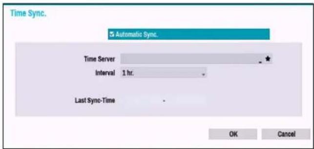
1 Select Automatic Sync.
2 Enter the Time Server's IP address or domain name or select ★ and then choose a server from the list of registered time servers.
3 Specify the server synchronization Interval.
4 Select OK to apply and exit.

- If you have configured the DNS Server setting under Network - WAN, you can enter the time server's domain name instead of its IP address.
- Holiday: Designate holidays. On specified holidays, recording takes place according to the holiday recording schedule specified under Record Schedule.
1 Select the + button at the bottom of the window.
2 Select a date.
3 Select OK to apply and exit.
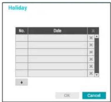

Select the icon to delete the existing holiday date.
User
Use this option to register users and assign permissions.
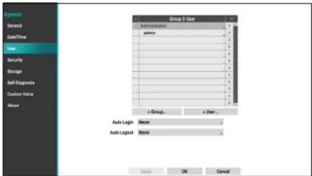
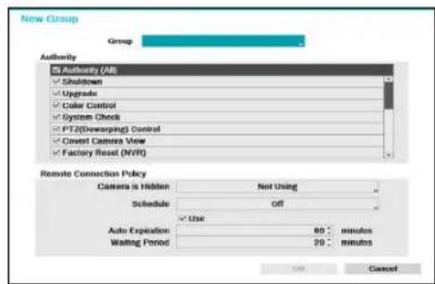
1 Select + Group and enter a group name. A group name can be up to 15 characters in length.
2 Specify the group's permission settings. For more information on permission settings, refer to the Group Permissions on page 34.
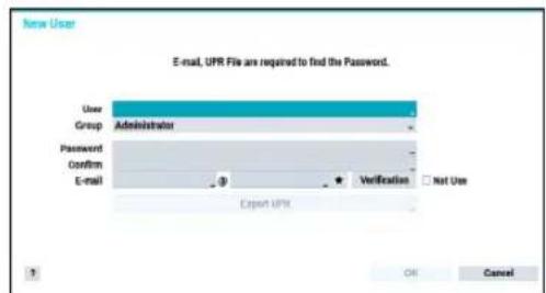
3 Select + User and then enter a user name.
Part 2 - Configuration
4 Select a group for the user and then enter a password. The password can be up to 16 characters in length and may include letters, symbols, and numbers. The e-mail address will be used as information on password verification.
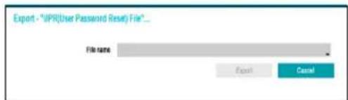
5 Select the Export button to create the UPR(User Password Reset) file. The UPR file can be used to finding a password offline. Select the location to save the UPR file and enter the file name.
6 Select OK.
7 Configure Auto Login and Auto Logout settings.
8 Select Apply or OK to exit.

- Group names, user names, passwords and email can be entered using the virtual keyboard. For more information on using the virtual keyboard, refer to the Text Input via Virtual Keyboard on page 30
•To delete a registered user or group, select the icon on the right of the corresponding user/group. Group Administrator and User admin cannot be deleted.
- Select the icon next to Group & User on the top of the screen to delete all groups and users except Group Administrator and User admin simultaneously.
- A password entry is required to edit existing groups and users.
- Group Administrator's permissions cannot be changed.
- With the User admin account, only the password can be changed.
- When the system starts up, it will automatically log into the account designated under Auto Login.
•The system will automatically log out of the account if the duration of inactivity specified under Auto Logout.
Group Permissions
| System Shutdown | May shutdown the system from the system menu. | |
| Upgrade | May upgrade the system from the system menu (System Setup). | |
| Color Control | May adjust each camera's brightness, contrast, saturation, and hue settings. | |
| System Check | May view System Check results. | |
| PTZ(Dewarping) Control | May control PTZ and Dewarping cameras. | |
| Covert Camera View | May access covert cameras in Live and Search modes. | |
| Factory Reset (NVR) | May reset the NVR to all its initial factory settings. | |
| Search Clip Copy | The user who has permission for Clip Copy can perform Clip Copy. If the user does not have permission, Clip Copy is not allowed but only search is allowed. | |
| Setup | Camera Setup | May configure camera settings. |
| System Time Change | May change the system's date and time settings. | |
| Data Clear | May clear data stored in the system. | |
| PTZ Setup | May configure PTZ settings. | |
| Covert Camera Setup | May configure convert camera settings. | |
| Record Setup | May configure recording settings. | |
| Self-Diagnosis | May configure the NVR self-diagnostic settings. | |
| Setup Import | May import previously saved NVR settings. | |
| Setup Export | May export current NVR settings. | |
Remote Connection Policy
| Camera Is Hidden | Select camera channels to hide on the screen when connecting remotely. | |
| Schedule | Select Schedule On and then configure the days of the week and remote connection interval. If not selecting Schedule On, remote connection is allowed regardless of scheduled intervals.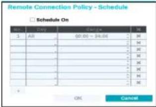 | |
| Use | Auto Expiration | Select Enable to set whether the auto-expiration period works. You can set the retention time when connecting to the NVR from a remote location. |
| Waiting Period | Select the limit time for access after automatic expiration. | |
Security
Use this option to configure security settings.
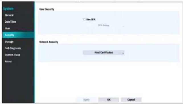
Use 2FA
Two-factor authentication (2FA) is a method of confirming a user's claimed identity by utilizing a combination of two different components.
In other words, it is a method of authenticating the registered mobile devices such as mobile phones and smartphones on NVR for security when proceeding settings, search and upgrade.
When you click Use 2FA and 2FA Setup buttons, the following window will appear (Registered means the time when the mobile device was registered).
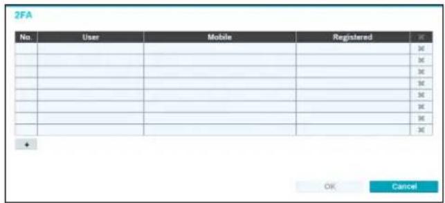
If you click the + button at the bottom of the table, the following message will appear and you can register the 2FA device.
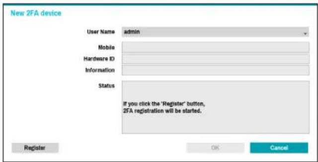

- 2FA device registration is supported only via IDIS Mobile app.
- Only the administrator account user can configure this option.
•The maximum number of device that can be registered is 16.
When the mobile device registration is complete, the following message will appear. Click Disable 2FA at the bottom left corner of the screen to deactivate 2FA function via the email of an administrator user account.
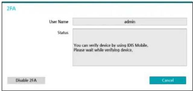
To use email authentication, the FEN setup must be configured. To use UPR function, the UPR file must be saved in advance.
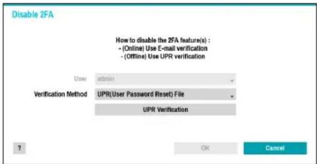

For more information on saving the UPR file, refer to User on page 33.
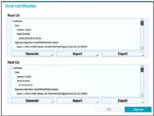
Network Security (Host Certificates)
This is the certificate management menu for network security access. It supports checking the product certificate information, creating the new certificate, exporting and importing certificates.
Storage
Use this option to configure storage settings.
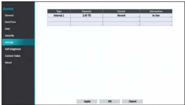
- Type: Indicates the type of the installed disk.
• Capacity: Indicates the disk's capacity.
- Format: If the disk has been formatted, indicates either Record or Not Using. If you have connected an unformatted storage device, the Use As value will be indicated as Not Formatted.
- Information: Indicates if the disk is being used for recording purposes. Disks that were used in different systems will show up as Other. Select Information to check the saved data's time information or select Delete to erase the data.

- Select Format to prepare the disk as a storage for data recording.
- Disks formatted with Use As set to Not Using will not be used for data recording.
•This NVR supports SATA2 HDDs.
Self-Diagnosis
Use this option to configure self-diagnostic settings.

This feature is also supported when connected to the NVR from a remote program.
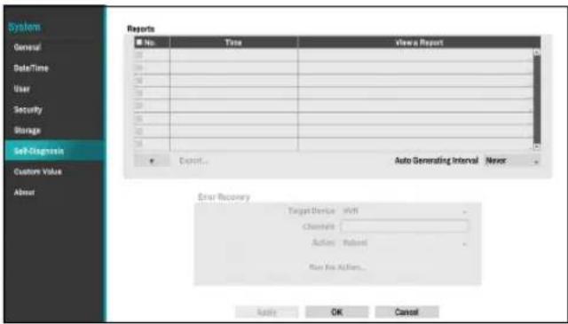
- Reports
- No.: Selects which reports to export.
– Time: Displays when you started the self-diagnosis.
- View a Report: Briefly displays whether the report is "Good" or "Bad".
- : Click the + icon at the bottom left corner of the screen to run the self-diagnosis.
- Export: Saves the Saves the reports to a storage device (USB port), by converting them to HTML format. You can export more than one report at a time by selecting multiple reports.
- Set up Auto Generating Interval and Check IP Duplicate.
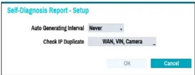
– Auto Generating Interval: Set the interval to automatically generate self-diagnosis report.
- Check IP Duplicate: Check if there are IP address conflicts of WAN, VIN, camera.

• These settings can be periodically checked for IP duplication, but Camera IP duplication checks have a long verification cycle, so you can run a self-diagnosis to check the results immediately.
- Check IP duplicate function can only be checked on the VIN network.

•The reports are stored in up to 24 files. If you have configured Auto Generating Interval as one-day period, only the the reports from the last 24 days can be viewed.
- If the NVR is turned off, the reports will automatically turn off.
•The reports are organized by recent date and time.
- FailOver: When a problem is detected on the target device, click the Run the failover button to resolve the problem.
- Target Device.: Selects which device to run the failover.
- Channels: Select the camera channel if a camera is set to the target device.
- Action: Select the type of action to run the failover.
- Run the failover: Click the Run the failover button when a fail is detected on the target device to resolve the problem.

Once Run the failover have made to the camera, the camera will reboot automatically.
![Self-Diagnosis Report - 2012-01-14 07:32:39 System Information: Device Name : NVR_WAN_6 Time : 2022-01-14 07:32:39 SW Version : 8.2.8 DQA.AJW Camera Count : 4 Internal PoE : 4 Pst ✓ 1. System 2. Network[D]- WAN △ 3. Network[D]- Video-in △ 4. Network[D]- FEN 5. Device Health Status 6. Storage Status 7. Camera Status Close](/content/2026/05/1015987/images/edc616c5af5c3cc09271b6e3198d9cbc47c80949427144ba1a22edea93c29377.jpg)
Once you have run failover on the camera, the camera will reboot automatically. By selecting System, Network, Device Health Status, Storage Status or Camera Status, you can see the brief results of the self-diagnosis for the target device.

The NVR self-diagnostic report can only be viewed in text form.
This feature is also supported when connected to the NVR from a remote program.
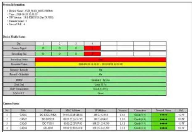
We recommend clicking the Export button at the bottom of the list, which allows you to view the reports on a PC web browser. We also recommend scanning the self-diagnostic report on a remote program, which allows you to view the reports in HTML format as shown below.
Custom Value
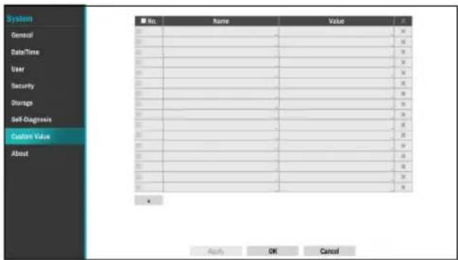
- Name: Set the name of system properties to be included in a JSON file on HTTP notifications.
- Value: Set the value of system properties to be included in a JSON file on HTTP notifications.
About
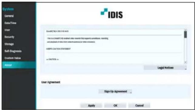
- User Agreement: User agreement for the use of the FEN service. If you agree, we collect device information such as IP address, port and router information to the FEN server.
Camera Setup
Refer to the Menu Use on page 29 for basic information on using the Setup menus.
Registration
You can register cameras at remote locales. By selecting a number from the list, you can move the camera up or down the list using the mouse wheel to reorder its position. The remaining cameras will move down the list automatically.
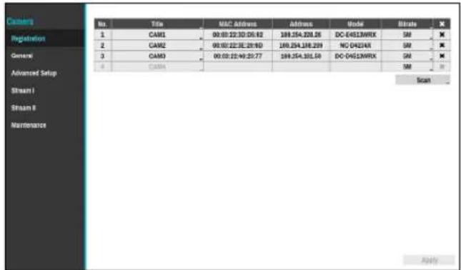
• Title: Edit the camera's name.
- MAC Address: Displays the camera's MAC address registered to the NVR.
- Address: Displays the camera's IP address registered to the NVR.
- Model: Indicates the camera's model.
- Bitrate: Changes the bitrate allocated to the channel.
- Scan: Select to scan and register the device connected to the NVR.

This feature is supported only when connected to the NVR from a remote program.
Device Scan
Scan the device under Registration - Scan.
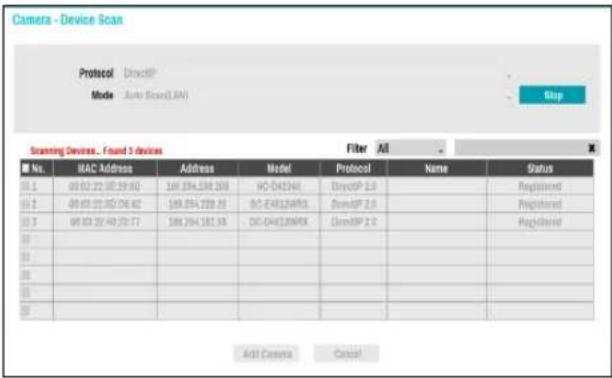
- Protocol: Select the protocol you wish to search for that was used by the camera (or encoder).
• Even if the network device uses a protocol supported by the NVR, the device itself may not be visible for scanning and registration by the NVR. For more information about supported network devices and models, contact your retailer.
•The supported scan modes may vary depending on protocol selected.
• Mode: Select the scan mode.
- Auto Scan(LAN): Lists any cameras in a LAN environment. If Auto scan (LAN) fails to recognize the camera, try using IP Address scan instead.
- IP Address: Enter the IP address of a camera. The NVR scans for the camera that matches the specified address. If you enter an IP address range, the NVR scans for cameras falling under the specified address range. By specifying an IP address, you can also specify which port to use with the Remote Admin feature. It is recommended that you do not network the camera via DHCP (Dynamic Host Configuration Protocol). If the camera is networked via DHCP, the camera may not be connected properly depending on changes in the external network environment.

If Auto Scan (LAN) fails to recognize a camera, try using the IP Address scan instead.
- Filter: Enter a keyword in the MAC Address / Address / Model / Name / Status fields for the selected camera. This allows the user to scan this camera easily.

- When configuring a port, the device may fail to scan if the port selected for the NVR and the port selected for the camera differ. In this case, you must register the camera to change its IP address.
- The device to be registered must have different IP addresses. Otherwise, the connection may fail.
- No.: Select the registered camera number and click the Add Camera button to register the camera.
- MAC Address: Displays the scanned camera's MAC address.
- Address: Displays the scanned camera's IP address.
• Model: Indicates the camera model.
- Protocol: Indicates the scanned camera's protocol.
- Name: Displays the scanned camera's IP name.
- Status: The "Registered" indicates the camera is registered to the NVR and "Not registered" indicates the camera is not registered to the NVR.
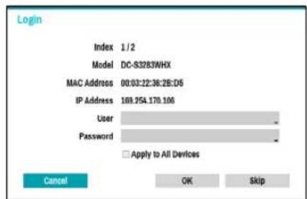
Login
If the password is set or you want to register third party cameras, registering a device requires an authorized user login.
1 Select the desired device from the list and click the Add Camera button, then the login window will appear.
2 Select a user, enter the password, and then select OK.
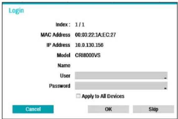

- By selecting Apply to All Devices, you can apply the same authentication information to all of the network devices in the list.
- When you select multiple network devices from the list and click the Add camera button, a window for the network device will appear. Select Skip to skip the authentication settings for the current network device and to display the Authentication window of the next network device.
- For IDIS cameras, a user and password may not be required.
Set Camera Password
For IDIS protocol cameras that support changing and finding the camera password, you must set the camera password at the time of initial camera registration. The email information is used to change and find the camera password.
1 Select the dedeivce from the list and click the Add Camera button, then Set Password window will appear.
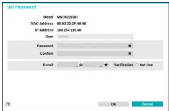

Only the camera that does not set password of the camera which supports the password setting function is displayed.
2 Enter the password and e-mail address, and then select OK.

- If you do not authenticate your email address, you may not be able to find your password unless you enter the correct information.
•FEN setup is required for authentication.
- By selecting Apply to All Devices, you can apply the same password and e-mail information to cameras that require password settings in the scan list.
- When you select multiple network devices from the list and click the Add camera button, a window for the network device will appear. Select Skip to skip the authentication settings for the current network device and to display the Authentication window of the next network device.
3 When the password is set, the login window will appear.
General
Enable/disable the covert view and rename cameras.
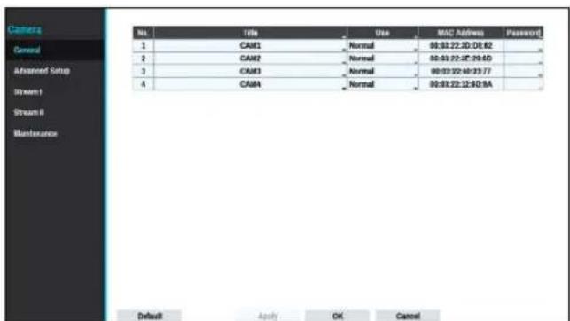
• Title: Edit the camera's name.
- Use: Set the camera as Normal, Covert 1, or Covert 2. Live images and video recordings from cameras that have been set as Covert 1 or Covert 2 will not be available to users who do not have covert camera access. Setting a camera as Covert 1 hides its images but does display OSD information about the camera. Setting a camera as Covert 2 hides its images as well as ODS information about the camera as if it has been deactivated completely.
Advanced Setup
Configure security and other advanced camera settings.
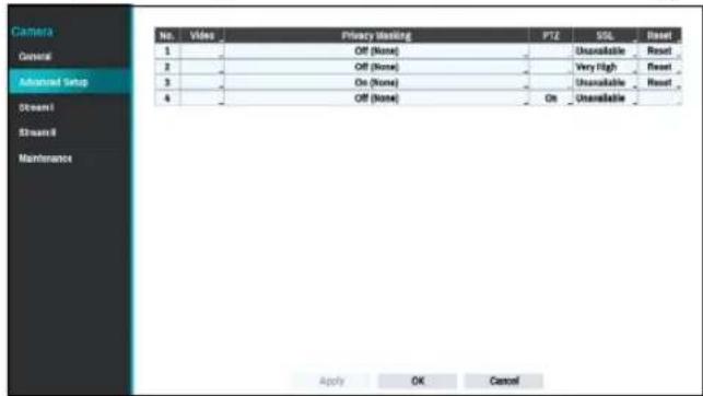
- Video: Adjust the camera image sensor settings such as white balance and exposure. Configuration options may differ depending on the camera model.
- Privacy Masking: Enable/disable and configure privacy masking for the camera.
- SSL: Set the camera's security level as Unavailable, Standard, High, or Very High. Standard, High and Very High settings apply SSL (Secure Sockets Layer) protection to the camera.

The more cameras security level is set to Very High, the more the device loads may occur due to the decoding of received data such as video and audio. This may cause the total recording performance to decrease and not work as you set it to. In this case, you must improve the load by lowering the security level or by lowering the recording bitrate.
- Reset: Resets the port or cameras.
- Factory Reset : Control the PoE Switch's port. This option is available when connecting to Video In/PoE port or using a DirectIP™ PoE Switch (optional). Select PoE Reset to reboot the camera. It is not supported by video encoders.
- Soft Reset : Reboots the camera.
- Factory Reset: Resets the NVR to all its initial factory settings. It is supported by DirectIP™ cameras only.
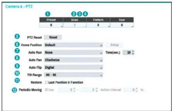

Numbers shown below Preset, Scan, Pattern, and Tour indicate the numbers of configured functions.
① Preset
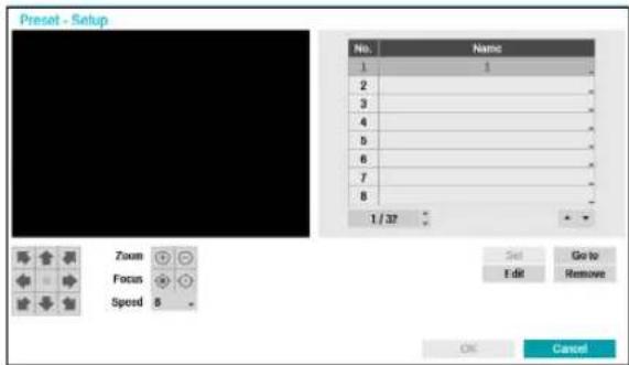
Use the buttons below to choose a preset position.
- Directional Buttons ( ); Used to tilt and pan the camera.
- Zoom (+): Zoom in and out.
- Focus (-): Adjust camera focus to far or near.
-
Speed: Specify the camera's panning and tilting speed.
-
Set: Choose a preset number and then enter a name. This saves the current preset under the specified preset number and name.
- Go to: Select a preset from the list and then click Go to to move the camera to the selected preset position.
- Edit: Used to change the selected preset's name.
- Remove: Used to remove the selected preset.
Part 2 - Configuration
② Scan
Used to set up a profile for moving the camera between two points. At least two presets must be available in order to use the scan feature.
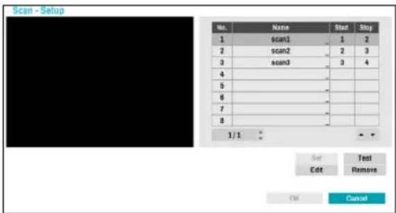
Set: Used to set up a scan profile.
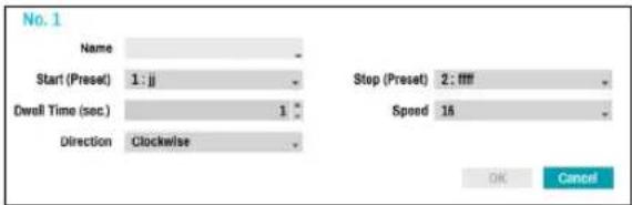
- Name: Enter a name for the scan profile.
- Start/Stop: Specify which presets to use as start and stop points.
- Dwell Time (sec.): Specify how long the camera will dwell at start and stop positions.
- Speed/Direction: Specify scanning speed and direction.
- Test: Select a scan profile and then click Test to test it.
- Edit: Used to edit the selected scan profile.
- Remove: Used to remove the selected scan profile.
③ Pattern
Used to set up a pattern profile for the camera to follow along.
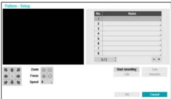
Start recording: Select a pattern number, enter a name for the pattern, and then click OK to save the pattern. Move the camera using directional, zoom, and focus buttons and then click Stop recording to save the pattern profile. You can record up to two minutes of movement.
- Directional Buttons (→ ↑ → ← → ↗ ↓ ↑):
Used to tilt and pan the camera.
- Zoom (+): Zoom in and out.
- Focus (●): Adjust camera focus to far or near.
-
Speed: Specify the camera's panning and tilting speed.
-
Test: Select a pattern profile and then click Test to test it.
- Edit: Used to edit the selected pattern profile.
- Remove: Used to remove the selected pattern profile.
④ Tour
Used to set up a tour profile of multiple functions in a designated sequence.
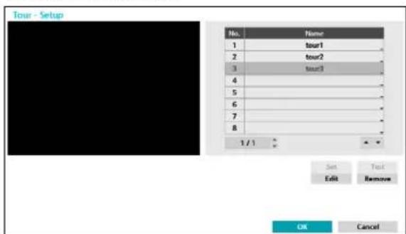
Set: Used to set up a tour profile.
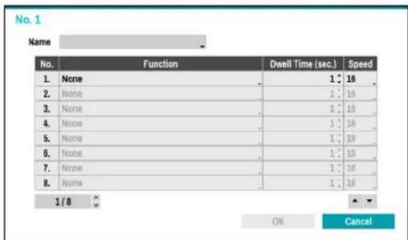
- Name: Enter a name for the tour profile.
- Function: Indicates the order of the function in the tour sequence.
- Dwell Time (sec.): Specify how long to perform the selected function for.
-
Speed: Specify the preset speed.
-
Test: Select a tour profile and then click Test to test it.
- Edit: Used to edit the selected tour profile.
- Remove: Used to remove the selected tour profile.

Select Apply after setting up a preset, scan, pattern, or tour profile to see images from the concerned camera on the left side of the screen. Selecting Apply or OK displays a popup screen that indicates whether the profile has been set up successfully.
⑤ PTZ Reset: Reboots the camera's panning / tilting and zoom settings.
⑥ Home Position: Specify the camera's home position.
- Default: Uses the factory-default position as the camera's home position.
- Custom: Uses the user-defined position as the home position.
- Select Set to change the home position.
⑦ Auto Run: Specify which action to take if the camera has not been controlled for the specified duration of time.
⑧ Auto Pan: Specify the camera's panning direction. When Auto Pan is selected from a remote program, the camera pans in the direction selected here.
⑨ Auto Flip: Automatically flips the image when the camera tilts past 90^ to prevent the objects from appearing upside down.
- Digital: Flips the image left to right or top to bottom.
- Mechanical: Automatically pans or tilts the camera.
• Off: Disables Auto Flip.
⑩ Tilt-Range: Specify the camera's tilting range.
⑪ Restore: Specify whether to restore the camera to its last position or function. Enabling this option restores the camera to its last position or function after being restarted.
⑫ Periodic Moving: Operate the PTZ camera at each operation cycle for the specified schedule period.
Privacy Masking Options
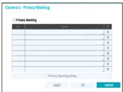
Select Name to rename the privacy masking area. Select the ☒ icon to delete the existing privacy masking area.
Select Privacy Masking Setup to display additional privacy masking area options. You can drag on the area with the mouse to resize it or add up to 16 different areas.
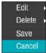
- Edit: Rename the selected privacy masking area.
- Delete: Delete the selected privacy masking area.
- Save: Save the changes and exit the privacy masking area options screen.
- Cancel: Exit the privacy masking area options screen without saving the changes.
Image Sensor Options
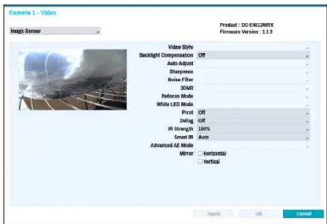
- Product, Firmware Version: Displays the camera model name and firmware version.
• Video Style: Select TV1 Color or PC Color.
- Backlight Compensation: Enable/disable Backlight Compensation. If enabled, objects are exposed brighter in backlit situations.
- Auto Adjust: Selecting Auto allows the system to assess the lighting conditions and adjust the setting automatically. Selecting Manual allows the user to adjust the setting manually.
- Sharpness: Adjust the sharpness level. Adjust the contours to make the images look sharper. Increasing the value raises the sharpness level, but using too high a value can result in unwanted noise.
- Noise Filter: Select the noise filter level. Noise filter can reduce the noise in images taken under low-lighting conditions. Increasing the value reduces the noise, but using too high a value can result in blurry images.
- 3DNR : Enable/disable 3DNR (3D Noise Removal). 3DNR reduces background noise in images taken under low-lighting conditions. 3DNR does not produce blurry images like Noise Filter but can result in ghosting.
- Refocus Mode : Readjust the focus of the camera when changing daytime to nighttime or nighttime to daytime.
- On/off: Enable/disable Refocus Mode.
– DN Mode Shift: When image of the camera is switched to daytime or nighttime, the focus of the camera will be adjusted.
- IR Adaptive Shift: Readjust the focus of the camera when IR is detected by the camera.
- White LED Mode: Clicking on/off enables or disables White LED lighting when motion is detected by the PIR sensor. Also clicking auto allows the system to enable/disable White LED mode automatically.
- Pivot: Enable this option and choose the direction of the pivot. You can turn the image by 90 degree in the clockwise or counterclockwise direction. This feature is particularly effective when monitoring hallways, passages, and other confined spaces.
- Defog: Disables or enables the Defog feature. When it is enabled, image with a fog is adjusted.
- IR Strength: Adjust the IR LED's brightness level. Select a brightness level manually between 0% (darkest) and 100% (brightest). Selecting Auto(Smart IR) allows the system to control the IR LED's brightness level automatically.
- Smart IR: Help solve the problem of infrared LEDs whiting out images, such as people's faces, when they are too close to the IR LEDs of a night vision camera. In this case, the image is adjusted through AE control.
- Advanced AE Mode: Select desired setup mode between Normal and Number-Identification. In Number-Identification mode, when a certain area of images is too bright due to backlight under low lighting conditions and it causes the other area to be too dark, this function provides the other area of images brightly and clearly by blocking the backlight in the certain area. Dark parking lot entrances and gas station entrances at night, for example (Local Exposure compensates for the bright light coming from incoming vehicle headlights and makes it possible to see the license plates). When setting to the Number-Identification mode, some option settings will be adjusted automatically, and you cannot change them as long as the Setup Mode is not changed.
- Mirror: Select Horizontal or Vertical to flip the image horizontally and/or vertically.

Select Apply after setting up a camera to see images from the concerned camera on the left side of the screen. Selecting Apply or OK displays a popup screen that indicates whether the camera has been set up successfully or not.
White Balance Options
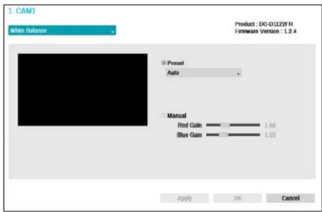
- Preset: Use preconfigured white balance settings.
- Auto: Allow the system to adjust the white balance automatically. The system will assess the lighting conditions and adjust the white balance automatically.
- Incandescent - Fluorescent Cold: Select a lighting type to apply the appropriate white balance.
- Manual: Adjust the white balance manually. Adjust Red and Blue gain values. Greater the value, greater the intensity of the corresponding color.

Select Apply after setting up a camera to see images from the concerned camera on the left side of the screen. Selecting Apply or OK displays a popup screen that indicates whether the camera has been set up successfully or not.
Exposure Options
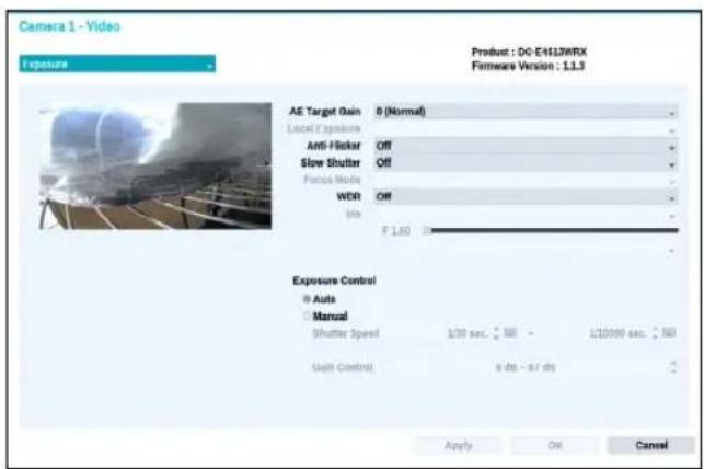
- AE Target Gain: Specify exposure compensation's target gain. Exposure is compensated automatically based on the specified target gain. Higher the gain, brighter the images.
- Local Exposure: Activate Local Exposure. Use Local Exposure on images that appear too dark due to backlighting conditions and on images containing over-exposed sections. Greater the value, clearer the image. e.g.) Dark parking lot entrances and gas station entrances at night (Local Exposure compensates for the bright light coming from incoming vehicle headlights and makes it possible to see the license plates).
- Anti-Flicker: If the lights in the area where the camera is located use alternating current, specify the frequency of the lights to minimize flickering. Matching the frequencies can eliminate flickering completely. (NTSC: 60Hz, PAL: 50Hz).
- Slow Shutter: Activate Slow Shutter. The slow shutter mode functions only under low lighting conditions. When the slow shutter mode is enabled, images are displayed bright even under the low-lighting conditions. There may be a difference in the way it functions depending on the camera model. See the camera user's manual for details.
- Focus Mode: Used to change the focus movement format as Auto/Manual/Semi-Automatic. It may not be supported depending on the device.
- WDR: Disables or enables the WDR (Wide Dynamic Range). When the very dark and very bright areas exist simultaneously on the screen, WDR allows you to recognize the both areas.
- IRIS: Depending on the camera type, the user can select DC-IRIS or P-IRIS.
- DC IRIS
- OFF: Select this if a manual IRIS lens is mounted on the camera.
- DC-IRIS (Auto): Select THIS IF A DC-type auto IRIS lens is mounted.
- P-IRIS
- P-IRIS (Auto): The system will assess the lighting conditions and adjust the openness of IRIS automatically.
- P-IRIS (Fix): Use the slider to select the desired openness of IRIS. Select the most suitable value for the lighting conditions in the area where the camera is located.
- Exposure Control: Adjust Shutter Speed and Gain. This option is available only when Anti-Flicker and Slow Shutter are both set to Off.
- Auto: The system will assess the lighting conditions and adjust the shutter speed and gain automatically.
- Manual: Use the slider to select the desired shutter speed and gain. Select the most suitable minimum and maximum shutter speeds and gains for the lighting conditions in the area where the camera is located. (1/30 to 1/8000)

Select Apply after setting up a camera to see images from the concerned camera on the left side of the screen. Selecting Apply or OK displays a popup screen that indicates whether the camera has been set up successfully or not.
Day & Night Options
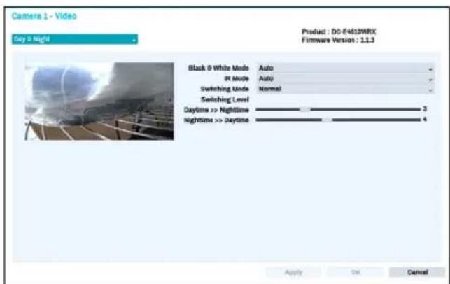
- Black & White Mode: Display the images in grayscale for greater clarity in low-lighting conditions.
- On/Off: Enable/disable Black & White Mode.
- Auto: Allow the system to enable/disable Black & White Mode automatically.
- Schedule: Set up the Black & White Mode schedule. Black & White Mode is disabled for all days and times that are designated as Daytime in the schedule and is enabled at all other times.
- IR Mode: IR Mode blocks out the infrared spectrum. You can ensure clear images at all times by blocking out the infrared spectrum in high-lighting conditions and allowing the infrared spectrum to pass through in low-lighting conditions.
- Daytime Mode/Nighttime Mode: Enable/disable IR Mode.
- Auto: Allow the system to enable/disable IR Mode automatically.
- Schedule: Set up the IR Mode schedule. IR Mode is disabled for all days and times that are designated as Daytime in the schedule and is enabled at all other times.

Some camera models may not support the Schedule function.
- Switching Mode: Changes the switching mode of daytime and nighttime. In normal mode, daytime/nighttime is switched through the amount of light received by the ambient light sensor. In advanced mode, it is switched through the amount of light and the analysis of the camera video.
- Switching Level: Controls the changing time of daytime / nighttime mode, depending on the Switching Level. The higher the value is, day / nighttime mode is changed under high-lighting conditions. Also the lower the value is, day / nighttime mode is changed under low-lighting conditions.
View Options
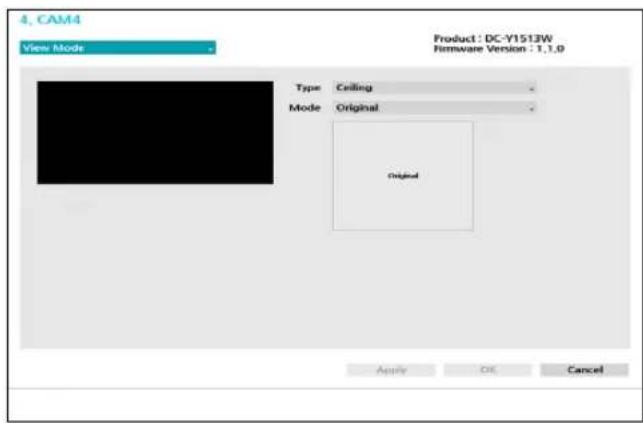
• Type: Selects the camera view.
- Mode: Selects the screen layout in live mode.

- Dewarping feature is not supported when mode is set to the original.
- When changing the view mode, the resolution will be applied automatically.
Miscellaneous
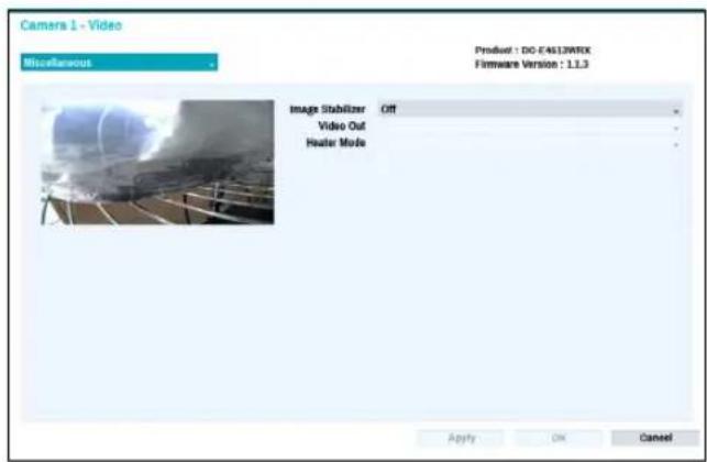
- Image Stabilizer: Activate Image Stabilizer. The Image Stabilizer reduces blurring caused by camera shake that results from external conditions such as the wind.
- Video Out: Select NTSC or PAL as the method of camera analog video output.
- Heater Mode: Set whether to use the heater. If On, the heater will operate if the camera's temperature is lower than the heater operating temperature. If Off, the heater will not operate regardless of temperature.
Stream I
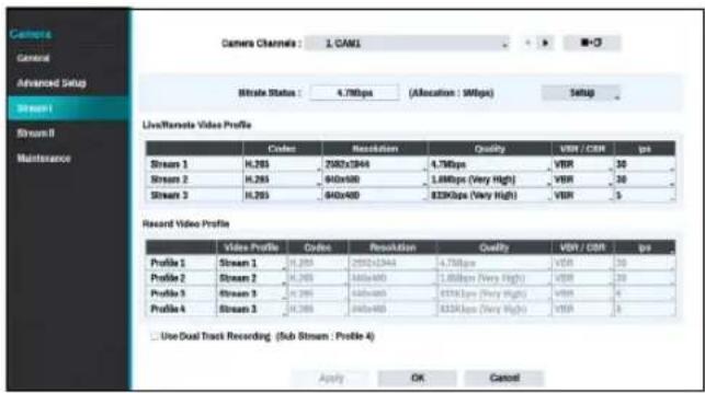
Configure the camera's live and recording resolution, codec, picture quality, transfer speed, and ips speed settings.
- Camera Channels: It's possible to configure a unique video profile for each camera.
- Bitrate Status: Display the highest value of stream. Click the Setup button to change the allocation for each channel. For more information on bitrate, refer to Camera View Buttons on page 16.
- ■→□ : Apply the video profile settings of the camera selected under Camera Channel to a different camera.
- Live/Remote Video Profile: Check the current Live video picture quality and edit remote video profile settings.
- Record Video Profile: Set up 4 recording quality profiles.
- Video Profile: Select Stream 1, Stream 2, Stream 3, or Custom (available from Record Video Profile only).
- Codec: Supports H.264 and H.265.
- Resolution: Select a resolution supported by the camera. Maximum available resolution is chosen automatically based on the selected video profile.
- Quality: Assign different quality settings to different cameras.
- VBR/CBR: Select VBR or CBR. Transmitted data size varies depending on the amount of movements in the images with VBR but is fixed with CBR.
- ips: Select a value between 1 and 30. Maximum ips is determined automatically based on the selected video profile.
- Bitrate: Displays the bitrate value of each stream.

The bitrate is determined by the codec, resolution, quality, and IPS settings. Settings beyond the channel's assigned bitrate are limited.
Part 2 - Configuration
- Use Dual Track Recording: Set to record with the video profile value (main stream) set in the schedule and record with the profile 4 value (sub stream) at the same time.

- It displays as below when recording on a network video recorder.
- The video profile (main stream) set in the schedule is displayed. If the resolution exceeds 8M in total, Profile 4 (sub-stream) is displayed.
- If the total resolution exceeds 8M in 1+5, 1+7 screen layout, Profile 4 (sub-stream) is displayed.
- If the total resolution does not exceed 8M, it is displayed as follows. If the channel is larger than 3x3 size on the screen layout, the video profile (main stream) is displayed first but otherwise the profile 4 (sub stream) is displayed.
- This function is supported only for cameras supporting dual recording function.
Stream II
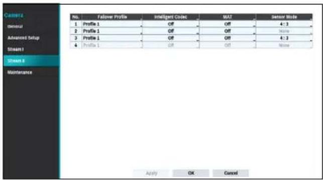
Configure the camera's failover profile, intelligent codec and MAT settings.
- Failover Profile: Select a video profile for the smart failover recording.
- Intelligent Codec: Lower bitrate by using the intelligent codec.

• Some camera models may not support the Intelligent Codec function.
- MAT Setup : Select the MAP Setup option to use the MAT (Motion Adaptive Transmission) function during video transmission and recording.

- When the MAT (Motion Adaptive Transmission) function is active, the associated VA device may not work properly.
- It is recommended that you do not use the MAT function of the associated camera to increase the accuracy of the image analysis.
- Some camera models may not support the MAT function.
* MAT function(Motion Adaptive Transmission) reduces bandwidth overload and saves storage capacity by reducing the frame rate of the video during periods of inactivity. The user can select the period of sustained inactivity which triggers this function by adjusting Inactivity Period.
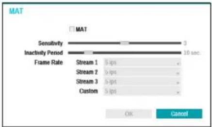
bar
| Metric | Value | | --------------- | ----- | | Sensitivity | 3 | | Inactivity Period| 10 | | Frame Rate | Stream 1, Stream 2, Stream 3, Custom | | | 5 ips | | | 5 ips | | | 5 ips | | | 5 ips |- Sensitivity: Set the motion detection sensitivity. Higher values will result in more sensitive motion detection.
- Inactivity Period : Set the Inactivity Period. If motion is not detected for the duration of time specified, video is transmitted and recorded using the frame rate designated below until movement is detected again.
- Sensor Mode: Set the camera resolution to 16:9, 4:3. Depending on the mode you have set, the resolution that can be set in the stream section changes.
Maintenance
When the USB search window appears, select the corresponding upgrade package from the storage device connected to the NVR's USB port. After selecting the upgrade package, select Apply to upgrade the camera. Camera settings can be imported or exported.
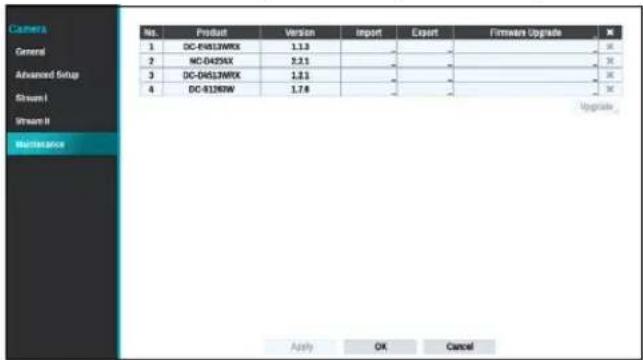

- If an upgrade attempt fails, an upgrade failure message will be displayed. Refer to Error Code Types in the installation manual for more details.
- The camera will reboot after the upgrade and then reconnect automatically.
Record Setup
Refer to the Menu Use on page 29 for basic information on using the Setup menus.
General
Configure general recording settings.
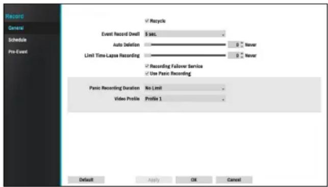
- Recycle: When the recording disks become full, the system overwrites existing data with new data, starting with the oldest first. If Recycle is disabled, recording will simply stop when the recording disks reach their maximum capacity.
- Event Record Dwell: If linked recording is designated as an event-triggered action, recording takes place for the duration specified under this setting.
- Auto Deletion: Configure this option to delete recording data automatically after the specified number of days has elapsed. Select between 1 day and 999 days.

To disable Auto Deletion, select Never. If enabled, recording data will be stored on the NVR for the specified number of days and then deleted automatically. Expired recording data are deleted automatically at midnight and will be deleted even if the system reboots or the Auto Deletion setting has been changed.
- Limit Time-Lapse Recording: You can store event recording data for longer. If you do not wish to use Limit Time-Lapse Recording, select Never. This function is activated when data has been stored for longer than as configured because the recording disk has sufficient capacity and saves new data by overwriting Time Lapse Recording data that are older than as specified under Recycle mode.

- If the recording stored on the disk is shorter than the duration specified under Limit Time-Lapse Recording, the older of Event Recording or Time Recording data is deleted first.
- The system's recording time may change depending on recording quality, resolution, motion, and other configurations made by the user. The duration specified under Limit Time-Lapse Recording may not be guaranteed in certain situations.
- Recording Failover Service: When the network error has recovered, images temporarily stored in the camera's buffer memory can be recorded to NVR.
- Use Panic Recording: Enable/disable Panic Recording.
- Panic Recording Duration: Disable Panic Recording automatically. Select between 5 mins and 1 hr. If you do not wish to disable the feature automatically, select No Limit.
- Video Profile: Select a recording profile value for Panic Recording.
Schedule
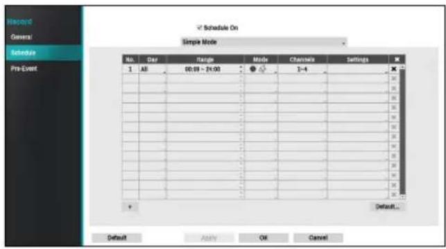
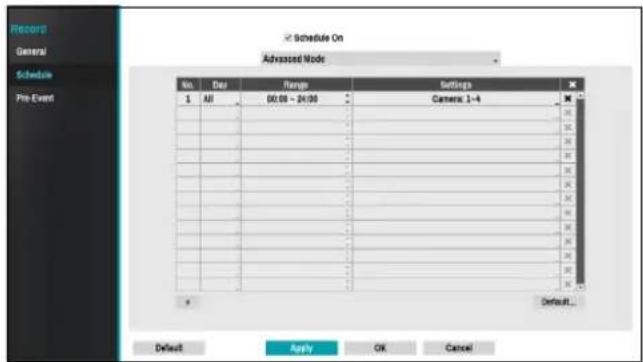
Disabling Schedule On suspends schedule recording regardless of the schedule and displays the 🔒 icon on the upper left corner of each camera screen. Pressing the Panic Record button displays the 🔒 icon and commences panic recording.
Set Record Schedule mode as Simple Mode or Advanced Mode. Advanced Mode allows you to configure a unique recording schedule for each event. Select the ✗ icon to delete a schedule.

- Changing the recording schedule mode suspends all active event-linked actions.
- Select the + button on the bottom left of the screen to add a schedule. Select Day to specify the Day setting or select All. Select Scope to specify the time frame.
Simple Mode Options
- Mode: Select No Record, Time, Event, or Time & Event.
| No Record | Unless the Panic Record button is pressed, no recording will take place during the scheduled time frames on the scheduled days. |
| Time | Theicon appears on the upper left corner of the screen. Theicon appears at scheduled times to indicate recording is in progress. |
| Event | Theicon appears on the upper left corner of the screen. Theicon appears when the specified event occurs to indicate recording is in progress. If Pre-Event is enabled, theandicons appear when recording is not in progress, or theandicons appear when an event occurs and recording is in progress. If Pre-Event is enabled, theandicons appear when recording is not in progress, or theandicons appear when an event occurs and recording is in progress. |
| Time & Event | Theicon appears on the upper left corner of the screen and recording commences as per the video profile selected for time under Setup. When an event occurs, the icon changes intoicon and recording commences as per the video profile selected for events under Setup. |
- Channel: Select which cameras to apply the schedule to.
- Settings: Select to configure default recording profile values for Time Lapse and Event Recording modes.
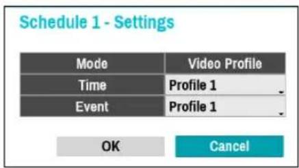
Part 2 - Configuration
If a camera supporting the Dual Track Recording function (Main and Sub stream) is in use, the following icon will be displayed.
 | Recording both mainstream and substream |
 | Recording one of the mainstream and substream |
| [HZY0] | Failed to record both mainstream and substream |
Advanced Mode Options
Select to configure event types and video profiles.
- Type: Event-specific and time recording icons are as follows:
 | Time Lapse (Time) | [BAX3] | Trip Zone |
| [KBXT] | Motion Detection | [WDG7] | Tampering |
 | Video Loss Record Fail | ||
| [7SX5] | PIR Auto Trac(ZZZW) | ||
- Video Profile: Configure the profile to use for recording.
- Dwell: Specify how long to record for after a corresponding event occurs.

• Upper-tier schedule's settings apply to unconfigured channels.
- If multiple events take place on a specific channel and different Video Profile and Dwell Time settings apply, highest settings apply to all event-linked recordings.
Pre-Event
When an event occurs, enabling this option includes the specified duration prior to the event in the event-triggered recording.
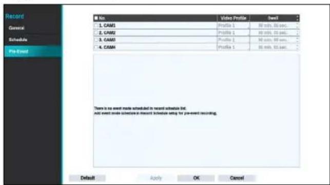
- No.: Select which cameras to apply Pre-Event to.
• Video Profile: Select a video profile for the recording. - Dwell: Specify the duration of pre-event recording data.

- If no event mode schedule exists in the schedule, a warning message prompting you to add an event mode schedule will be displayed.
- The warning message will appear even in Time & Event mode.
Event Setup
Refer to the Menu Use on page 29 for basic information on using the Setup menus.
System\_Event
Use this option to configure system event settings.
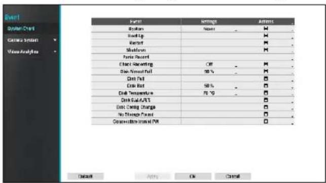
- Settings: Configure when and what the system should monitor for.
- Actions: Configure notification (email, LAN1 through 5, push, HTTP, alert window) settings.
Monitoring Options
| System | Define monitoring times. If self-diagnosis is not performed on a regular basis, the system will assume an error. |
| Bootup, Restart, Shutdown | Define bootup, restart and shutdown actions. |
| Panic Record | Define panic recording actions. |
| Check Recording | The system will assume an error if the system has been scheduled to record normally but recording does not take place during scheduled intervals. Select Schedule On and then configure the days of the week, times, and monitoring interval.Select the button on the bottom left of the screen to add a schedule. Select icon to delete the schedule. Select Schedule On and then configure the days of the week, times, and monitoring interval.Select the button on the bottom left of the screen to add a schedule. Select icon to delete the schedule.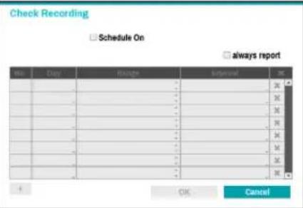 |
| Disk Almost Full | Generates an event if the disk reaches the specified capacity (80% to 99%). |
| Disk Full | Generates an event when all disks reach their maximum capacity. |
| Disk Bad | Generates an event when the specified percentage of the disk becomes damaged. Set to between 10% and 90% in 10% intervals. |
| Disk Temperature | Specify the threshold temperature.Once any disk reaches this threshold, the system will issue an alert. |
| DiskS.M.A.R.T. | Monitors disks that support S.M.A.R.T. and notifies the user if a disk error is detected. |
| Disk Config Change | It will be highlighted when the NVR reboots after the hard disk drive has been replaced. |
| No Storage Found | It will be highlighted when no hard disk drive has been connected. |
| Consecutive Invalid PW | It will be highlighted when login fails by entering a wrong password for consecutive attempts. |

- For system events, only an e-mail notification of actions can be selected.
- In order to use the Notify(Callback) feature, the NVR must be registered to the remote program on the receiving PC's end.
Camera System
A list of events that occur in the camera except for video analysis.
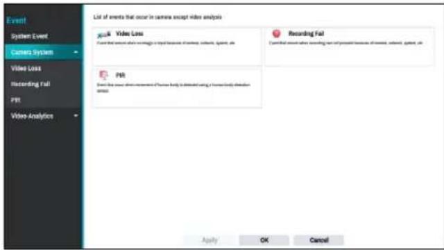
Camera System\_Video Loss
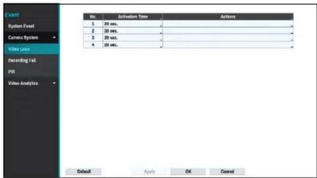
- Activation Time: Specify how long video loss has to last in order for it to be considered as an event. When the video loss is not detected for the specified duration of time, it will not be considered as an event.
-
Actions: Specify which actions to take when a Video Loss event occurs.
-
Record: Specify which cameras to begin linked recording on when an event occurs. If the schedule is set to Event or Time & Event mode, the selected cameras will begin linked recording when an event occurs.
- Notify: Configure to be notified of events by Mail, LAN1 through 5, Push, HTTP, and/or Alert Window.
- PTZ: Moves the PTZ camera to a specific preset position when an event occurs.
- Event Monitoring: Selects the cameras to monitor when an event occurs.

In order to use the Callback feature, the NVR must be registered on the remote program.
Camera System\_Recording Fail
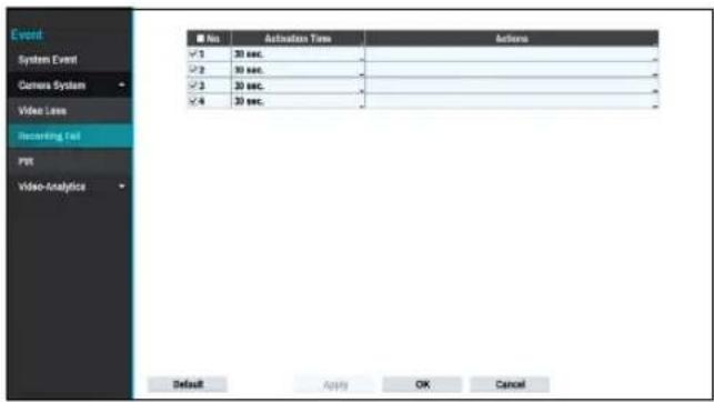
- Activation Time: Specify how long recording fail has to last in order for it to be considered as an event. When the recording fail is not detected for the
- an event.
- Actions: Specify which actions to take when a Recording Fail event occurs.
- Record: Specify which cameras to begin linked recording on when an event occurs. If the schedule is set to Event or Time & Event mode, the selected cameras will begin linked recording when an event occurs.
- Notify: Configure to be notified of events by Mail, LAN1 through 5, Push, HTTP, and/or Alert Window.
- PTZ: Moves the PTZ camera to a specific preset position when an event occurs.
- Event Monitoring: Selects the cameras to monitor when an event occurs.

In order to use the Callback feature, the NVR must be registered on the remote program.
Camera System\_PIR
This event occurs when the PIR sensor mounted on the camera is used to sense motion. Since the PIR sensor detects the temperature of the human, it can detect motion even in dark places without light.
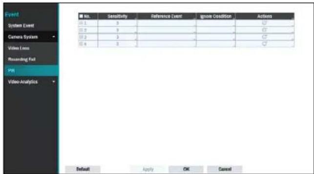
- No.: Select which cameras to apply PIR to.
- Sensitivity: Set sensitivity settings between 1 (Low) and 5 (High).
- Reference Event: Set condition for event to occur using the PIR sensor. A PIR event occurs when a motion occurs after an event set as a reference event has occurred. You can set Motion and Trip Zone as
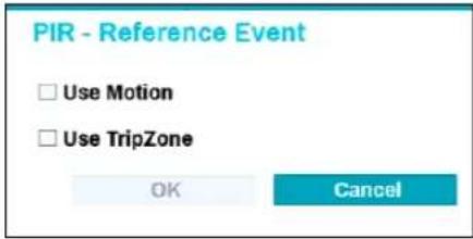
- Ignore Condition
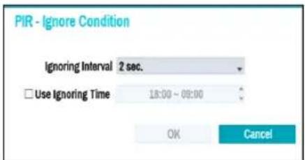
- Ignoring Interval: The system does not produce event log entries or remote notifications for events detected within a certain period of time after PIR events of the camera channels are detected. Set the value between 1 sec and 5 secs or choose Never.

Ignoring interval setting does not affect the motion detection recording.
- Use Ignoring Time: Select Time Setup to specify the PIR detection ignore time of camera channels. PIR detection will be disabled during the specified time frame.
- Actions: Specify which actions to take when a PIR event occurs.
- Record: Specify which cameras to begin linked recording on when an event occurs. If the schedule is set to Event or Time & Event mode, the selected cameras will begin linked recording when an event occurs.
- Notify: Configure to be notified of events by Mail, LAN1 through 5, Push, FTP, and/or Alert Window.
- PTZ: Moves the PTZ camera to a specific preset position when an event occurs.
- Event Monitoring: Selects the cameras to monitor when an event occurs.
Video-Analytics
Event lists that occur through video analysis include Motion, Tampering, PIR, TripZone, Face Detection and Auto Tracking events..
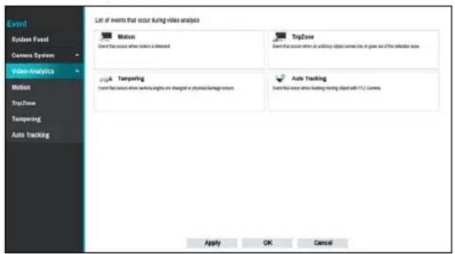
Video-Analytics\_Motion
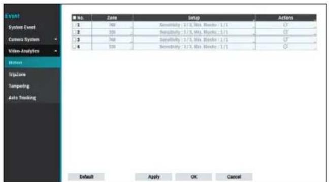
- No.: Select which cameras to apply Motion Detection to.
• Zone: Define the motion detection block.
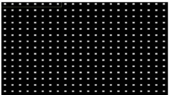
natural_image
Grid of white squares on a black background, no text or symbols presentUse the remote control's arrow buttons to move the block selection window up, down, left, and right. The selection window consists of 8 blocks per row. Select/deselect individual blocks using the Camera buttons. You can use the mouse to drag the zone and then select, clear, or reverse the selection.
From the zone selection screen, press the ← button on the remote control or right-click on the mouse to open up the Zone Setup menu.
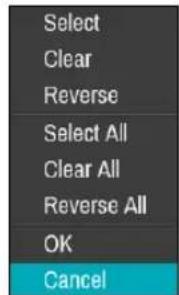
- Select: Confirm the block selection in the selection window.
- Clear: Clear the block selection in the selection window.
- Reverse: Clear the blocks selected within the selection window and select all unselected blocks within the selection window.
- Select All: Select all blocks.
– Clear All: Clear all block selections. - Reverse All: Clear all selected blocks within the screen and select all unselected blocks within the screen.
- OK: Save the changes and exit the menu.
-
Cancel: Exit the menu without saving the changes.
-
Setup
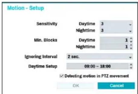
- Sensitivity: Set daytime and nighttime sensitivity settings between 1 (Low) and 5 (High).
- Min. Blocks: Motion needs to be detected in more than the specified number of blocks in order to trigger a Motion Detection event. You may select a value between 1 and the number of blocks selected under Zone for daytime and nighttime, each.
- Ignoring Interval: The system does not produce event log entries or remote notifications for motion detected within a certain period of time after the motion of the camera channels is detected. Set the value between 1 sec and 5 secs or choose Never.

Ignoring Interval does not affect motion detection recording.
Part 2 - Configuration
– Daytime Setup: Specify when daytime starts and ends. Adjust the time frame in 15-minute increments. Times outside the specified range will be assumed as nighttime by the system.
- Actions: Specify which actions to take when motion is detected.
- Record: Specify which cameras to begin linked recording on when an event occurs. If the schedule is set to Event or Time & Event mode, the selected cameras will begin linked recording when an event occurs.
- Alarm-Out: Designate event-triggered alarm-out channels (each for the NVR and camera) and beeps.
- Notify: Configure to be notified of events by Mail, LAN1 through 5, Push, HTTP, FTP, and/or Alert Window.
- PTZ: Moves the PTZ camera to a specific preset position when an event occurs.
- Event Monitoring: Selects the cameras to monitor when an event occurs.

In order to use the Callback feature, the NVR must be registered on the remote program.
- Condition: When a specific event occurs, you can set the condition that determines whether to operate motion according to the status of other events.
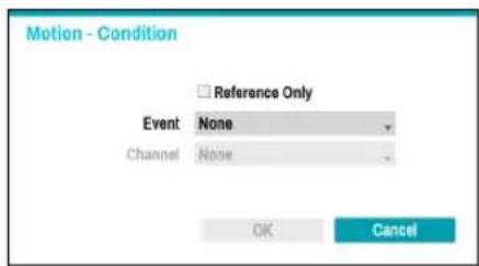
– Reference Only: Set the event to be the subject of a reference.
- Event: Set the reference event.
- Channel: Set the reference channel.
Video-Analytics\_Trip Zone
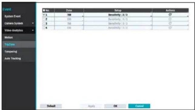
- No.: Select which cameras to apply Trip Zone to.
• Zone: Define the motion detection block.
natural_image
Grid of white squares on a black background with no text or symbolsUse the remote control's arrow buttons to move the block selection window up, down, left, and right. The selection window consists of 8 blocks per row. Select/deselect individual blocks using the Camera buttons. You can use the mouse to drag the zone and then select, clear, or reverse the selection.
From the zone selection screen, press the ← button on the remote control or right-click on the mouse to open up the Zone Setup menu.
| Select |
| Clear |
| Reverse |
| Select All |
| Clear All |
| Reverse All |
| Trip Direction ▶ |
| OK |
| Cancel |
- Select: Confirm the block selection in the selection window.
- Clear: Clear the block selection in the selection window.
- Reverse: Clear the blocks selected within the selection window and select all unselected blocks within the selection window.
- Select All: Select all blocks.
– Clear All: Clear all block selections. - Reverse All: Clear all selected blocks within the screen and select all unselected blocks within the screen.
- Trip Direction: Define in which direction the motion has to occur in order for it to be considered an event. Select In for movements from outside the selection area in or Out for movements from inside the selection area out.
- OK: Save the changes and exit the menu.
- Cancel: Exit the menu without saving the changes.
- Setup
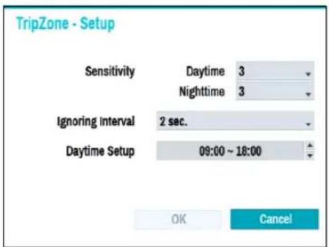
- Sensitivity: Set daytime and nighttime sensitivity settings between 1 (Low) and 5 (High).
- Ignoring Interval: The system does not produce event log entries or remote notifications for events detected within a certain period of time after Tripzone events of the camera channels are detected. Set a value between 1 sec and 5 secs or choose Never.
√ Trip Zone Ignoring Time does not affect Trip Zone recording.
– Daytime Setup: Specify when daytime starts and ends. Adjust the time frame in 15-minute increments. Times outside the specified range will be assumed as nighttime by the system.
- Actions: Specify which actions to take when Trip Zone is detected.
- Record: Specify which cameras to begin linked recording on when an event occurs. If the schedule is set to Event or Time & Event mode, the selected cameras will begin linked recording when an event occurs.
- Notify: Configure to be notified of events by Mail, LAN1 through 5, Push, FTP, and/or Alert Window.
- PTZ: Moves the PTZ camera to a specific preset position when an event occurs.
- Event Monitoring: Selects the cameras to monitor when an event occurs.
In order to use the Callback feature, the NVR must be registered on the remote program.
Video-Analytics\_Tampering
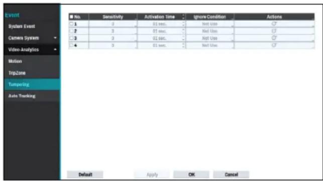
- No.: Select which cameras to apply Tampering to.
- Sensitivity: Set to between 1 (Low) and 5 (High).
- Activation Time: Specify how long tampering detection needs to last in order for it to be considered an event. Tampering detections that do not last for the specified duration of time will not be considered as events.
- Ignore Condition
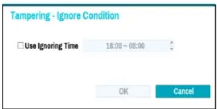
- Use Ignoring Time: Select Time Setup to specify the tampering detection ignore time of camera channels. Tampering detection will be disabled during the specified time frame.
- Actions: Specify which actions to take when Tampering is detected.
- Record: Specify which cameras to begin linked recording on when an event occurs. If the schedule is set to Event or Time & Event mode, the selected cameras will begin linked recording when an event occurs.
- Notify: Configure to be notified of events by Mail, LAN1 through 5, Push, and/or Alert Window.
- PTZ: Moves the PTZ camera to a specific preset position when an event occurs.
– Event Monitoring: Selects the cameras to monitor when an event occurs.

In order to use the Callback feature, the NVR must be registered on the remote program.
- Use Ignoring Time: Select Time Setup to specify the tampering detection ignore time. Tampering detection will be disabled during the specified time frame.
Video-Analytics\_Auto Tracking
When the PTZ camera detects a moving object, the camera operates the PTZ to track the moving object. Auto tracking event occurs simultaneously when the PTZ camera tracks an object.
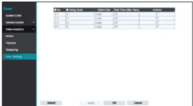
- No.: Select which cameras to apply Auto Tracking to.
- Using Zoom: When tracking an object, the PTZ zooms in the object.
- Object Size: Set the zoom level when using auto tracking. The larger the object size is set, the larger the object will be displayed on the screen.

This setting is enabled only when the Zoom function is on.
- Wait Time After Trace: After the object tracking is completed, the camera monitors the end position for a set period of time and then moves the PTZ to the initial position.

- If you do not set this function, the PTZ will not move to the initial position after auto tracking ends.
- Only some PTZ cameras support this event. Please contact the manufacturer for availability of this event.
- When setting the PTZ with an linked action in the Action tab, the camera where the event occurs cannot be set to PTZ linked action camera. For instance, when setting PTZ on the Auto Tracking-Actions(no.8) tab, you cannot set PTZ of no.8 camera.
- Actions: Specify which actions to take when Alarm-In is detected.
- Record: Specify which cameras to begin linked recording on when an event occurs. If the schedule is set to Event or Time & Event mode, the selected cameras will begin linked recording when an event occurs.
- Notify: Configure to be notified of events by Mail, LAN1 through 5, Push, FTP, and/or Alert Window.
- PTZ: Moves the PTZ camera to a specific preset position when an event occurs.
- Event Monitoring: Selects the cameras to monitor when an event occurs.
Network Setup
Refer to the Menu Use on page 29 for basic information on using the Setup menus.
General
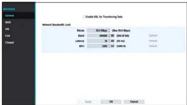
- Enable SSL for Transferring Data: Applies SSL (Secure Sockets Layer) protection on remote viewing and recording data transmissions.

- If using the SSL feature, it will not be possible to connect to the NVR from a remote program or a network keyboard that does not support SSL.
- Changing the SSL setting temporarily severs all remote connections to the NVR in order to apply the change.
- This product contains content developed by OpenSSL Project for use in Open SSL Toolkit (http://www.openssl.org/).
- Network Bandwidth Limit: Configure the network bandwidth sent to the remote locale.
- Bitrate: Set the size of the bandwidth.
- Burst: Set the burst-byte or buffer byte size.
– Latency: Set the latency. - MTU: Set the maximum transmission unit (MTU).

If you configured Network Bandwidth Limit, the live video may not display smoothly in a remote program.
WAN
Designate the IP address type as IPv4_None, IPv4_Manual, IPv4_DHCP, IPv6_None or IPv6_Link-local.
IPv4_None
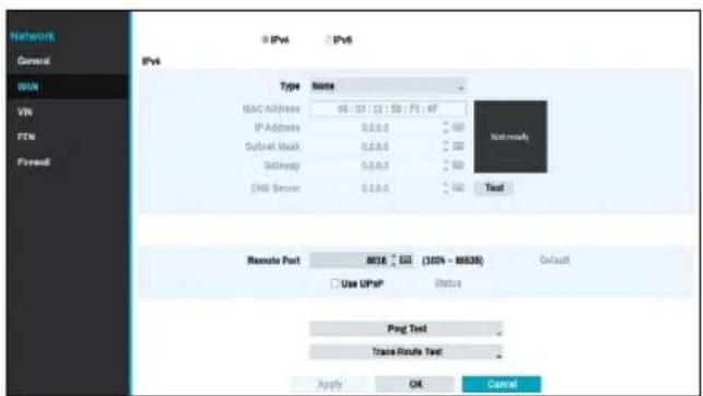
Select None and then save to disable IPv4 mode.
IPv4_Manual
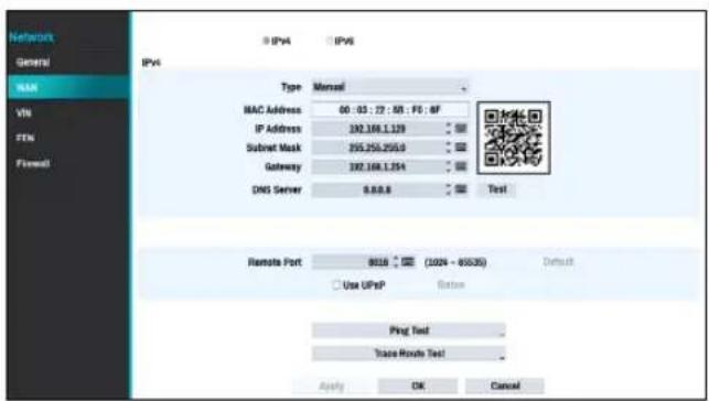
- Set Type to Manual.

Manual lets you configure related settings manually. Configure IP Address, Gateway, and Subnet Mask settings manually using virtual keyboard's arrow buttons.
- DNS Server: Enter the DNS server's IP address. The IP address can also be entered using the virtual keyboard.
- Remote Port: The port used by the remote program to connect to the NVR. Choose a value between 1024 and 65535. The port number can also be entered using the virtual keyboard.
- Ping Test: Select to test the current WAN settings you made.
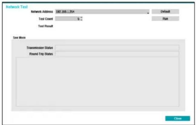
1 Enter the IP address of the NVR.
2 Adjust the frequency of the ping test.
3 Select Run to do the test. The test result is displayed.
4 Select Close to exit.

- If using a firewall, select Change Port to change the port number to one that is permitted by the firewall.
- Changing the port temporarily severs the NVR's remote connection.

Remote point IP and port settings on the remote program must also be changed in order for it to connect to the NVR.
- To use the UPnP (Universal Plug and Play) feature, select Use UPnP. If using an IP router (or NAT), UPnP service allows the device to automatically forward the port to the NVR.

- This port is used to access a port that has a private IP address.
- In order to use the UPnP service, the IP router (or NAT) must support UPnP port forwarding and have the relevant options enabled.
- Port number cannot be changed with Use UPnP selected.
- Status: Indicates the number of the port forwarded by the IP router (or NAT) to the NVR via UPnP service.
- Trace Route Test: The NVR tries to trace a network path to its destination.
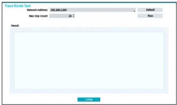
1 Set the network address of the destination.
2 Set the maximum number of hops.
3 Select Run to do the test. The test result is displayed.
4 Select Close to exit.
Part 2 - Configuration
IPv4\_DHCP
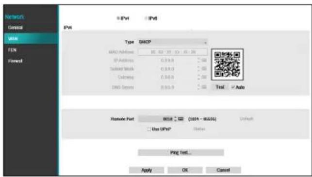
Select DHCP and then Save to retrieve IP address and other network settings automatically from the DHCP server. Once the network settings have been retrieved, the NVR's current IP address is displayed in the IP Address field.

- It may not be possible to retrieve the IP address if there is no DHCP server. If this is the case, contact your network administrator.
- With DHCP, the NVR's IP address might change with each startup.

There is a limit to the number of users allowed to connect remotely at the same time. Contact the service center for more information.

When registering nvr with the Idis mobile application, you can easily enter the IP address by using the QR code
IPv6\_None
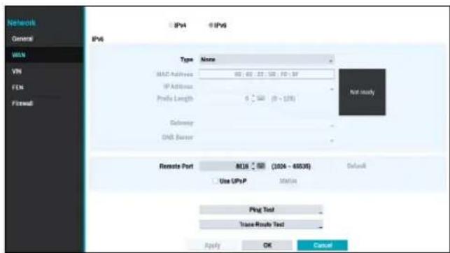
Select None and then save to disable IPv6 mode.
IPv6\_Manual
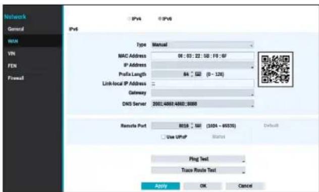

- Manual lets you configure related settings manually. Configure IP Address, Prefix Length, Gateway, and DNS Server settings manually using the remote control's arrow buttons or the virtual keyboard.
- When registering NVR with the IDIS mobile application, you can easily enter the IP address using the QR code.
IPv6\_Link-local
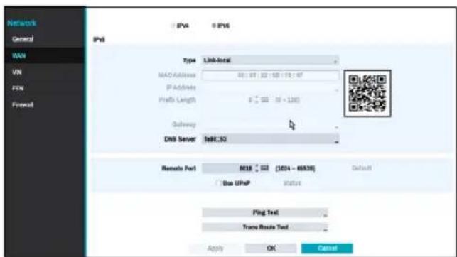
Configure the Link-local address. It is used by nodes when communicating with neighboring nodes on the same link.
VIN
If the camera is networked but not scanned, use this setup. This setup allows you to change the network setting of the NVR's VIDEO IN port which is camera's network environment. Check the camera's network setting first before you use this setup.

- Check the camera's network setting first before you use this setup.
• Make sure that this setting does not conflict with the WAN setting.
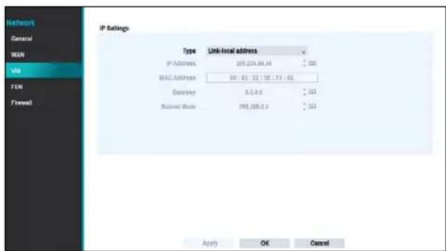
- Link-local address: Indicates the default IP address of VIDEO IN port.
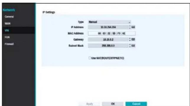
- Manual: Allows you to enter the IP address and other network settings manually.
- Use NAT(ROUTER/VPN/ETC): Allows access to other subnets. (It is not recommended to use this function unless you are a network expert.)
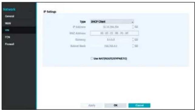
- DHCP Client: Retrieves an IP address and other network settings automatically from a DHCP server.
- Use NAT(ROUTER/VPN/ETC): Allows access to other subnets. (It is not recommended to use this function unless you are a network expert.)
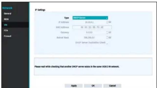
- DHCP Server: It makes the NVR run as a DHCP server. Check if there is another DHCP server on the same network. If there is no DHCP server, this option is enabled. The NVR allocates an IP address automatically in the range of 10.10.0.128 to 10.10.254.254 by using DHCP to the camera connected to the NVR's VIDEO IN port.

When several NVRs exist in the same network, only one of NVRs has to be run as a DHCP server. If several DHCP servers are running, the redundant IP may be allocated to the camera.
FEN
If using a dynamic IP address, FEN service makes it easy to connect to the NVR from a remote program without having to configure dynamic IP or router settings.
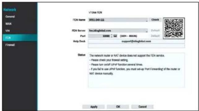
- Use FEN: Check if you wish to use FEN service.
- FEN Name: After entering the NVR name you wish to register on the FEN server, check and register the entered name. This is a unique NVR name that will be registered on the FEN server.

- You will not be able to save FEN settings unless you click on the Check button next to the NVR Name field and check the entered name's availability.
- You will be prompted with an error message if you do not enter NVR name or enter a name already registered to the FEN Server.
- If you leave the FEN name blank, it automatically changes to the default name.
- FEN Server: Enter the FEN server's IP address or domain name.

If you have configured the DNS Server setting under Network - WAN, you can enter the FEN server's domain name instead of its IP address in the FEN Server field.
- Port: Specify the FEN server's port number.

If using an IP router (or NAT), port configuration and other network functions will depend on the usage method of the IP router (or NAT).
- Status: Used to check the status of the device being registered to the FEN server.
Select Save after making changes to register the NVR's name to the FEN server.

If FEN has been configured correctly, the FEN server's help desk information will be displayed in the Help Desk field the next time you access the FEN Setup screen.

When registering nvr with the Idis mobile application, you can easily enter the IP address by using the QR code.
Firewall
Setting up a customized firewall rule set, it allows or denies access such as specific MAC address, IP address and receiving network port of the NVR.
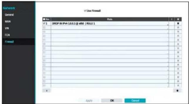
Select Use Firewall to activate firewall function. Click the + icon at the bottom of the list to set up a firewall rule.
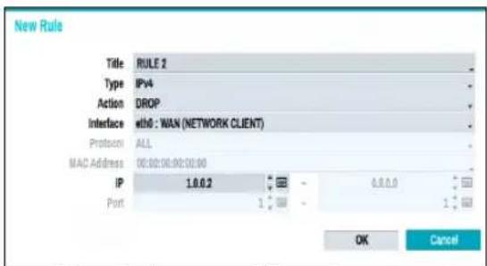
• Title: Edit the name of the rule.
- Type: Set the IP address, the MAC address or the network port.
- Action: Select which actions to apply this firewall rule to.
- Drop: Discard the packet that matches all the specified conditions.
- Reject: Deny the packet that matches all the specified conditions and send back an ACK packet telling it that the "packet was dropped" to the sender.
- Accept: Allow the packet that matches all the specified conditions.
- Interface: Specify the ethernet interface. It refers to a WAN (Network Client) or VIN (Video-In).
- Mac Address: If the rule is set to MAC address, enter the sending MAC address
- IP: If the type of the rule is set to IPv4 or within the IPv4 scope, enter the sending IP address.
- Port: If the type of the rule is set to port or within the port scope, enter the receiving network port number of NVR.
Notification Setup
Schedule
Select the + icon at the lower left corner of the screen to add a notification schedule.
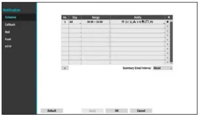
- Day: Add different schedules for different days of the week.
- Range: Change the event notification time frame.
- Notify: Select which notifications to generate when an event occurs. Select Mail, LAN 1 through 5, Push, HTTP, and/or Summary.

- In order to use the Notification (Callback) feature, the NVR must be registered on the remote program.
- Select the ✗ icon to delete the existing schedule.
- Summary Email Interval: Transmit event summary emails to a remote destination at specified intervals.
Callback
Configure Callback settings.
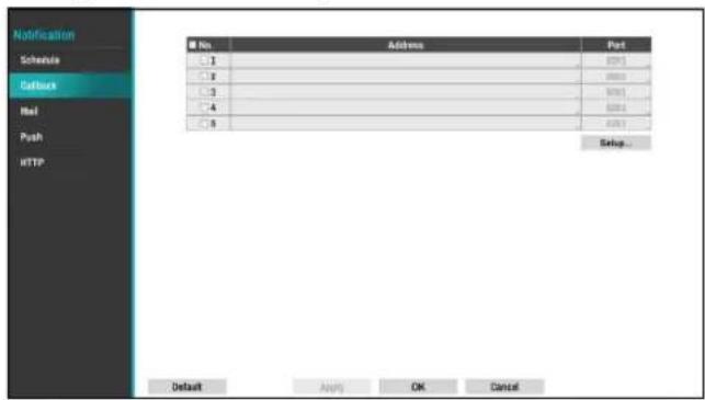
Enter the IP address of the receiving server and set Retry to between 1 and 10 in case of connection failure. Select the Setup... button at the lower right corner of the screen to configure Callback Retry Policy.
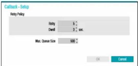
- Retry Policy: Configure a policy to retry a callback event.
- Retry: Number of times to retry a callback event. - Dwell: Wait time (in seconds) between retry attempts
- Max. Queue Size : Determine the maximum number that can be processing events. You can limit from 300 to 1000 queues. For more information on Callback Retry Policy, refer to the graph below.
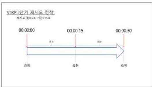
Configure Mail settings.
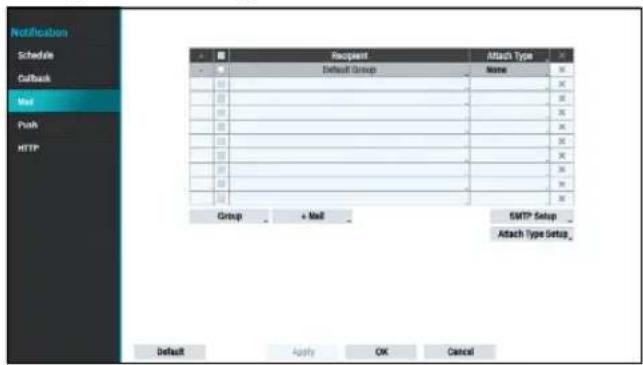
- +Group: Add a recipient group and select the image file format attached to an email.
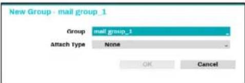
A virtual keyboard appears allowing you to enter the Group name. When selecting MP4, the NVR will attach the event detected image file (MP4 format) to an email.
• +Mail: Add a mail recipient
Select the group name and then assign the Group to Recipient. Enter the the recipient's e-mail address and mail server provider. Select the ★ icon to select the mail server provider from a list of registered SMTP mail server providers.
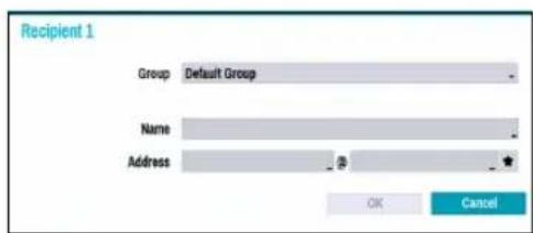

The recipient's mail address must be in the correct email format and contain the @ symbol.
Select the Attach Type to attach event recordings to outgoing mails to an account that belongs to that group.
Select the ☒ icon to remove the account and added group.
SMTP Setup
Select SMTP Setup at the bottom right corner of the screen to configure an SMTP server.
1 Select the SMTP server Type.
2 Enter the SMTP Server's IP address or domain name and then configure the Port and Sender settings.
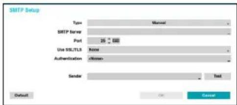
Default SMTP server port number is 25. Select Test to send out a test mail using the current settings.
Select SS/TLS or STARTTLS, depending a method of supporting a secure connection.

- If you have configured the DNS Server setting under Network - WAN, you can enter the STMP server's domain name instead of its IP address in the SMTP Server field.
- Address entered under Sender must be in the correct email format and include the @ symbol.
If user authentication is required by the SMTP server, select Use and then enter the User and Password information.
3 Select OK to apply and exit.

This product contains content developed by OpenSSL Project for use in Open SSL Toolkit (http://www.openssl.org/).
Attach Type Setup
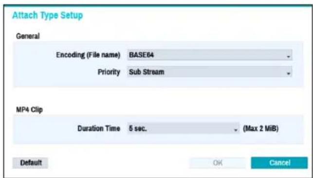
- Encoding (File name): Set the encoding for the name of the attached files to BASE64 or PLAIN-TEXT.
- Priority: Set the stream video for email and FTP attached files to Main Stream or Sub Stream.
- MP4 Clip: When sending an e-mail, event recordings will be attached and you can set the time to record MP4 clips.

Event recordings are attached only for the event that the camera generates.
Push
Configure Push settings.
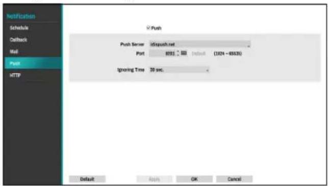
Select Push to use Push feature.
The Push feature sends out event-related messages to mobile phone.

Enable to receive the event occurred in NVR on the mobile phone(Android, iOS). The NVR must be registered and set in mobile phone.
HTTP
Notify or forward the events on remote HTTP servers. The event and NVR information are sent to HTTP servers in a JSON format.
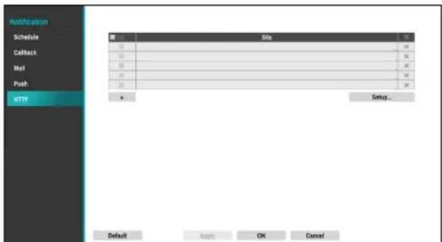
Click the + icon at the bottom of the list to enter the HTTP server information.
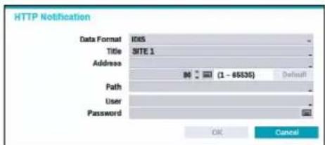
- Data Format: Set the data format of transmitted messages.
• Title: Enter the name of the HTTP site.
- Address: Enter the address of HTTP notifications.
- Path: Enter the path of HTTP server address.
- User / Password: Enter the user and password to access the HTTP site.
HTTP Notification Setup
An attribute and parameters must be included when sending the http requests. Click the Setup... icon at a bottom right corner of the window. When the following window appears, click the + button to set the HTTP attributes such as the type, name and value.
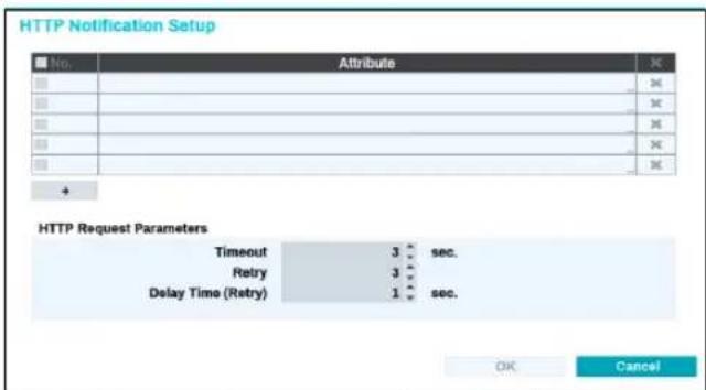
- HTTP Request Parameters: Set a specific response to an HTTP request.
- Timeout: Set the maximum time allowed for connection.
- Retry: Set the number of times to reconnect when a connection fails.
- Delay Time (Retry): Configure the time interval between each retry attempt (initial delay between retry attempts)
HTTP Notification Attribute
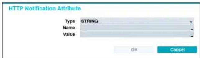
- Type: Select the corresponding type such as BOOL, INT32, FLOAT32 and STRING.
- Name: Enter the name of HTTP notification attribute.
- Value: Enter the value of HTTP notification attribute.
Display Setup
Refer to the Menu Use on page 29 for basic information on using the Setup menus.
OSD
Show OSD (On Screen Display) information on the bottom of the screen.
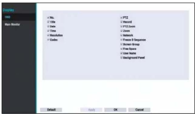
Status
- Date and Time: Displays the date and time.
- Network: Displays the icon when the unit is connected to a network via Ethernet.
- Free Space: Displays whether or not the NVR is in the recycle mode, and displays the available storage space when not in the recycle mode.
- User Name: Displays the current user logged in.
- Background Panel: Displays background panel at the bottom of the screen in black.
Camera
- No.: Displays the camera number on the upper left corner of the camera screen.
- Title: Displays the camera name on the upper left corner of the camera screen.
- Record: Displays recording and schedule icons.
• PTZ: Displays the icon on PTZ cameras.
- PTZ Zoom: Displays the zoom magnification (e.g. x2, x3, etc.)
- Resolution: Displays the recording resolution.
• Codec: Displays the codec information.
• Zoom: Displays a zoomed in state.
Part 2 - Configuration
- Freeze & Sequence: Displays freeze and sequence icons.
• Screen Group: Displays the current screen's group.
Main Monitor
Configure monitor-related settings.
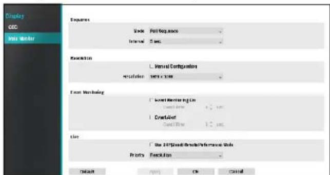
- Mode: Select Full Sequence or Cameo Sequence.
- Interval: Select between 3 secs and 2 mins. For more information on Sequence, refer to the 7 Sequence on page 23.
- Manual Configuration: Set the resolution manually regardless of the resolution supported by the monitor.
- Resolution: Select from 1920 x 1200, 1920 x 1080, 1680 x 1050 and 1600 x 1200.
- Event Monitoring On: With Event Monitoring enabled, the camera screen linking event monitoring is shown. For more information on Event Monitoring, refer to the Event Monitoring on page 26.
- Event Alert: With Event Alert selected, the red line appears on the top of the camera screen linking event monitoring when an event occurs.

• Supported resolutions may be restricted depending on the monitor.
• We recommend using 1920 x 1080 resolution.
- If you use a VGA monitor as the main display, we recommend that you use a resolution of 1920 x 1080 or below.
• HDMI deep color feature is not supported.
- Use BRP(Boost Remote Performance) mode: With BRP mode on, the camera full screen does not display in live mode and the network bandwidth can limit to 50Mbps.
- Priority : Select the camera's live stream priority, either resolution or frame rate.
Status Setup
Refer to the Menu Use on page 29 for basic information on using the Setup menus.
Camera
This screen displays an overview of camera events. When an event occurs, the corresponding channel flashes for 5 seconds.
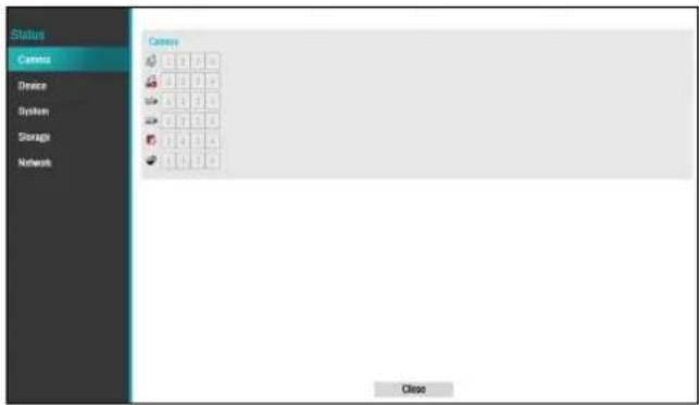
Event Types
| Motion Trip Zone | |||
| Tampering Video Loss | |||
| PIR Auto Tracking |
Device
This screen displays an overview of device events. When an event occurs, the corresponding channel flashes for 5 seconds.
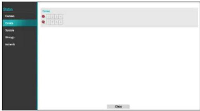
Event Types
| [DOYS] | **Recording Fail of Main Stream | **Recording Fail of Sub Stream |
** The two events are supported by some products only.
System
This screen displays an overview of system events. When an event occurs, the corresponding channel flashes for 5 seconds.
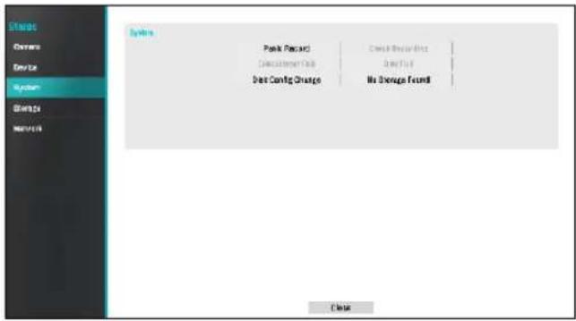
- Panic Record: Displays event status based on current Panic Record status.
- Check Recording: Displays event status based on System Monitoring settings. For more information, refer to the Self-Diagnosis on page 38.
- Disk Almost Full/Disk Full: If the storage device is not in Recycle status, event status is displayed when the amount of disk space specified under System Monitoring is reached and when the disk becomes 100% full. For more information, refer to the Self-Diagnosis on page 38.
- Disk Config Change: It will be highlighted when the NVR reboots after the hard disk drive has been replaced.
- No Storage Found: It will be highlighted when no recordable storage device has been found.
Storage
Indicates each disk's status.
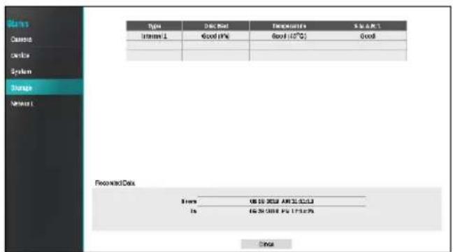
Configure Disk Bad and Disk Temperature settings under Setup > System > Monitoring.
| Disk Bad | Not Formatted | A disk that has never been used before. |
| Good | Disk performing normally.If the HDD is partially damaged, indicates the bad sector percentage. | |
| Error | If the HDD's bad sector ratio is higher than as designated by the user.Generates a system event. | |
| Temperature | N/A | Unable to detect the disk's temperature. |
| Good | Operating within normal temperature range. | |
| Bad | Disk temperature higher than as designated by the user.Generates a system event. | |
| S.M.A.R.T. | N/A | A disk that does not support S.M.A.R.T. |
| Good | A disk with normal S.M.A.R.T. status. | |
| Bad | A disk with abnormal S.M.A.R.T. status.Possibility of damage within 24 hours. |

- Check each disk's data storage time information under Recording Data.
- Clicking the temperature, S.M.A.R.T can check the each HDD information.
Network
This page provides a complete overview of the network status in real-time.
When you click the ? button, you can find the maximum PoE power value of each adapter available on the NVR system.
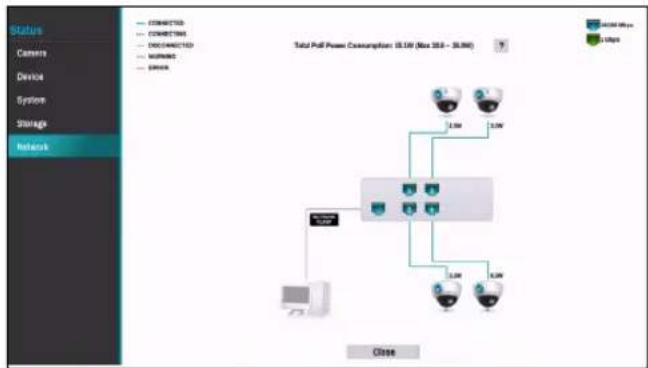
flowchart
graph TD
    A["Central Network"] --> B["1.0V"]
    A --> C["2.0V"]
    A --> D["3.0V"]
    A --> E["4.0V"]
    B --> F["Server"]
    C --> F
    D --> F
    E --> F
    F --> G["Close"]
    style A fill:#f9f,stroke:#333
    style B fill:#ccf,stroke:#333
    style C fill:#ccf,stroke:#333
    style D fill:#ccf,stroke:#333
    style E fill:#ccf,stroke:#333
    style F fill:#cfc,stroke:#333
Information shown include camera connection status, LAN port link status, power consumption, number of connected clients, and network connection info.
| Camera Connection |  indicates the camera is connected. 📋 indicates the camera is not connected. Clicking the image displays the camera's channel number. Clicking the image displays status information of the device connected to the NVR. indicates the camera is connected. 📋 indicates the camera is not connected. Clicking the image displays the camera's channel number. Clicking the image displays status information of the device connected to the NVR. |
| Network Switch | indicates a network switch is connected to the LAN port and shows how many cameras are connected. Clicking the image displays the camera's channel number. Clicking the image displays status information of the device connected to the NVR. |
| Video Encoder | indicates a video encoder is connected to the LAN port and shows how many cameras are connected. Clicking the image displays the camera's channel number. Clicking the image displays status information of the device connected to the NVR. |
| LAN Port Link | indicates a camera or a network switch is connected.indicates neither is connected. |
| Power Consumption | If receiving power from the NVR, the actual amount of power consumed by each camera is indicated under each camera icon. Total power consumption is shown at the top of the screen.[PoE Power Consumption: 15.1W (Max 35.0W)]Total PoE Power Consumption: 15.1W (Max 30.0 - 35.0W)Ports 1 through 4 in PoE-enabled products support PoE.NETWORKCLIENT(NETWORK CLIENT) ports do not support PoE. |
Part 2 - Configuration
| Number of Connected Clients | Indicates whether there are clients connected to the NVR via an external network and how many clients are connected.indicates at least one client is connected. indicates no client is connected. |
| Network Connection Info | Indicates network connection statuses (connected, connecting, disconnected, and connection error) using following lines:CONNECTEDCONNECTINGDISCONNECTEDWARNINGERROR(WARNING: When PoE switch is connected and network bandwidth is less than 100Mbps)(ERROR: When PoE switch is connected and network bandwidth is less than 10Mbps) |
Time-Lapse Search
While in Live mode, select the Search Mode icon and select Time-Lapse Search, or Event Log Search.
Search Menu

① Layout
Used to change the screen layout to single screen, 1x2, corridor format or 2x2.
② Previous/Next Group
Loads the previous/next screen group.
③ Display
- Full Screen On: Display the screen with a 16:9 aspect ratio. When you place the mouse at the bottom of the screen, the interface screen related to playback will appear. Refer to detailed explanations on the next page.
- Full Screen OFF: Display Time-Lapse Search screen.
- Camera OSD On/Off: Enables/disables the camera OSD feature.
- Status OSD On/Off: Enables/disables the status OSD feature.
- Aspect Ratio On/Off: Setting On displays video on the camera screen in its original ratio.
④ Database
- Record: Search recording data contained in the main recording device.
- Other: Search data recorded while disks used in other systems were connected.
⑤ Panic Record
Use the Panic Record feature.
⑥ Camera
Select a camera channel and display it as a single screen.
⑦ Live Mode
Activates Live mode.
⑧ Search Mode
Search by changing Time-Lapse Search and Event Log Search.
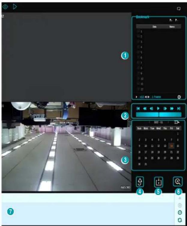
① Bookmark
Select the 📋 icon to add a bookmark to the current playback position.
Select a bookmark from the Bookmark setup window on the right side of the Time-Lapse Search mode screen to move to the registered playback position.
Select Bookmark list and then the ➕ icon to delete the corresponding bookmark.

The maximum number of bookmarks that can be saved is 12.
② Playback Controls
Play and scan through video recordings.
- Jog Shuttle
Adjust the playback method and speed.
Jog shuttle's vertical indicator indicates the current playback direction and speed. Vertical indicator placement to the right of the center means the video is being played back in the forward direction.
Placement to the left means the opposite. Farther away the vertical indicator from the center, faster the playback speed. Click and drag the vertical indicator
to adjust the playback speed. Releasing the mouse button returns the vertical indicator to the center and stops video playback.
- Slow Play
Search the playback screen at low speeds. Select the desired playback speed (x1/2, x1/3, x1/4, x1/6, x1/8) and then select Play.
③ Calendar Search
Use the calendar to search for video recordings by specific dates.
Dates containing video recordings are highlighted in light blue. Selecting a date containing video recording data loads the earliest recording from that date (paused state). Selected date is highlighted in orange.
④ Move
Search video recordings based on date and time. Specify the date and time and then select Go to jump to the corresponding video recording.
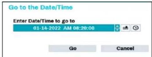
Select a (bookmark) button on the right side to move to the saved bookmark position.
⑤ Clip-Copy
- A-B Clip Copy: Designate a start point and an end point and copy the data in between.
- Clip Copy: Opens up the Clip Copy Setup window for designating points A and B.
⑥ Zoom
Zoom in.
⑦ Record Table
Display the current channel's recording information.

bar
| Time | Value | |---|---| | 08:29:00 | 0.246 | | 15:00:00 | 0.348 | | 22:00:00 | 0.348 | | 29:00:00 | 0.348 |Recording date and time are shown on the top of the search window. The gray indicator line on Record Table indicates the current playback position.-Alternatively, use the mouse to jump to the desired playback position.

• Farther back the data is on the record table, the more recent it is.
- If the system's clock is changed to a previous date and time, it is possible for multiple recordings with the identical time stamp to exist. Overlapped segments are highlighted in yellow.
Select (zoom-in) to compose recording data in 1-minute segments and select (zoom-out) to compose recording data in 3-minute segments. Selecting zoom-out displays more time in one screen than zoom-in screen.
If recording from points in time prior or after the time frame displayed on the screen is available, scrolls appear on both ends of the date and time information line. With a mouse, click and drag the vertical scroll bar to check recording data.
Display the latest update recording information when selecting 🔒 (Refresh).

Recording Data Bar Colors
| Blue Time Lapse Recording | |
| Purple Event Recording | |
| Yellow Pre-Event Recording | |
| Red Panic Recording | |
| Green | -Faulty recording due to a temporary disruption in device connection |
Context Menu
Right-click on the Camera screen to access the context menu.
- Zoom: Zoom in.
- Edit Group: Rearrange the split screen layout.
Clip Copy
Clip Copy
Select Clip-Copy – Clip Copy from the Search menu while in Live or Playback mode to open up the Clip Copy setup window. Specify the From and To settings.
A-B Clip Copy
Designate a start point and an end point and copy the data in between. Select Clip-Copy – A-B Clip Copy from the Search menu to set point A. The ▶ icon will appear on the status indicator area on the upper right corner of the screen. Select Clip-Copy – A-B Clip Copy once again to set point B. The Clip Copy Setup window will appear. Select A and B points are automatically applied as From and To values.
![Clip-Copy Data Source Record From First 01-14-2022 AM 08:20:00 To Last 01-14-2022 AM 08:20:00 Channels 1~4 Password Dest. 1. SanDisk Ultra [15.37 GB] File name 20220114.exe Include ClipPlayer Sub Stream First Use Site Info Progress Export ClipPlayer Start Close](/content/2026/05/1015987/images/ddd767e244938242643b51c4eb919b3930f6607ae82e3cb4b71490545b506e34.jpg)
- Channels: Specify which channel to save the recording to.
- Password: Enable password protection for the saved video clip and assign a password.
- Dest.: Select which storage media to use.
- File name: Designate a name for the file. The name may be up to 63 characters in length.

Special characters such as \, /, :, ;, *, ?, !, ", <, >, and | are not permitted.
- Include ClipPlayer: Enabling this option will save the video clip as an .exe file with clipplayer.
- Sub Stream First: If the video clip has dual recording information, the sub stream is saved first.
- Use Site Info: Adds Site info to the Clip Copy file's name.

Special characters contained in the location info (such as \, /, :, :, *, ?, !, ", <, >, and |) will be replaced with _ when the information is added to the file name.
- Export Clipplayer: Enabling this option will save the copied clip(.cbf) as a clipplayer to be played.
Selecting Start displays a calculation on the size of the data to be copied. Check the calculation and then select Continue to proceed. While Clip Copy is in progress, you can select Cancel to cancel the process or select Close to allow the window to run in the background. Selecting Close does not cancel Clip Copy. Once the process is complete, you will be prompted with a confirmation window.
Click Export ClipPlayer button to save the clipplayer.exe file playing CBF files to USB.

- The NVR displays the volume as 30GB regardless of the actual disk volume and the maximum size limit on Clip Copy files is 30GB. Clip Copying a segment that is more than 2GB in size produces multiple files that are up to 2GB in size, each.
- Clip Copy files can be played back on Windows systems. For more information, refer to the IDIS Center operation manual.
- For USB flash memory devices, the NVR supports the FAT32 file format only.

Do not disconnect the USB cable or power off the USB device while USB Clip Copy is in progress. Doing so can cause the NVR to malfunction or critically damage the external USB device's file system. You may be prompted with an error message when trying to back up on the device. If so, you will need to restart the NVR. If the USB hard disk's file system has been damaged, restarting the NVR will not solve the problem and the aforementioned error message will continue to be displayed each time you attempt a backup. If this is the case, you will need to format the HDD or use a recovery program to repair the damage to the drive's file system.
Event Log Search
Select Search Mode > Event Log Search to bring up the Event Log Search window.
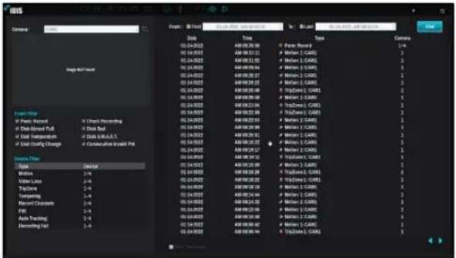
Select an eent to display the recording made on the selected time and date (paused state). Select the Play button in the middle of the screen to start playing back the recording. Use the drop-down menu above to load recordings from other cameras.
- Selecting the specific event displays the screen to be stationary. By clicking the 📋 button on the camera right, you can copy the event.
- You can uncheck the First and Last options at the top of the Event Log Search window and specify the search time frame manually.

Select First for From and Last for To to select the entire recording from start to end.
- If designating From or To settings manually, you will be able to enable/disable the Check Time Overlap option.
- Exceed the People Limit: Select which channels to search Exceed the People Limit events in.
- Exceed the Time Limit: Select which channels to search Exceed the Time Limit events in.

If the system's clock has been changed and the designated From or To point exists at more than one location, you will have to choose one. Only the events that took place between the selected From and To points will be searched. If Check Time Overlap has not been selected, events from the entire From and To range will be searched.
- Use event filters to include/exclude specific system events such as Panic Record, Check Recording, Disk Almost Full, Disk Bad, Disk Temperature, Disk S.M.A.R.T., and Disk Config Change from the search.
Device Filter
- Motion: Select which channels to search motion detection events in.
- Video Loss: Select which channels to search video loss events in.
- Trip Zone: Select which channels to search trip zone events in.
- Tampering: Select which channels to search tampering events in.
- Record Channel: Select which record channels to search events in.
- Recording Fail: Select which channels to search recording fail events in.
- PIR: Select which channels to search PIR events in.
- Auto Tracking: Select which channels to search Auto Tracking events in.

Selected record channels are searched for events with at least one linked recording. If no camera is selected, only the events with no linked recording camera are searched.
Overlapped Recording Search
If the system's clock is changed to a point in the past, overlapping recordings may be produced. Overlapped recordings have to be searched in segments.
For example, making a recording from 1 o'clock to 5 o'clock, changing the system's clock at 5 o'clock to 3 o'clock, and then continuing to record until 6 o'clock produces two recordings that overlap between 3 o'clock and 5 o'clock. This results in two segments for the period between 3 and 5.
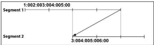
When searching overlapped video recordings, you can choose a specific point in time or a time frame. If you use the Go to the Date/Time option and select a point within the overlapped time period (4 o'clock, for example), you must specify 4 o'clock in which of the two existing segments.
Select a Segment
1: Segment 20
2: Segment 21
If you use the Event Log Search or Motion Detection option and select a time frame within the overlapped time period (4 o'clock to 5 o'clock, for example), you must choose between the two redundant sets of From and To values. Selectable search ranges are as follows:
• 4 o'clock in segment 1 to 5 o'clock in segment 1
• 4 o'clock in segment 1 to 5 o'clock in segment 2
• 4 o'clock in segment 2 to 5 o'clock in segment 2
Select a Range
1: Scope 1 \~ 3
2: Scope 1 \~ 2
3: Scope 2 \~ 2
Memo
IDIS®
IDIS Co., Ltd.
For more information, please visit at
www.idisglobal.com
- Network Video Recorder
- Safety Precautions
- CAUTION
- WARNING
- AVERTISSEMENT
- Read Instructions
- Retain Instructions
- Cleaning
- Attachments
- Water and/or Moisture
- Ventilation
- Accessories
- Power Sources
- Power Cords
- Lightning
- Overloading
- Objects and Liquids
- Servicing
- Damage requiring Service
- Replacement Parts
- Safety Check
- Field Installation
- Correct Batteries
- Elevated Operating Ambient Temperature
- Reduced Air Flow
- Mechanical Loading
- Circuit Overloading
- Reliable Earthing (Grounding)
- HDMI Port Precautions
- In-Text
- Symbol Type Description
- User's Caution Statement
- FCC Compliance Statement
- WEEE (Waste Electrical & Electronic Equipment)
- Correct Disposal of This Product
- Copyright
- Registered Trademarks
- 1
- Part 1 - Getting Started ....9
- 2
- Part 2 - Configuration....29
- Camera Setup 40
- Record Setup....52
- Network Setup 64
- Notification Setup....69
- Part 3 - Search....79
- Setting Password
- Setup Wizard
- Quick Wizard
- Select Quick Wizard.
- Specify the current date and time and then click Next.
- Choose the desired Recording Method and click Next.
- Choose the desired Recording Quality and click Next.
- Choose the desired codec and click Next.
- Quick Setup Wizard (Step 5/6)
- Click Finish to exit Quick Wizard.
- Quick Setup Wizard (Step 6/6)
- Network Wizard
- Select Network Wizard.
- Specify whether the system is connected to the Internet and click Next.
- Click Finish to exit Network Wizard.
- Camera Registration
- Camera Scan Button
- Rescan
- Third Party Scan
- Select Scan to commence scanning.
- Set Camera Password
- Go To Camera
- Search Scope
- Screen Auto. Assign
- Camera list
- Scan Refresh Interval
- Camera View Buttons
- Camera List Area
- Video Display Area
- ① Camera Title
- ② MAC Address
- ③ Screen Position/Registration Info
- ④ Bitrate Allocation
- Camera Menu
- Apply/Cancel Buttons
- Diagnosis Process
- Camera Registration Mode
- Login
- Find Password
- Enter a user, registered email and then select Get Verification Code.
- Enter Verification Code and select OK.
- Enter an UPR(User Password Reset) verification and then click on UPR Verification button.
- Select the UPR file and then click on Import button.
- To set a new password, click the question mark button in the lower left corner and follow the instructions.
- Live Mode
- Live Menu
- ① Login/Logout
- ② Layout
- ③ Previous/Next Group
- ④ Display
- ⑤ Freeze
- ⑥ Panic Recording
- ⑦ Sequence
- Full Sequence
- e.g.) Full Sequence in 2x2 split screen mode
- Cameo Sequence
- e.g.) Cameo Sequence in 2x2 split screen mode
- ⑧ Status
- ⑨ Select Camera
- ⑩ Search Mode
- ⑪ Setup
- ⑫ Wizard
- ⑬ Status Indication
- Zoom
- PTZ Control
- Setting Up a PTZ Preset
- Event Monitoring
- Covert Camera
- Context Menu Access
- Edit Group
- Video Recording
- Panic Recording
- Video Recording Playback
- All Channel Playback
- Menu Use
- Text Input via Virtual Keyboard
- Batch Assignment
- Mouse
- System Setup
- General
- Date/Time
- User
- Authority (AB)
- Part 2 - Configuration
- Security
- Use 2FA
- Network Security (Host Certificates)
- Storage
- Self-Diagnosis
- - Reports
- Custom Value
- About
- Camera Setup
- Registration
- Device Scan
- Advanced Setup
- ① Preset
- ② Scan
- ③ Pattern
- ④ Tour
- Image Sensor Options
- White Balance Options
- Exposure Options
- - DC IRIS
- - P-IRIS
- View Options
- Miscellaneous
- Stream I
- Stream II
- Maintenance
- Record Setup
- Schedule
- Simple Mode Options
- Advanced Mode Options
- Pre-Event
- Event Setup
- System\_Event
- Camera System
- Camera System\_Video Loss
- Camera System\_Recording Fail
- Camera System\_PIR
- - Ignore Condition
- Video-Analytics
- Video-Analytics\_Motion
- Video-Analytics\_Trip Zone
- - Setup
- Video-Analytics\_Tampering
- Video-Analytics\_Auto Tracking
- Network Setup
- WAN
- IPv4\_DHCP
- IPv6\_None
- IPv6\_Manual
- IPv6\_Link-local
- VIN
- FEN
- Firewall
- Notification Setup
- Callback
- SMTP Setup
- Attach Type Setup
- Push
- Configure Push settings.
- HTTP
- HTTP Notification Setup
- HTTP Notification Attribute
- Display Setup
- OSD
- Status
- Camera
- Main Monitor
- Status Setup
- Device
- System
- Network
- Time-Lapse Search
- Search Menu
- ① Layout
- ② Previous/Next Group
- ③ Display
- ④ Database
- ⑤ Panic Record
- ⑥ Camera
- ⑦ Live Mode
- ⑧ Search Mode
- ① Bookmark
- ② Playback Controls
- - Jog Shuttle
- - Slow Play
- ③ Calendar Search
- ④ Move
- ⑤ Clip-Copy
- ⑥ Zoom
- ⑦ Record Table
- Context Menu
- Clip Copy
- A-B Clip Copy
- Event Log Search
- Puts - Record
- Dots - Record Pull
- Dots - Trackers
- Dots - CNA-1.1
- Dots - CNA-2.1
- Device Filter
- Overlapped Recording Search
- Select a Segment
- Select a Range
- Memo
- IDIS®
Brand : IDIS
Model : DR-1504P
Category : Video recorder