TR-2508 - Video recorder IDIS - Free user manual and instructions
Find the device manual for free TR-2508 IDIS in PDF.


| Product Type | Network Video Recorder (NVR) |
| Model | TR-2508 |
| Brand | IDIS |
| Dimensions | 19-inch rackmount, 2U height (approx. 88 x 482 x 400 mm) |
| Weight | Approximately 5 kg |
| Power Supply | 100-240V AC, 50/60Hz, 2A |
| Power Consumption | ≤ 35W (without hard drives) |
| Operating Temperature | 0°C to 40°C (32°F to 104°F) |
| Storage Temperature | -20°C to 60°C (-4°F to 140°F) |
| Humidity | 0% to 85% non-condensing |
| Video Input | 8-channel IP camera support |
| Recording Resolution | Up to 4K (3840x2160) per channel |
| Storage | Up to 2 SATA hard drives (3.5-inch, maximum 10TB each) |
| Network Interface | Dual Gigabit Ethernet ports |
| Audio | 1-channel audio input and 1-channel audio output |
| Main Functions | Continuous recording, motion detection, scheduled recording, remote live view, playback backup |
| Maintenance and Cleaning | Clean the exterior with a soft dry cloth; avoid liquid cleaners. Ensure proper ventilation. |
| Safety | Operate in a well-ventilated area; use a surge protector; do not block vents. |
| Spare Parts and Repairability | Contact an IDIS authorized dealer for replacement parts and repairs. |
| General Information | Compatible with IDIS IP cameras; supports ONVIF Profile S for third-party cameras. |
Frequently Asked Questions - TR-2508 IDIS
User questions about TR-2508 IDIS
0 question about this device. Answer the ones you know or ask your own.
Ask a new question about this device
Download the instructions for your Video recorder in PDF format for free! Find your manual TR-2508 - IDIS and take your electronic device back in hand. On this page are published all the documents necessary for the use of your device. TR-2508 by IDIS.
USER MANUAL TR-2508 IDIS
Digital Video Recorder
Operation Manual
TR-2508
This operation manual contains basic instructions on installing and using Digital Video Recorder, an IDIS product. Users who are using this product for the first time, as well as users with experience using comparable products, must read this operation manual carefully before use and heed to the warnings and precautions contained herein while using the product. Safety warnings and precautions contained in this operation manual are intended to promote proper use of the product and thereby prevent accidents and property damage and must be followed at all times. Once you have read this operation manual, keep it at an easily accessible location for future reference.

- The manufacturer will not be held responsible for any product damage resulting from the use of unauthorized parts and accessories or from the user's failure to comply with the instructions contained in this operation manual.
- It is recommended that first-time users of Digital Video Recorder and individuals who are not familiar with its use seek technical assistance from their retailer regarding product installation and use.
- If you need to disassemble the product for functionality expansion or repair purposes, you must contact your retailer and seek professional assistance.
- Both retailers and users should be aware that this product has been certified as being electromagnetically compatible for commercial use. If you have sold or purchased this product unintentionally, please replace with a consumer version.
Safety Precautions

CAUTION
RISK OF ELECTRIC SHOCK
DO NOT OPEN

CAUTION: TO REDUCE THE RISK OF ELECTRIC SHOCK,
DO NOT REMOVE COVER (OR BACK).
NO USER-SERVICEABLE PARTS INSIDE.
REFER SERVICING TO QUALIFIED SERVICE PERSONNEL.

The lightning flash with arrowhead symbol, within an equilateral triangle, is intended to alert the user to the presence of uninsulated "dangerous voltage" within the product's enclosure that may be of sufficient magnitude to constitute a risk of electric shock.

The exclamation point within an equilateral triangle is intended to alert the user to the presence of important operating and maintenance (servicing) instructions in the literature accompanying the appliance.
Important Safeguards
1. Read Instructions
All the safety and operating instructions should be read before the appliance is operated.
2. Retain Instructions
The safety and operating instructions should be retained for future reference.
3. Cleaning
Unplug this equipment from the wall outlet before cleaning it. Do not use liquid aerosol cleaners. Use a damp soft cloth for cleaning.
4. Attachments
Never add any attachments and/or equipment without the approval of the manufacturer as such additions may result in the risk of fire, electric shock or other personal injury.
5. Water and/or Moisture
Do not use this equipment near water or in contact with water.
6. Ventilation
Place this equipment only in an upright position. This equipment has an open-frame Switching Mode Power Supply (SMPS), which can cause a fire or electric shock if anything is inserted through the ventilation holes on the side of the equipment.
7. Accessories
Do not place this equipment on an unstable cart, stand or table. The equipment may fall, causing serious injury to a child or adult, and serious damage to the equipment. Wall or shelf mounting should follow the manufacturer's instructions, and should use a mounting kit approved by the manufacturer.

This equipment and cart combination should be moved with care. Quick stops, excessive force, and uneven surfaces may cause the equipment and cart combination to overturn.
8. Power Sources
This equipment should be operated only from the type of power source indicated on the marking label. If you are not sure of the type of power, please consult your equipment dealer or local power company.
You may want to install a UPS (Uninterruptible Power Supply) system for safe operation in order to prevent damage caused by an unexpected power stoppage. Any questions concerning UPS, consult your UPS retailer.
9. Power Cords
Operator or installer must remove power and TNT connections before handling the equipment.
10. Lightning
For added protection for this equipment during a lightning storm, or when it is left unattended and unused for long periods of time, unplug it from the wall outlet and disconnect the antenna or cable system. This will prevent damage to the equipment due to lightning and power-line surges.
11. Overloading
Do not overload wall outlets and extension cords as this can result in the risk of fire or electric shock.
12. Objects and Liquids
Never push objects of any kind through openings of this equipment as they may touch dangerous voltage points or short out parts that could result in a fire or electric shock. Never spill liquid of any kind on the equipment.
13. Servicing
Do not attempt to service this equipment yourself. Refer all servicing to qualified service personnel.
14. Damage requiring Service
Unplug this equipment from the wall outlet and refer servicing to qualified service personnel under the following conditions:
A. When the power-supply cord or the plug has been damaged.
B. If liquid is spilled, or objects have fallen into the equipment.
C. If the equipment has been exposed to rain or water.
D. If the equipment does not operate normally by following the operating instructions, adjust only those controls that are covered by the operating instructions as an improper adjustment of other controls may result in damage and will often require extensive work by a qualified technician to restore the equipment to its normal operation.
E. If the equipment has been dropped, or the cabinet damaged.
F. When the equipment exhibits a distinct change in performance ☒ this indicates a need for service.
15. Replacement Parts
When replacement parts are required, be sure the service technician has used replacement parts specified by the manufacturer or that have the same characteristics as the original part. Unauthorized substitutions may result in fire, electric shock or other hazards.
16. Safety Check
Upon completion of any service or repairs to this equipment, ask the service technician to perform safety checks to determine that the equipment is in proper operating condition.
17. Field Installation
This installation should be made by a qualified service person and should conform to all local codes.
18. Correct Batteries
Warning: Risk of explosion if battery is replaced by an incorrect type. Dispose of used batteries according to the instructions.
19. Tmra
A manufacturer's maximum recommended ambient temperature (Tmra) for the equipment must be specified so that the customer and installer may determine a suitable maximum operating environment for the equipment.
20. Elevated Operating Ambient Temperature
If installed in a closed or multi-unit rack assembly, the operating ambient temperature of the rack environment may be greater than room ambient. Therefore, consideration should be given to installing the equipment in an environment compatible with the manufacturer's maximum rated ambient temperature (Tmra).
21. Reduced Air Flow
Installation of the equipment in the rack should be such that the amount of airflow required for safe operation of the equipment is not compromised.
22. Mechanical Loading
Mounting of the equipment in the rack should be such that a hazardous condition is not caused by uneven mechanical loading.
23. Circuit Overloading
Consideration should be given to connection of the equipment to supply circuit and the effect that overloading of circuits might have on over current protection and supply wiring. Appropriate consideration of equipment nameplate ratings should be used when addressing this concern.
24. Reliable Earthing (Grounding)
Reliable grounding of rack mounted equipment should be maintained. Particular attention should be given to supply connections other than direct connections to the branch circuit (e.g., use of power strips).
In-Text
Symbol Type Description


Caution Important information concerning a specific function.
Note Useful information concerning a specific function.
User's Caution Statement
Caution: Any changes or modifications to the equipment not expressly approved by the party responsible for compliance could void your authority to operate the equipment.
FCC Compliance Statement
THIS EQUIPMENT HAS BEEN TESTED AND FOUND TO COMPLY WITH THE LIMITS FOR A CLASS A DIGITAL DEVICE, PURSUANT TO PART 15 OF THE FCC RULES. THESE LIMITS ARE DESIGNED TO PROVIDE REASONABLE PROTECTION AGAINST HARMFUL INTERFERENCE WHEN THE EQUIPMENT IS OPERATED IN A COMMERCIAL ENVIRONMENT. THIS EQUIPMENT GENERATES, USES, AND CAN RADIATE RADIO FREQUENCY ENERGY AND IF NOT INSTALLED AND USED IN ACCORDANCE WITH THE INSTRUCTION MANUAL, MAY CAUSE HARMFUL INTERFERENCE TO RADIO COMMUNICATIONS. OPERATION OF THIS EQUIPMENT IN A RESIDENTIAL AREA IS LIKELY TO CAUSE HARMFUL INTERFERENCE, IN WHICH CASE USERS WILL BE REQUIRED TO CORRECT THE INTERFERENCE AT THEIR OWN EXPENSE.
WARNING: CHANGES OR MODIFICATIONS NOT EXPRESSLY APPROVED BY THE PARTY RESPONSIBLE FOR COMPLIANCE COULD VOID THE USER'S AUTHORITY TO OPERATE THE EQUIPMENT.
THIS CLASS OF DIGITAL APPARATUS MEETS ALL REQUIREMENTS OF THE CANADIAN INTERFERENCE CAUSING EQUIPMENT REGULATIONS.
WEEE (Waste Electrical & Electronic Equipment)
Correct Disposal of This Product
(Applicable in the European Union and other European countries with separate collection systems)

This marking shown on the product or its literature, indicates that it should not be disposed with other household wastes at the end of its working life. To prevent possible harm to the environment or human health from uncontrolled waste disposal, please separate this from other types of wastes and recycle it responsibly to promote the sustainable reuse of material resources.
Household users should contact either the retailer where they purchased this product, or their local government office, for details of where and how they can take this item for environmentally safe recycling.
Business users should contact their supplier and check the terms and conditions of the purchase contract. This product should not be mixed with other commercial wastes for disposal.
Copyright
© 2021 IDIS Co., Ltd.
IDIS Co., Ltd. reserves all rights concerning this operation manual.
Use or duplication of this operation manual in part or whole without the prior consent of IDIS Co., Ltd. is strictly prohibited.
Contents of this operation manual are subject to change without prior notice.
Registered Trademarks
IDIS is a registered trademark of IDIS Co., Ltd.
Other company and product names are registered trademarks of their respective owners.
The information in this manual is believed to be accurate as of the date of publication even though explanations of some functions may not be included. We are not responsible for any problems resulting from the use thereof. The information contained herein is subject to change without notice. Revisions or new editions to this publication may be issued to incorporate such changes.
The software included in this product contains some Open Sources. You may obtain the corresponding source code which we have to distribute according to the license policy. Go to System Setup - About page for more information. This product includes software developed by the University of California, Berkeley and its contributors, and software developed by the OpenSSL Project for use in the OpenSSL Toolkit (http://www.openssl.org/). Also, this product includes cryptographic software written by Eric Young (eay@cryptsoft.com), and software written by Tim Hudson (tjh@cryptsoft.com).
1
Part 1 - Getting Started ....9
Login 9
Live Mode....10
Live Menu 10
Video Display Area 11
Edit Group....13
Zoom....13
PTZ Control 14
Event Monitoring ....16
Covert Camera 16
Status....16
Context Menu Access ....18
Video Recording....18
Panic Recording....18
Audio Recording ....19
Video Recording Playback ....19
All Channel Playback....19
Remote Control Buttons during Playback 19
Context Menu....19
2
Part 2 - Configuration....20
Menu Use....20
Text Input via Virtual Keyboard 20
Batch Assignment....21
Mouse....21
System Setup 21
General 21
Date/Time 27
User 28
System Event ....30
About....31
General 32
Schedule....33
Pre-Event 35
Event Setup 35
Motion....35
Alarm-In 37
Video Loss 37
Text-In....38
Camera Setup 39
General 39
PTZ....39
Privacy Masking....40
Device Setup....41
Audio....41
Alarm-Out 41
Network Setup 42
General 42
LAN....43
FEN....44
RTSP 45
IDIS Web 46
Notification Setup....46
Callback 46
Mail....47
Schedule....48
Display Setup 48
OSD 48
Main Monitor 49
Part 3 - Search....50
Searching Video....50
Search Menu....50
Context Menu....51
Event Log Search....52
Record Table Search....53
Text-In Search....54
Bookmarks....55
Clip Copy 55
Overlapped Recording Search ....57
4 5
Part 4 - IDIS Web....58
Web Live Mode....60
Web Search Mode....62
Part 5 - Appendix....65
Index 65
Login
Configuring the DVR's settings and accessing its searching and other functions require an authorized user login.
1 Bring up the Live menu and either press the SETUP button on the remote control or click on ⏻ (Login) using the mouse.
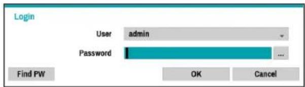
2 Select a user, enter the password, and then select OK.
3 Select Find PW from the login screen if you do not remember the password. Select a user and enter the E-mail address, and click Get Verification Code.
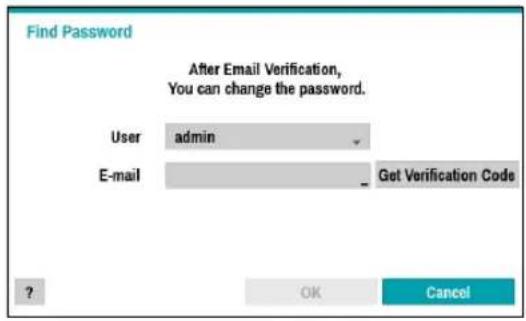
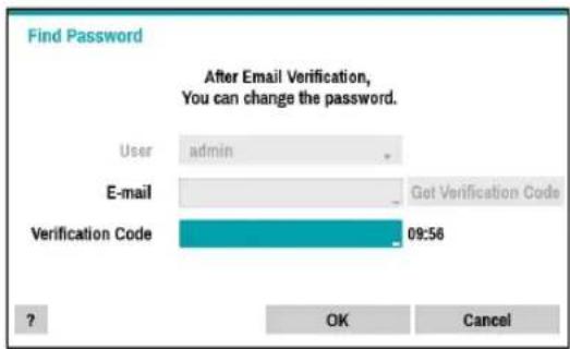
4 Enter the verification code you receive by e-mail and click OK.

- There is no default password for the admin account. Select admin and then OK without entering a password to log in.
•Leaving the admin account unassigned with a password poses a security risk. Please assign a password at your earliest convenience. A warning message will continue to be displayed until a password is assigned.
- Click on the ... button next to the password field using the mouse. This will bring up a virtual keyboard you can use to assign a password. For more information on using the virtual keyboard, refer to the Text Input via Virtual Keyboard on page 20.
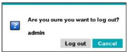
5 To log out, bring up the Live menu and click on Ⓤ (Log out) using the mouse.
Live Mode
Live Menu
Press the Setup button while in Live mode to bring up the Live menu on the right edge of the screen. Press Setup once more to hide the menu. Use the Arrow buttons on the front panel of the DVR or the remote control to select the menu options.
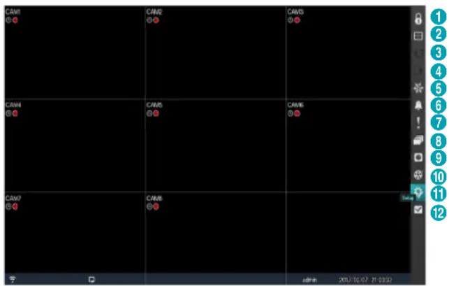
| 1 | Login/Logout |
| 2 | Display |
| 3 | Previous Group |
| 4 | Next Group |
| 5 | Freeze |
| 6 | Alarm |
| 7 | Panic Recording |
| 8 | Sequence |
| 9 | Camera Menu |
| 10 | Search |
| 11 | Setup |
| 12 | Status |

Placing the mouse pointer near the right edge of the screen also displays the Live menu.
- Login/Logout
Log into and out from accounts. If in the logged in state, the account ID is shown. If in the logged out state, the login icon is shown.
- Display
Used to change the screen layout to single screen, 2x2, 1x5, 1x7, 3x3.
– Camera OSD, Status OSD: Camera OSD or Status OSD On and Off.
- Previous/Next Group
Loads the previous/next screen group.
- Freeze
Freezes the screen. Select Freeze again to unfreeze.
- Alarm
Pressing this button while the alarm has been activated resets all DVR outputs, including the built-in buzzer.
- Panic Recording
Activates/deactivates Panic Recording.
- Sequence
Initiates Sequence in the same manner as pressing the SEQUENCE button while in Live mode. To exit, select Sequence once more or press the SEQUENCE button on the remote control. The 📋 icon is displayed at the bottom of the screen while Sequence is in progress.
Full Sequence
Displays all channels in sequence while in Live mode (single and PIP split screen settings).
e.g.) Full Sequence in single screen mode

Cameo Sequence
In Cameo Sequence mode, only the bottom right screen in a split screen-setup changes sequence. In order to use the Cameo Sequence feature, Cameo Sequence (Display Setup - Main Monitor > Sequence) must first be enabled.

- While in the Sequence mode, the sequence icon displays in bottom-left corner if Sequence is selected in the Display setup screen.
-
Pages are skipped under the following circumstances:
-
If all cameras included in the page are deactivated.
– If there are no video signals. - If the page contains "covert" cameras.
- If the user does not have permission to view feeds from the cameras.
- Camera Menu
- PTZ: Allows you to control the selected camera as long as it has Pan, Tilt and Zoom capabilities. It is the same as pressing the PTZ button.
- Zoom: Zooms the current image of the selected camera on the screen. It is the same as pressing the ZOOM button. Selecting Zoom again in the Camera Menu again exits the Zoom mode. Right-click on the mouse and drag to change the orientation, and use the wheel with the left-click on the mouse to zoom in/out more precisely.
– Audio: Enable/disable audio.
– Color Control: Allows you to control brightness, contrast, hue and saturation for each camera for the selected camera if a user who has Color Control authority logs into the system.
- Video Position: Adjusts the video position in left/right directions.
- Menu Control: Adjusts the camera's self-settings.

- Menu Control is supported only for the cameras that use Pelco-C/H-C Protocol and support UTC (Up The Coax) function.
-
Menu Control is not supported if the port is set to RS232 or RS485 in the PTZ setting.
-
Edit Group: Enter to the Edit Group mode in the split screen layout.
- Information: Displays currently connected camera information and recording status.
- Search
- All Channels: Exits the live monitoring mode and enters the search mode.
- Triplex: Enters the Triplex mode. Selecting the camera number plays back video of the selected camera.
- Setup
Used to access the Setup menu.
- Status
Allows you to check the status of the DVR's system, event and storage.
Video Display Area
Left-click on the video display area to toggle between split screen and single screen modes.
Drag the camera screens around to rearrange them.
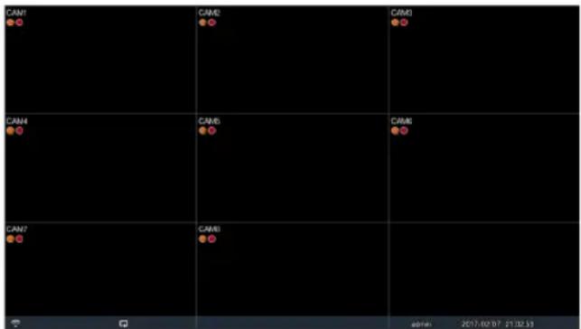
Camera Screen
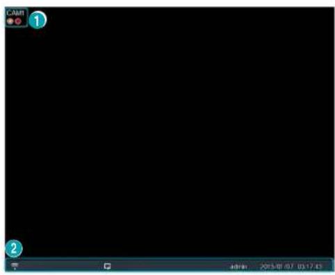
① Camera Title: Indicates the camera's title.
② Status Indication: Displays system status icons.
| Indicates remote control receptivity. | |
| Indicates connection to the DVR from a remote program. | |
| Indicates two-way audio connection. | |
| Indicates connection to the DVR using the VNC service. | |
| Indicates a zoomed in state. | |
| Indicates Freeze is in use. | |
| Indicates Sequence is in use. | |
| 1/2 Indicates the current screen's group. | |
| Indicates an event monitoring. | |
| Indicates HDD use. The icon to the left is shown if using the overwrite setting. Otherwise, remaining HDD space is shown as a percentage value. | |
Camera Menu
Right-click on the video display area to bring up the camera menu.
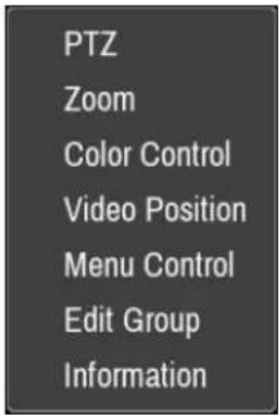
- PTZ: Allows you to control the selected camera as long as it has Pan, Tilt and Zoom capabilities. It is the same as pressing the PTZ button.
- Zoom: Zooms the current image of the selected camera on the screen. It is the same as pressing the ZOOM button. Selecting Zoom again in the Camera Menu again exits the Zoom mode.
• Color Control: Adjusts the camera's color settings. - Video Position: Adjusts the video position in left/right directions.
- Menu Control: Adjusts the camera's self-settings.

- Menu Control is supported only for the cameras that use Pelco-C/H-C Protocol and support UTC (Up The Coax) function.
-
Menu Control is not supported if the port is set to RS232 or RS485 in the PTZ setting.
-
Edit Group: Enter to the Edit Group mode in the split screen layout.
• Information: Displays currently connected camera information and recording status.
Edit Group
Edit Group lets you customize split screen pages in both Live and Search modes.
1 While displaying a split screen page, select the Edit Group option from the context menu. A yellow border is drawn around the page. Use the arrow buttons on the front panel or the mouse to select a different page.
2 Press a Camera button or select a camera after pressing the Menu button. Selected camera is then loaded on to the selected page. Repeat to assign other channels to the page.
3 Press the remote control's button to exit Edit Group. Alternatively, press the Menu button and then select Exit Group Edit to exit.

Edit Group will terminate automatically after 15 seconds of inactivity.
Zoom
Press the ZOOM button on the remote control and select a channel you wish to zoom in on. A zoom frame will appear on the selected channel. Use the arrow buttons to position the frame. Press the Play/Pause button to cycle through various zoom factors. When Zoom is activated, 🔒 icon is on the status bar located on the bottom of the system.

- In Full Screen mode, activating Zoom automatically selects the current channel.
- To restore the channel to normal size, press the Zoom button again.
- The available enlargement ratio is different from camera mode.
- FHD resolution is supported up to 7 times, and UHD resolution is supported up to 5 times.
PTZ Control
While in Live mode, right-click and select PTZ from the context menu or press the PTZ button on the DVR's front panel or remote control to display the PTZ camera selection window.
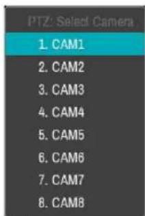
Select the camera you wish to control. The ocon will begin to flash on the selected camera's OSD window.
Use the Arrow buttons to pan and tilt the camera up, down, left, and right.
Use the · and · buttons to zoom in/out.
Use the 🔍 and buttons to shift focus from nearby to far and vice versa. You can also change the direction by dragging on the mouse.
Also, it's possible to use the mouse wheel to zoom in/out.

- Logging in with an account that has PTZ Control Authority is necessary in order to control PTZ cameras.
- A message will prompt if there is no PTZ camera displayed on the Live screen.
- Zoom in/out and shift focus using the PTZ Control (ZOOM, FOCUS) buttons on the remote control.
• To exit PTZ mode, press the PTZ button again.
Setting Up a PTZ Preset
While in PTZ mode, select the PRESET SET button on the remote control to display the Set Preset window and assign the current position as a preset.
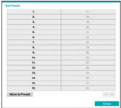
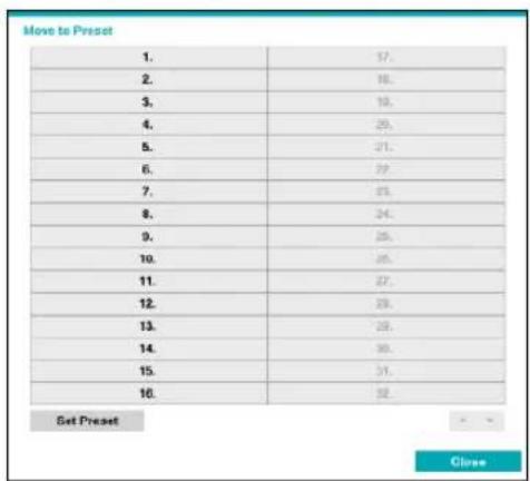
While in PTZ mode, select the PRESET SELECT button on the remote control to display the Move to Preset window. Select a preset to move the current PTZ camera to the selected preset's position.
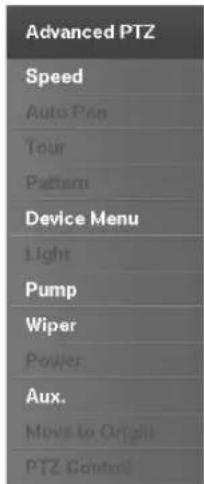
In PTZ mode, select a camera. Clicking Menu button and selecting Advanced PTZ loads the Advanced PTZ screen as shown below. You can load the Advanced PTZ screen also by pressing the MENU button and then Play/Pause button on the front panel. This menu lists Speed, Auto Pan, and other advanced PTZ camera control options available for the camera. Options that are not available for the selected PTZ camera remain inactive.

You can use the mouse to control PTZ cameras. Left-click on the mouse and drag to move the camera in the desired direction and use the mouse wheel to zoom in/out.
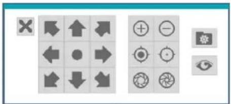
While in PTZ mode, place the mouse pointer close to the bottom edge of the screen to display the PTZ Tools window.
natural_image
Grid of gray square icons with various directional and symbolic shapes (no text or labels)| PTZ Camera Pan and Tilt | |
| Zoom In/Out | |
| Focus Near / Far | |
| IRIS Open / Close | |
| Set / Move to Preset | |
| Device Menu supported by the camera |

•The exact PTZ protocol supported by the camera must be specified in order to use the DVR's PTZ controls.
- Drag and drop to reposition the PTZ Tools window.
- Select the ✗ icon to hide the PTZ Tools window.
Event Monitoring
When an event occurs, the DVR automatically displays the channel linked to the event and shows the icon on the system status area on the bottom of the screen. To use the Event Monitoring feature, navigate to Menu > Display > Main Monitor and enable Event Monitoring. Event Monitoring remains in effect throughout the entire Linked Recording Time. After that, the DVR will return to the previous screen if a new event does not take place. Pressing the Layout or a Camera button before the end of the Linked Recording Time reverts the system to Live mode.
Covert Camera
Use this feature to assign Covert Camera View permissions.
Navigate to Menu > Camera and designate cameras as Covert 1 or Covert 2.
- Covert 1: Hides images from the camera in Live mode but does indicate the camera's title and status via icons.
- Covert 2: The camera is indicated as being inactive. Images from the camera are not shown. Camera title and status icons are not shown.

Users that have a cover Covert Camera View are able to view both images from and status icons for all Covert 1 and Covert 2 cameras.
Status
Refer to the Menu Use on page 20 for basic information on using the Setup menus.
Event Status
This screen displays an overview of all events. When an event occurs, the corresponding channel flashes for 5 seconds.
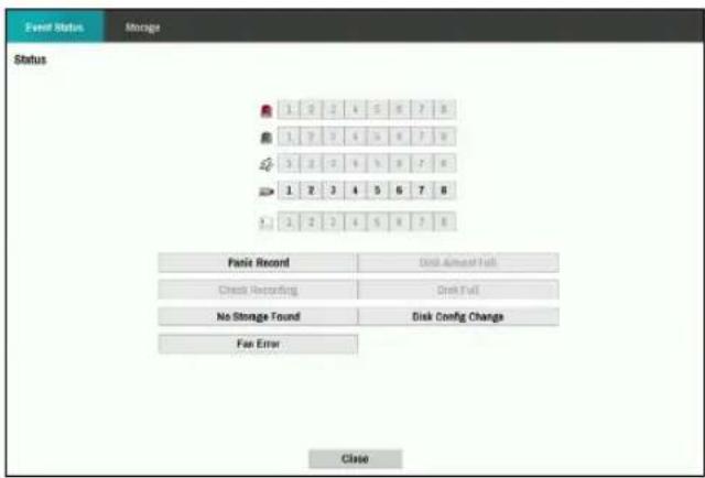
| Alarm-In | |
| Check Alarm-In | |
| Motion | |
| Video Loss | |
| Text-In |
- Panic Record: Displays event status based on current Panic Record status.
- Check Recording: Displays event status based on System Monitoring settings. For more information, refer to the System Event on page 30.
- Fan Error: Event is indicated when the cooling fan cannot reach a certain RPM or fails for longer than 50 seconds.
- No Storage Found: It will be highlighted when no recordable storage device has been found.
- Disk Almost Full/Disk Full: If the storage device is not in Recycle status, event status is displayed when the amount of disk space specified under System Monitoring is reached and when the disk becomes 100% full. For more information, refer to the System Event on page 30.
- Disk Config Change: It will be highlighted when the DVR reboots after the hard disk drive has been replaced.
Storage
Indicates each disk's status.
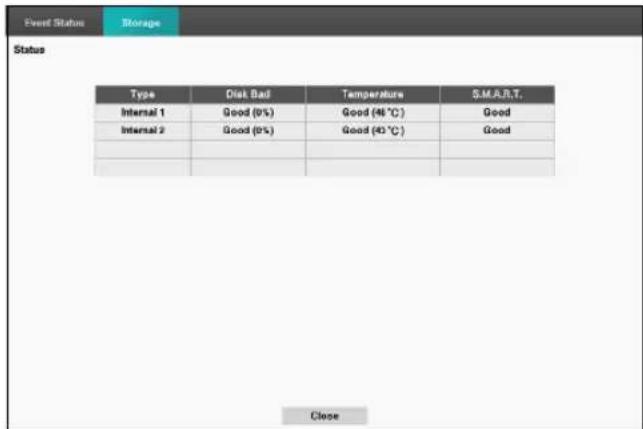
Configure Disk Bad and Disk Temperature settings under Setup > System > System Event.
| Disk Bad | Not Formatted | A disk that has never been used before. |
| Good | • Disk performing normally.• If the HDD is partially damaged, indicates the bad sector percentage. | |
| Error | • If the HDD's bad sector ratio is higher than as designated by the user.• Generates a system event. | |
| Temperature | N/A | Unable to detect the disk's temperature. |
| Good | Operating within normal temperature range. | |
| Bad | • Disk temperature higher than as designated by the user.• Generates a system event. | |
| S.M.A.R.T. | N/A | A disk that does not support S.M.A.R.T. |
| Good | A disk with normal S.M.A.R.T. status. | |
| Bad | A disk with abnormal S.M.A.R.T. status.Possibility of damage within 24 hours. |
Context Menu Access
You can display the ContextMenu window by pressing the MENU button and then PLAY/PAUSE button on the front panel. Alternatively, right-click on the mouse to access the Context menu.
- PTZ: Access PTZ controls.
- Zoom: Zoom in.
- Color Control: Select a channel to display its Color Control window. Adjust the selected camera's brightness, contrast, saturation, and hue settings.
- Menu Control: Adjusts the camera's self-settings.
- Edit Group: Enter to the Edit Group mode in the split screen layout.
• Information: Displays currently connected camera information and recording status.
Video Recording
Video recording will only take place if all the connections are made correctly as per information contained in Part 2 of this operation manual.
For more information on video recording settings, refer to the Record Setup on page 32.
Panic Recording
Select Live or Search menu's Panic Recording Icon or press the Panic Recording button on the front panel or the remote control to commence panic recording on all registered cameras.
To stop Panic Recording, select the Panic Recording icon or press the Panic Recording button again. If the Panic Recording Duration option under Record Setup > General has been configured, Panic Recording will automatically terminate after the specified duration of time has elapsed. For more information, refer to the Record Setup on page 32.

- Panic Recording takes place irrespective of any recording schedule set up by the user.
- Panic Recording ips, Quality, Resolution from Record Setup – General applies to all Panic Recording videos.

Panic Recording will not take place if recording mode is not set to Recycle and the HDD has reached 100% of its capacity.
Audio Recording
If the Record Audio option under Record Setup > General has been enabled the camera will record audio along with video. For more information, refer to the Record Setup on page 32.

Check your local laws and regulations on making audio recordings.
Video Recording Playback
You can play back video recordings by using mouse or remote control.

- Login with an account that has search permission is needed to playback video recordings.
- The initial video playback point in Search mode is the recording's last playback point or the end of the recording data.
- Audio playback of the selected recording is available in full screen mode only.
•Covert protection on cameras also applies to video recording playback.
Remote Control Buttons during Playback
1 Camera Button: Displays the selected recording in full screen.
2 Zoom Button: Allows you to zoom in on a specific area of the recording.
3 Layout Button: Cycle between 2x2, 1x5, 1x7, 3x3 modes.
Context Menu
While in Search mode, right-click on the mouse to access the Context Menu.
- Zoom: Zoom in.
- Edit Group: Enter to the Edit Group mode in the split screen layout.
All Channel Playback
1 Press the Menu button while in Live mode.
2 Select the Search Mode icon and then select All Channels.
3 The selected search mode will be initiated.
For more information on data search, refer to the Part 3 - Search on page 50.
Menu Use
Information contained in this section (Menu Use) applies to all other instructions found throughout Part 3 - Configuration.
Login with an ID that has permission to access the setup menu is needed to access and make changes to the Setup menu.
1 While in Live mode, press the remote control's MENU button or select Live menu > Setup using the mouse.
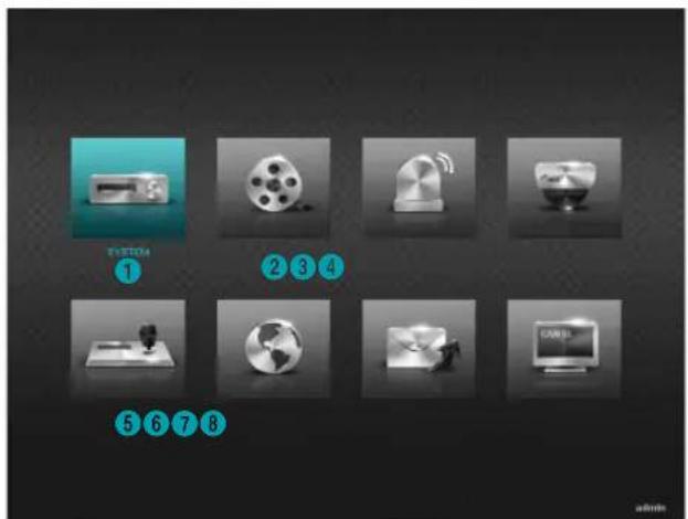
| 1 | System Setup |
| 2 | Record Setup |
| 3 | Event Setup |
| 4 | Camera Setup |
| 5 | Device Setup |
| 6 | Network Setup |
| 7 | Notification Setup |
| 8 | Display Setup |
2 Use the remote control's arrow buttons to select an option and then press the remote control's button or left-click on the option using the mouse.
3 Change the setting and then select Save to save the change.
To apply default settings, select the Default button located on the left bottom corner of the setup window.
Text Input via Virtual Keyboard
Use the remote control's arrow buttons to select a virtual keyboard key and then press the remote control's button or click on the key using the mouse.
![Site 1 2 3 4 5 6 7 8 9 0 - = \ q w e r t y u i o p [ ] a s d f g h j k l ; ' z x c v b n m , . / space OK Cancel](/content/2026/05/1065211/images/302d4b7edcddd11b52ea8fe769538a4b06f2939a8d5bbd35a41514ba1b3fdae5.jpg)
| Toggle case. | |
| Deletes the character to the left of the cursor. | |
| Deletes the character to the right of the cursor. | |
| Converts keyboard. |
Batch Assignment
Certain table-format menus such as the shown in the Camera Setup on page 39 allow you to change the title value. In this case, changing the title value simultaneously changes all other entry values on the same row.
Mouse
Using a mouse makes it easier to configure the settings. A mouse lets you make selections faster and use its wheel to scroll through long menus. You can also use the mouse wheel to increase/decrease numerical values.
System Setup
Refer to the Menu Use on page 20 for basic information on using the Setup menus.
General
This Setup menu contains general system options.
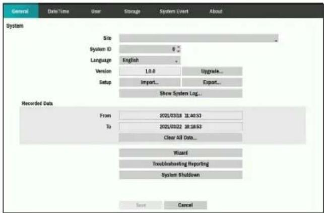
- Site: Used to enter a description about the system's installation site (no description by default). You can edit the information using the virtual keyboard.
- System ID: Used to identify the DVR apart from other DVRs. System ID is also used to control the DVR with the remote control and identify the unit when it is connected with other DVRs through the RS485 port.

The default System ID is 0 and can be changed to a value between 0 and 99. The System ID can also be entered using the virtual keyboard.
• Language: Choose a language.
- Version: Indicates the software version.
Part 2 - Configuration
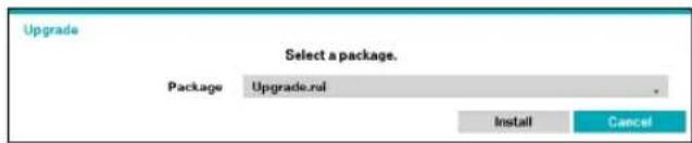
- Upgrade: Upgrade the system. Selecting the USB port displays the USB search window. You will then be able to select an upgrade package and upgrade the system.

- The ".rui" indicates that the file is for software upgrades.
- If an upgrade attempt fails, an upgrade failure message will be displayed. Refer to Error Code Types in the installation manual for more details.
- Setup: Exports current DVR settings or imports existing settings.
- Import: Decide whether to import network settings as well. If you do not wish to change the current network settings, do not select Include Network Setup.

Selecting Setup Import does not change the settings below.
• Time-related settings (Date/Time, Time Zone, and Use Daylight Saving Time)
- Export: Exports the current system settings to a storage device connected to the system's USB port. You can designate a File Name for the export file.

For USB flash memory devices, the DVR supports the FAT16 and FAT32 files format.
• Show System Log: Displays a searchable list of 5,000 most recent system log entries. For more information on types of system log entries, refer to the System Log Types in the installation manual. The 📋 icon appears next to log entries originating from a remote source. To export the system log, select the Export at the bottom of the screen and then designate a file name.
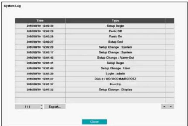
- To export the system log information, connect the USB device to the DVR. Click Export. Select USB Storage. A virtual keyboard allows you to enter the file name. Selecting Export will save the log information in .txt file format on the USB device.


In order to display the system_log.txt file, you must use the correct character encoding settings and use a fixed-width font.
- Clear All Data: Erases all recording data. Selecting Clear All Data displays a confirmation window. Select Clear to proceed.

- Before you perform Clear All Data, make sure you are not accidentally deleting important data. Erased data cannot be recovered.
- Clear All Data does not affect the system log. Instead, the Clear All Data event will be added to the log.
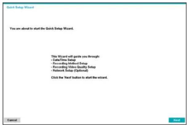
- Wizard: Lets you configure basic settings required for operating the system.
1 Select the desired Setup Wizard option and click Next.
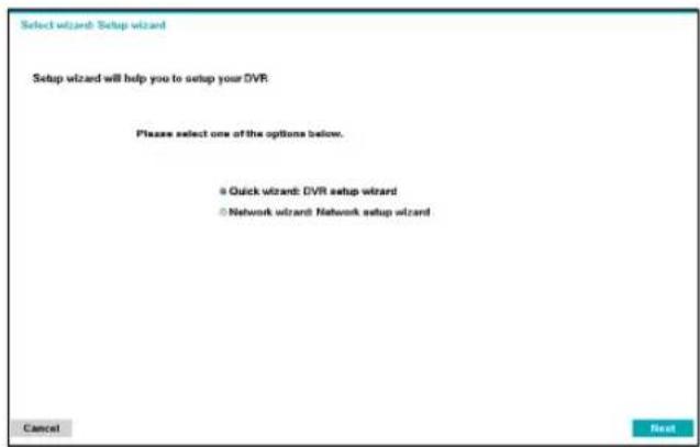

Select Cancel from any of the Wizard screen to cancel the setup process and return to the main setup menu.
Quick Wizard
1 Select Quick Wizard.
2 Specify the current date and time and then click Next.
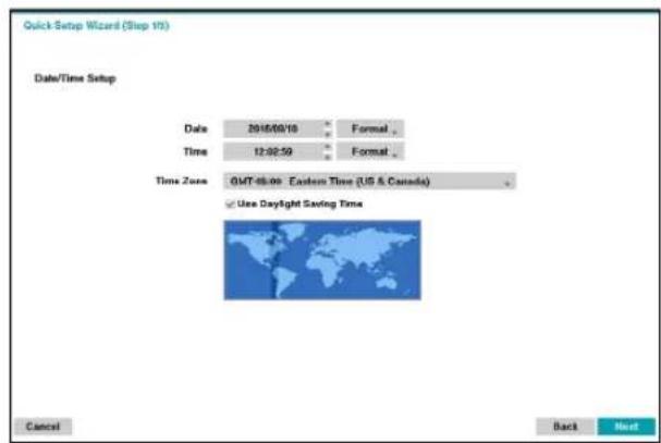

- The new date and time settings will only be applied after clicking Next.
- For more information on date and time settings, refer to the Date/Time section under System Setup on page 21.
Part 2 - Configuration
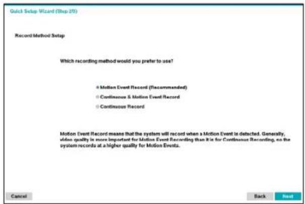
3 Choose the desired Recording Method and click Next.
4 Choose the desired Recording Quality and click Next.
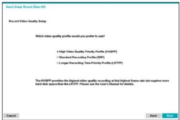
- Recording ips, quality, resolutions used under each recording method and record video quality setting are as follows:
| High Video Quality Priority Profile | Standard Recording Profile | Longer Recording Time Priority Profile | |
| Motion Event Record | Very high, Very high, 30 ips | High, Very High, 15 ips | Standard, High, 5 ips |
| Continuous & Motion Event Record | Very high, Very high, 30 ips (Time/Event) | Time: High, Very High, 15 ips Event: Very High, Very High, 30 ips | Time: Standard, High, 5 ips Event: High, Very High, 15 ips |
| Continuous | Very high, Very high, 30 ips | High, Very High, 15 ips | Standard, High, 5 ips |
5 Click Finish to exit Quick Wizard.
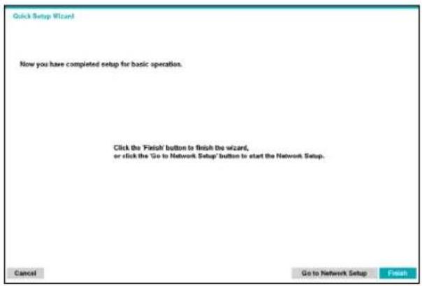

Higher recording quality uses up more disk space.
Network Wizard

After exiting from Quick Wizard, you can click Go to Network Setup and set up the network with Network Wizard.
1 Select Network Wizard.
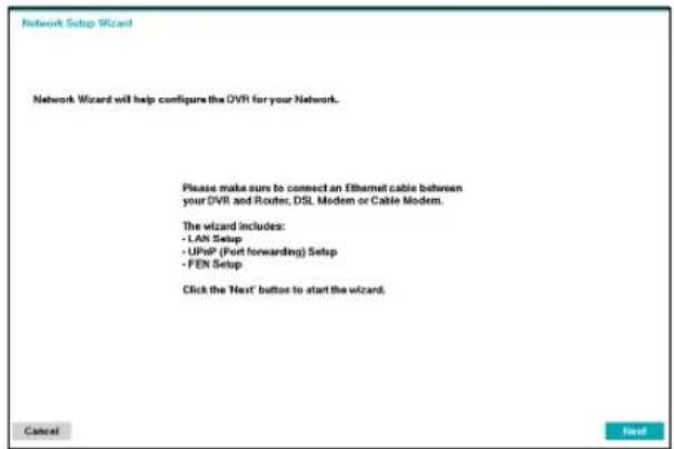
2 Specify whether the system is connected to the Internet and click Next.
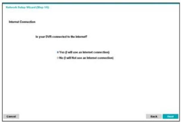

If you have chosen No, wait for the test to finish and then click Finish to exit Network Wizard.
3 Select Network Configuration and then click Next. Select either Auto Configuration or Manual Configuration and then click Test to test the system's current network configuration.
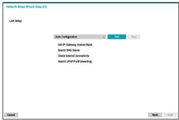

- This test must be performed before proceeding to the next step.
- If the DVR is on a network connected to a network that has a DHCP server, selecting Auto Configuration retrieves LAN settings such as IP and DNS addresses automatically. Selecting Manual Configuration, on the other hand, lets you specify the settings manually.
- UPnP support device not found. If this error message is displayed, check to see if the IP router (or NAT) supports UPnP and if UPnP has been enabled. For more information about the router's UPnP function, refer to the router's operation manual.
Part 2 - Configuration
4 Enter in the FEN Name field the DVR name to be registered on the FEN server and then click Check to check its availability.
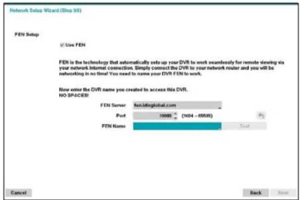

- The FEN name you register on the FEN server will be a unique name used to identify the DVR. Once registered, the name can be used to access the DVR directly from clients such as the IDIS Center. Check the name's availability to complete the registration process. The Finish button will then become activated.
- You will be prompted with an error message if you do not enter a name for the DVR or enter a name already registered on the FEN server.
- Depending on the network environment, FEN services may not be active and therefore prevent the DVR from connecting to the network. In this case, you will need to manually configure the ports. For more information on port configuration, refer to Network Setup on page 42.
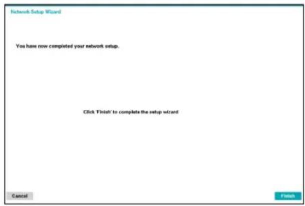
5 Click Finish to exit Network Wizard.
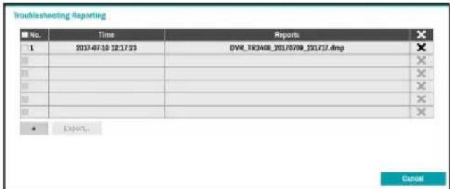
- Troubleshooting Reporting: Generates a report to troubleshoot any issues, and exports the report.
- System Shutdown: Shuts down the system. When prompted, select System Shutdown.
Date/Time
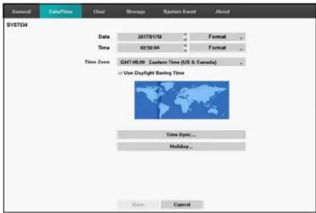
- Date: Used to change the system's date setting.
- Time: Used to change the system's time setting.
- Date Format/Time Format: Used to change the system's date and time formats.
- Time Zone: Used to designate the system's time zone.

Refer to the map displayed on the screen and change the time zone using the mouse or the arrow buttons.
- Use Daylight Saving Time: Enables DST correction.
- Time Sync.: Select a time server for the system to synchronize with.
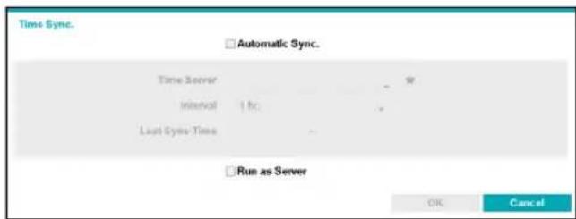
1 Select Automatic Sync.
2 Enter the Time Server's IP address or domain name or select ★ and then choose a server from the list of registered time servers.
3 Specify the server synchronization Interval.
4 Select OK to apply and exit.

- If you have configured the DNS Server setting under Network - IP Address, you can enter the time server's domain name instead of its IP address.
- Selecting Run as Server sets the current DVR as a time server for other DVRs within the system.
- Holiday: Designate holidays. On specified holidays, recording takes place according to the holiday recording schedule specified under Record Schedule.
1 Select the + button at the bottom of the window.
2 Select a date.
3 Select OK to apply and exit.
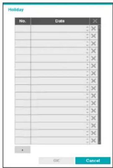

Select the icon to delete the existing holiday date.
User
Use this option to register users and assign permissions.
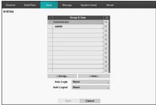
1 Select + Group and enter a group name. A group name can be up to 15 characters in length.
2 Specify the group's permission settings. For more information on permission settings, refer to the Group Permissions on page 29.
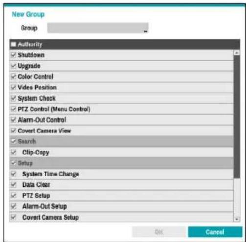
3 Select + User and then enter a user name.
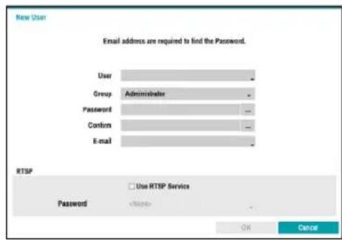
4 Select a group for the user and then enter a password. The password can be 8\~16 characters in length and may include numbers.
5 Select OK.
6 Configure Auto Login and Auto Logout settings.
7 Select Save to exit.

- Group names, user names, and passwords can be entered using the virtual keyboard. For more information on using the virtual keyboard, refer to the Text Input via Virtual Keyboard on page 20
• To delete a registered user or group, select the icon on the right of the corresponding user/group. Group Administrator and User admin cannot be deleted.
- Select the ✗ icon next to Group & User on the top of the screen to delete all groups and users except Group Administrator and User admin simultaneously.
- A password entry is required to edit existing groups and users.
- Group Administrator's permissions cannot be changed.
- With the User admin account, only the password can be changed.
- When the system starts up, it will automatically log into the account designated under Auto Login.
- The system will automatically log out of the account if the duration of inactivity specified under Auto Logout.
Group Permissions
| System Shutdown | May shutdown the system from the system menu. | |
| Upgrade | May upgrade the system from the system menu (System Setup). | |
| Color Control | May adjust each camera's brightness, contrast, saturation, and hue settings. | |
| Video Position | May adjust the video position in left/right directions. | |
| System Check May view System Check results. | ||
| PTZ Control (Menu Control) | May control PTZ cameras. | |
| Alarm-Out Control | May reset in the event of an alarm-out.Alarm-outs can be reset by pressing the Alarm button on the device or selecting the Alarm-Out Control button on the remote program. | |
| Covert Camera View | May access covert cameras in Live and Search modes. | |
| Search | Clip Copy | The user who has permission for Clip Copy can perform Clip Copy. If the user does not have permission, Clip Copy is not allowed but only search is allowed. |
| Setup | System Time Change | May change the system's date and time settings. |
| Data Clear | May clear data stored in the system. | |
| PTZ Setup | May configure PTZ settings. | |
| Alarm-Out Setup | May configure alarm-out settings. | |
| Covert Camera Setup | May configure convert camera settings. | |
| Privacy Masking Setup | May configure privacy masking settings. | |
| Record Setup | May configure recording settings. | |
| Setup Import | May import previously saved DVR settings. | |
| Setup Export | May export current DVR settings. |
Storage
Use this option to configure storage settings.
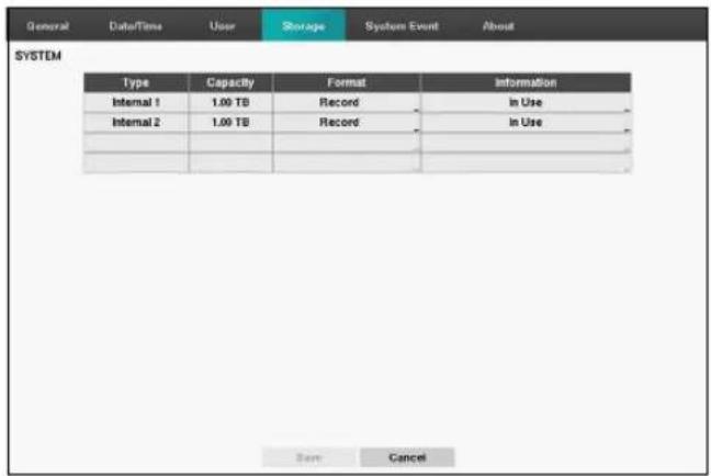
- Type: Indicates the type of the installed disk.
- Capacity: Indicates the disk's capacity.
- Format: If the disk has been formatted, indicates either Record or Not Using. If you have connected an unformatted storage device, the Use As value will be indicated as Not Formatted.
- Information: Indicates if the disk is being used for recording purposes. Disks that were used in different systems will show up as Other. Select Information to check the saved data's time information or select Delete to erase the data.

- Select Format to prepare the disk as a storage for data recording.
- Disks formatted with Use As set to Not Using will not be used for data recording.
•This DVR supports SATA2 HDDs.
System Event
Use this option to configure Monitoring settings.
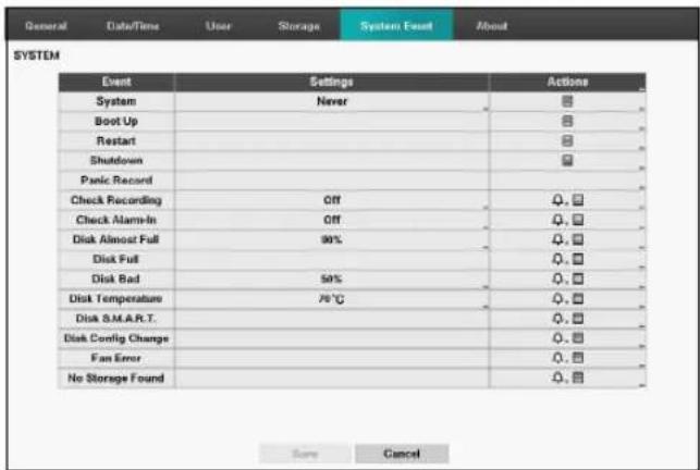
- Settings: Configure when and what the system should monitor for.
- Actions: Configure alarm-out (DVR alarm-out channel, DVR beep) and notification (email, LAN1 through 5, push, alert window) settings.
Monitoring Options
| System | Define monitoring times. If self-diagnosis is not performed on a regular basis, the system will assume an error. |
| Bootup, Restart, Shutdown | Define bootup, restart and shutdown actions. |
| Panic Record Define | panic recording actions. |
| Check Recording | The system will assume an error if the system has been scheduled to record normally but recording does not take place during scheduled intervals. Select Schedule On and then configure the days of the week, times, and monitoring interval. Select the button on the bottom left of the screen to add a schedule. Select icon to delete the schedule. Select Schedule On and then configure the days of the week, times, and monitoring interval. Select the button on the bottom left of the screen to add a schedule. Select icon to delete the schedule.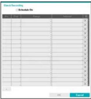 |
| Check Alarm-In | The system will assume an error if the alarm-in status does not change during the specified monitoring interval while alarm-in is active. |
| Disk Almost Full | Generates an event if the disk reaches the specified capacity (80% to 99%). |
| Disk Full | Generates an event when all disks reach their maximum capacity. |
| Disk Bad | Generates an event when the specified percentage of the disk becomes damaged. Set to between 10% and 90% in 10% intervals. |
| Disk Temperature | Specify the threshold temperature. Once any disk reaches this threshold, the system will issue an alert. |
| Disk S.M.A.R.T. | Monitors disks that support S.M.A.R.T. and notifies the user if a disk error is detected. |
| Disk Config Change | It will be highlighted when the DVR reboots after the hard disk drive has been replaced. |
| Fan Error | Notifies the user when the fan inside the system malfunctions. |
| No Storage Found | It will be highlighted when no hard disk drive has been connected. |

- For system events, only an e-mail notification of actions can be selected.
- In order to use the Notify(Callback) feature, the DVR must be registered to the remote program on the receiving PC's end.
About
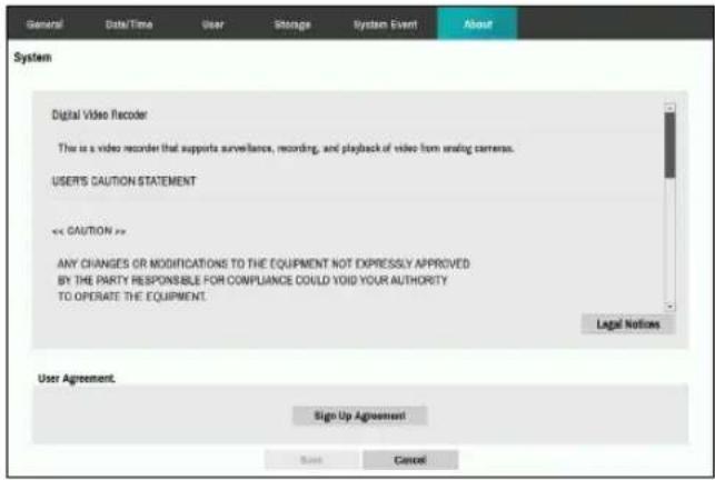
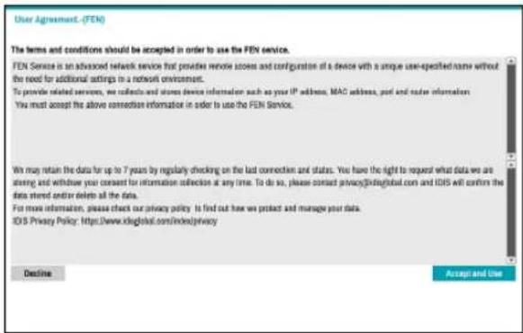
- User Agreement: Click Accept and Use to agree to retaining the device data, and use the service.
Record Setup
Refer to the Menu Use on page 20 for basic information on using the Setup menus.
General
Configure general recording settings.
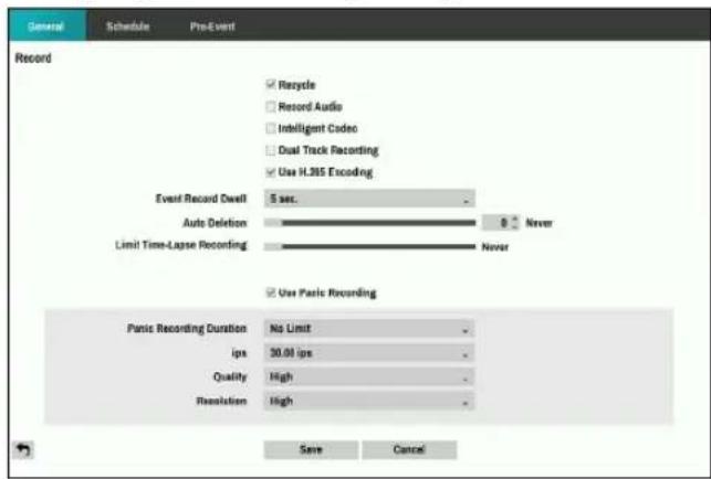
- Recycle: When the recording disks become full, the system overwrites existing data with new data, starting with the oldest first. If Recycle is disabled, recording will simply stop when the recording disks reach their maximum capacity.
- Record Audio: The camera will record audio along with video.
- Intelligent Codec: Automatically lowers bitrate when any motion is not detected.

The bitrate does not decrease when using intelligent codec for pre-event recording.
- Dual Track Recording: Schedule with a lower quality and lower resolution is additionally recorded. Additional recorded video can be played back in real-time as a split screen. During dual recording, the recording icon is displayed as 🧿️.

-
If the recording quality setting is Very High during dual recording, the recording operates under High quality.
• Dual recording does not operate for SD input. -
Use H.265 Encoding: Check to use H.265 codec, and uncheck to use H.264 codec.
- Event Record Dwell: If linked recording is designated as an event-triggered action, recording takes place for the duration specified under this setting.
- Auto Deletion: Configure this option to delete recording data automatically after the specified number of days has elapsed. Select between 1 day and 999 days.

To disable Auto Deletion, select Never. If enabled, recording data will be stored on the DVR for the specified number of days and then deleted automatically. Expired recording data are deleted automatically at midnight and will be deleted even if the system reboots or the Auto Deletion setting has been changed.
- Limit Time-Lapse Recording: You can store event recording data for longer. If you do not wish to use Limit Time-Lapse Recording, select Never. This function is activated when data has been stored for longer than as configured because the recording disk has sufficient capacity and saves new data by overwriting Time Lapse Recording data that are older than as specified under Recycle mode.

- If the recording stored on the disk is shorter than the duration specified under Limit Time-Lapse Recording, the older of Event Recording or Time Recording data is deleted first.
-
The system's recording time may change depending on recording quality, resolution, motion, and other configurations made by the user. The duration specified under Limit Time-Lapse Recording may not be guaranteed in certain situations.
-
Use Panic Recording: Enable/disable Panic Recording.
- Panic Recording Duration: Disable Panic Recording automatically. Select between 5 mins and 1 hr. If you do not wish to disable the feature automatically, select No Limit.
- ips: Allow you to set the images per second for Panic recording.
• Quality: Allow you to set the recorded image quality for Panic recording. You can select from: Very High, High, Standard and Basic. - Resolution: Allow you to set the recorded image resolution for Panic recording. You can select from: Very High, High, and Standard.
Schedule
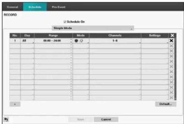
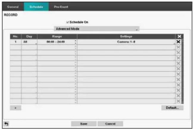
Disabling Schedule On suspends schedule recording regardless of the schedule and displays the 🔒 icon on the upper left corner of each camera screen. Pressing the Panic Record button displays the 🔒 icon and commences panic recording.
Set Record Schedule mode as Simple Mode or Advanced Mode. Advanced Mode allows you to configure a unique recording schedule for each event.
Select the ✗ icon to delete a schedule.

- Changing the recording schedule mode suspends all active event-linked actions.
- Select the + button on the bottom left of the screen to add a schedule. Select Day to specify the Day setting or select All. Select Scope to specify the time frame.
Simple Mode Options
- Mode: Select No Record, Time, Event, or Time & Event.
| No Record | Unless the Panic Record button is pressed, no recording will take place during the scheduled time frames on the scheduled days. |
| Time | Theicon appears on the upper left corner of the screen. Theicon appears at scheduled times to indicate recording is in progress. |
| Event | Theicon appears on the upper left corner of the screen. Theicon appears when the specified event occurs to indicate recording is in progress. If Pre-Event is enabled, theandicons appear when recording is not in progress, or theandicons appear when an event occurs and recording is in progress. If Pre-Event is enabled, theandicons appear when recording is not in progress, or theandicons appear when an event occurs and recording is in progress. |
| Time & Event |  icon appears on the upper left corner of the screen and recording commences as per the ips, Quality,Resolution selected for time under Setup. When an event occurs, the icon icon appears on the upper left corner of the screen and recording commences as per the ips, Quality,Resolution selected for time under Setup. When an event occurs, the icon  ges intoicon and recording commences as per the ips, Quality, Resolution selected for events under Setup. ges intoicon and recording commences as per the ips, Quality, Resolution selected for events under Setup. |
- Channel: Select which cameras to apply the schedule to.
- Settings: Select to configure default values for Time Lapse and Event Recording modes.
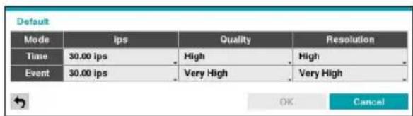
Advanced Mode Options
Select to configure event types.
- Type: Event-specific and time recording icons are as follows:
 | Time Lapse (Time) |  | Video Loss |
| [ATWS] | Alarm-In Text-In | [SYWY] | |
 | Motion Detection |
- ips: Allow you to set the images per second for Time and Event recording.
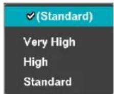
- Quality: Allow you to set the recorded image quality for Time and Event recording. You can select from: Very High, High, Standard and Basic.
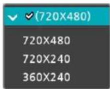
- Resolution: Allow you to set the recorded image resolution for Time and Event recording. You can select from: Very High, High, and Standard.
- Dwell: Specify how long to record for after a corresponding event occurs.

• Upper-tier schedule's settings apply to unconfigured channels.
- If multiple events take place on a specific channel and different ips, Quality, Resolution, and Dwell Time settings apply, highest settings apply to all event-linked recordings.
•The resolution can be set up at a time for each event or separately for each channel of an event. When setting up at a time for each event, the following options are available: Very High, High and Standard. Selecting Very High, the highest resolution will be applied. Selecting Standard, the lowest resolution, and selecting High, the other resolution will be applied. When setting up separately for each channel of an event, you can select any resolution supported by the camera mode (720, 960, HD, Full HD, 3M, 4M, 5M).
Event
720 Mode
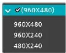
960 Mode HD Mode
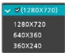
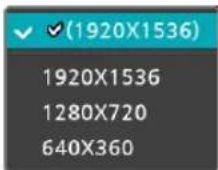
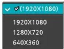
Full HD Mode 3MP Mode
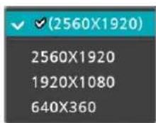
4MP Mode 5MP Mode
Pre-Event
When an event occurs, enabling this option includes the specified duration prior to the event in the event-triggered recording.
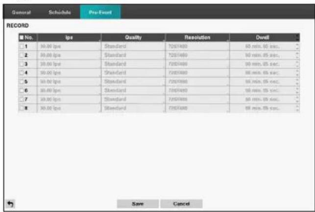
• No.: Select which cameras to apply Pre-Event to.
- ips, Quality, Resolution: The image quality can be selectable from Very High, High, Standard and Basic, and image resolution can be selectable from Very High, High, and Standard.
- Dwell: Specify the duration of pre-event recording data.

- If no event mode schedule exists in the schedule, a warning message prompting you to add an event mode schedule will be displayed.
- The warning message will appear even in Time & Event mode.
Event Setup
Refer to the Menu Use on page 20 for basic information on using the Setup menus.
Motion
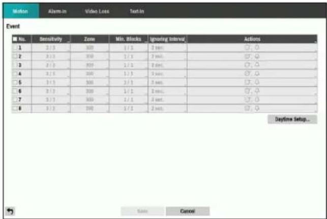
- No.: Select which cameras to apply Motion Detection to.
- Sensitivity: Set daytime and nighttime sensitivity settings between 1 (Low) and 5 (High).
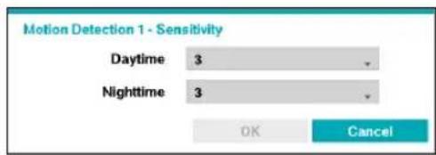
• Zone: Define the motion detection block.

natural_image
Grid of white squares on a black background, no text or symbols presentUse the remote control's arrow buttons to move the block selection window up, down, left, and right. The selection window consists of 8 blocks per row. Select/deselect individual blocks using the Camera buttons. You can use the mouse to drag the zone and then select, clear, or reverse the selection.
From the zone selection screen, press the button on the remote control or right-click on the mouse to open up the Zone Setup menu.
| Select |
| Clear |
| Reverse |
| Select All |
| Clear All |
| Reverse All |
| OK |
| Cancel |
- Select: Confirm the block selection in the selection window.
– Clear: Clear the block selection in the selection window. - Reverse: Clear the blocks selected within the selection window and select all unselected blocks within the selection window.
- Select All: Select all blocks.
– Clear All: Clear all block selections. - Reverse All: Clear all selected blocks within the screen and select all unselected blocks within the screen.
- OK: Save the changes and exit the menu.
- Cancel: Exit the menu without saving the changes.
- Min. Blocks: Motion needs to be detected in more than the specified number of blocks in order to trigger a Motion Detection event. You may select a value between 1 and the number of blocks selected under Zone for daytime and nighttime, each.
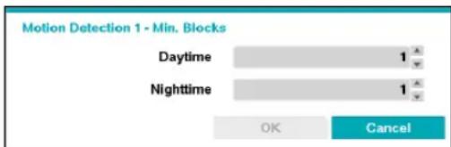
- Motion Ignoring Time: The system does not produce event log entries or issues remote notifications regarding motion detected during the specified time following the initial motion detection. Set a value between 1 sec and 10 secs or choose Never.

Motion Ignoring Time does not affect motion detection recording.
- Actions: Specify which actions to take when motion is detected.
- Record: Specify which cameras to begin linked recording on when an event occurs. If the schedule is set to Event or Time & Event mode, the selected cameras will begin linked recording when an event occurs.
- Alarm-Out: Designate event-triggered alarm-out channels and beeps.
- Notify: Configure to be notified of events by Mail, LAN1 through 5, Push, and/or Alert Window.
- PTZ: Moves the PTZ camera to a specific preset position when an event occurs.

In order to use the Callback feature, the DVR must be registered on the remote program.
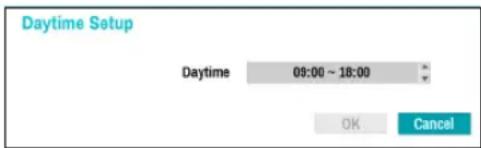
- Daytime Setup: Specify when daytime starts and ends. Adjust the time frame in 15-minute increments. Times outside the specified range will be assumed as nighttime by the system.
Alarm-In
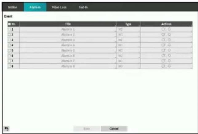
• No.: Enable / disable alarm-ins.
• Title: Use the virtual keyboard to enter titles.
- Type: Change the alarm-in type.
- Actions: Specify which actions to take when Alarm-In is detected.
- Record: Specify which cameras to begin linked recording on when an event occurs. If the schedule is set to Event or Time & Event mode, the selected cameras will begin linked recording when an event occurs.
- Alarm-Out: Designate event-triggered alarm-out channels and beeps.
- Notify: Configure to be notified of events by Mail, LAN1 through 5, Push, and/or Alert Window.
- PTZ: Moves the PTZ camera to a specific preset position when an event occurs.

In order to use the Callback feature, the DVR must be registered on the remote program.
Video Loss
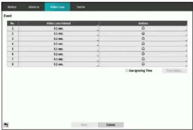
- Video Loss Interval: The system does not produce event log entries or issues remote notifications regarding video loss detected during the specified time following the initial video loss detection. Set a value between 0.1 sec and 15 secs or choose Never.
-
Actions: Specify which actions to take when a Video Loss event occurs.
-
Record: Specify which cameras to begin linked recording on when an event occurs. If the schedule is set to Event or Time & Event mode, the selected cameras will begin linked recording when an event occurs.
- Alarm-Out: Designate event-triggered alarm-out channels and beeps.
- Notify: Configure to be notified of events by Mail, LAN1 through 5, Push, and/or Alert Window.
- PTZ: Moves the PTZ camera to a specific preset position when an event occurs.

In order to use the Callback feature, the DVR must be registered on the remote program.
- Use Ignoring Time: Select Time Setup to specify the video loss detection ignore time. Video loss detection will be disabled during the specified time frame.
Text-In
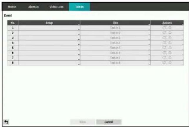
- Setup: Configure text-in devices.
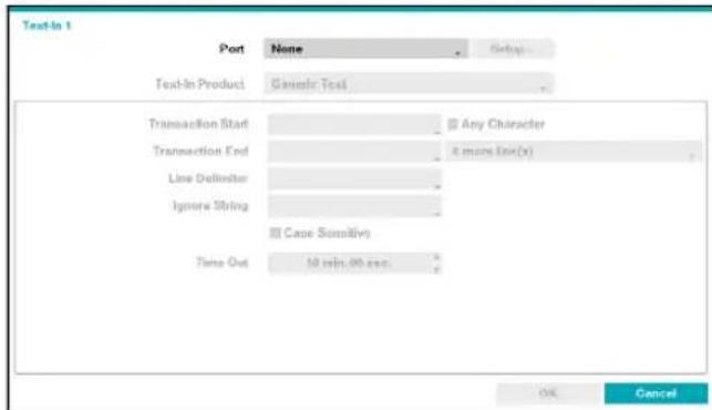

- It's possible to batch configure all text-in devices with the exception for port settings.
- An influx of large amounts of text-in data from multiple channels can hinder system performance.
- Text-In Product: The setup window is updated so that the portion below the port setting matches the corresponding text-in device. Displayed screenshot illustrates Generic Text settings.
- Transaction Start: Once Transaction Start has been designated, the system will recognize the specified string as the beginning of a transaction. You can choose the Any Character setting. Under this setting, any character will trigger the system into recognizing the start of a new transaction.
-
Transaction End: Once Transaction End has been designated, the system will recognize the specified string as the end of a transaction. Select 0 more line(s) next to Transaction End and specify a value between 1 and 10. The system will recognize the specified Transaction End string plus the number of lines as being the end of a transaction.
-
Line Delimiter: Designate a string to mark the end of a line. You can enter control strings by selecting and then entering , followed by a letter. For example, Carriage Return is M and Line Feed (new line) is J.
- Ignore String: Specify a string to ignore from transaction records.
- Case Sensitive: Ignores case in strings designated under Transaction Start, Transaction End, Line Delimiter, and Ignore String.

Case Sensitive does not apply to control strings.
- Time Out: Once Time Out has been enabled, the system will assume the end of a transaction if no new string is entered within the specified duration of time. Select between 5 secs and 15 mins.
Selecting RS-232, RS-485, USB-Serial 1 through 8, or LAN 1 through 4 as the port activates the Port Setup button. Select Setup and configure the Baud Rate, Data Bit, Stop Bit, and Parity settings.

- If any one of LAN1 through 4 has been selected as the port, select the Port Setup button and configure the network port setting.
- If using a USB-serial port, the Text-In feature may malfunction if the USB cable is removed while the system is in operation.
• Title: Designate a name for the text-in device.
- Actions: Specify which actions to take when text-in is detected.
- Record: Specify which cameras to begin linked recording on when an event occurs. If the schedule is set to Event or Time & Event mode, the selected cameras will begin linked recording when an event occurs.
- Alarm-Out: Designate event-triggered alarm-out channels and beeps.
- Notify: Configure to be notified of events by Mail, LAN1 through 5, Push, and/or Alert Window.
- PTZ: Moves the PTZ camera to a specific preset position when an event occurs.

In order to use the Callback feature, the DVR must be registered on the remote program.
Camera Setup
Refer to the Menu Use on page 20 for basic information on using the Setup menus.
General
Enable/disable the covert view and rename cameras.
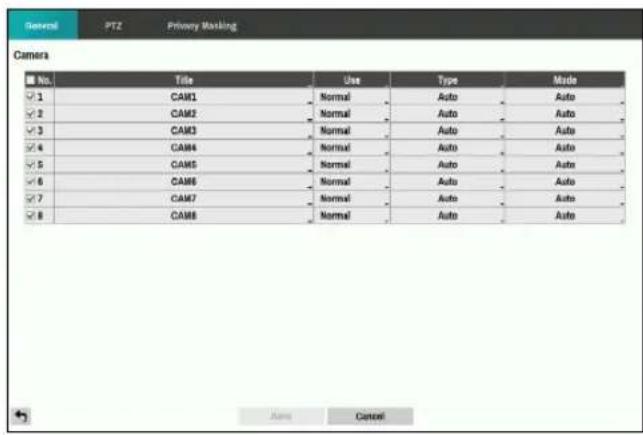
- No.: Turn the camera number On or Off.
• Title: Edit the camera's name.
• Use: Set the camera as Normal, Covert 1, or Covert 2.
Live images and video recordings from cameras that have been set as Covert 1 or Covert 2 will not be available to users who do not have covert camera access. Setting a camera as Covert 1 hides its images but does display OSD information about the camera. Setting a camera as Covert 2 hides its images as well as OSD information about the camera as if it has been deactivated completely.
- Type: Select the type supported by the camera among Auto, SD, HD-TVI and AHD. Selecting Auto allows the DVR to automatically detect the type supported by the camera.
- Mode: Select the width resolution supported by the camera among Auto, 720, 960, HD, Full HD, 3MP, 4MP and 5MP. Selecting Auto allows the DVR to automatically detect the width resolution supported by the camera.

When selecting Auto, the 720, HD, Full HD, 3M, 4M and 5M mode are supported. The input resolution is applied without rebooting the system. If the camera's width resolution is 960 and Mode is set to Auto, 720 mode will be applied.
PTZ

You will only be able to set up PTZ devices if the PTZ port is set to RS232 or RS485.
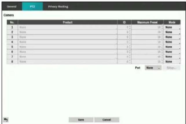
- Product: You can select the PTZ camera you wish to configure.
- ID: You can assign IDs to each camera by highlighting the box under the ID heading. Change the number by highlighting it and using the Up and Down arrow buttons to increase and decrease the number. The PTZ ID number can be set from 0 to 256.
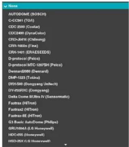
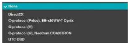
- Mode: Select None, UTC, RS232, or RS485. UTC is only used for HD, Full HD, 3M, 4M and 5M cameras.

UTC may not work properly depending on the type of camera.
Part 2 - Configuration
- You will need to connect the camera to the RS232 or RS485 connector on the back of the DVR following the camera manufacturer's instructions.
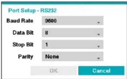
Configure the port's setting based on the PTZ camera manufacturer's instructions.
Privacy Masking
Configure privacy masking zone for Live and Recording screen.
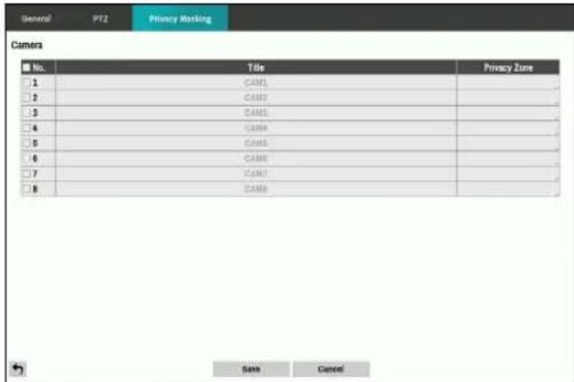
• No.: Turn on/off the camera number.
- Privacy Zone: Display the full screen live mode of the channel, and you can configure the privacy zone area by dragging on the area with the mouse (The privacy masking zone can be configured up to 4 areas).
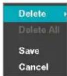
- Delete: Delete the selected privacy masking area.
- Delete All: Delete the all privacy masking area.
- Save: Save the changes and exit the privacy masking area options screen.
- Cancel: Exit the privacy masking area options without saving the changes.
Device Setup
Refer to the Menu Use on page 20 for basic information on using the Setup menus.
Audio
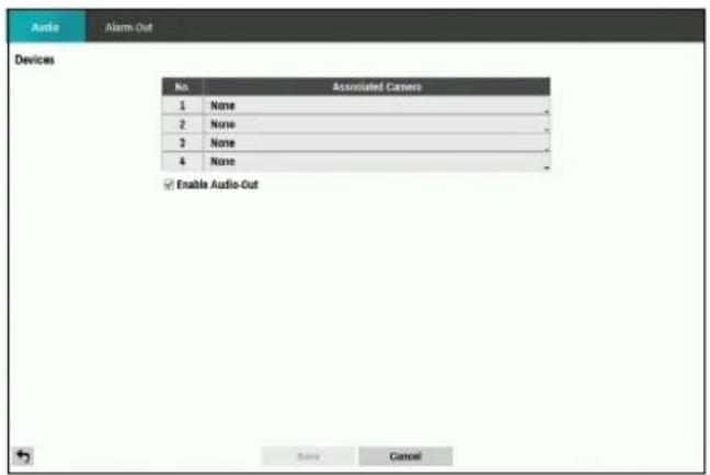
The DVR can record up to four audio inputs. A list of cameras appears, and you can select which camera you want associated with that audio input.
Alarm-Out

Select the + icon at the bottom left corner of the screen to add a schedule.
You can apply different schedules for different Days of the week.
Select ✗ icon to delete the schedule.
- Dwell Time: Select a value between 5 secs and 15 mins as the alarm-out duration.
• Title: Designate a name for the alarm-out.

- Reverse Relay: Reverse the alarm-out type connected to the DVR rear panel (NO→NC).
- Range: Change the schedule time frame.
• Mode: Select Event, On, or Off.
| Event | Generates an alarm-out when an event occurs. |
| On Alarm-out is always on. | |
| Off | Alarm-out is always off. |
- Channels: Configure alarm-out port and beep settings.
Network Setup
Refer to the Menu Use on page 20 for basic information on using the Setup menus.
General
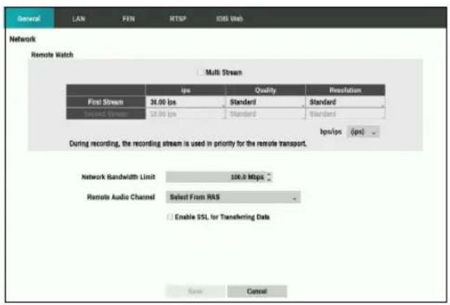
- Multi Stream: Supports more than one stream. Configure to use different streams in layout mode or channels in IDIS Center Client.

During playing, the transfer speed can be low.
- bps/ips: Select the Transfer Speed from 1Mbps to 100Mbps and the unit of measure for the transfer speed between: bps and ips. The available value differs depending on the quality and resolution settings.
• Quality: Select the Quality from: Very High, High, Standard and Basic.
- Resolution: Select the Resolution from: Very High, High and Standard. During recording, the recording stream is applied to the remote transfer in priority.

The higher Quality and Resolution settings require higher Transfer Speed settings. The transfer speed you set is the maximum speed. Depending on the network environment, this speed may not be achieved.
- Network Bandwidth Limit: Configure the bandwidth to limit.

If you configured the Network Bandwidth Limit, the live video may not be displayed smoothly in a remote program.
- Remote Audio Channel: Transmits the selected channel's audio to the remote program. Select Select From Client to stream audio of the channel selected on the remote program.

Audio skipping and sync issues can occur under poor network conditions.
- Enable SSL for Transferring Data: Applies SSL (Secure Sockets Layer) protection on remote viewing and recording data transmissions.

- If using the SSL feature, it will not be possible to connect to the DVR from a remote program or a network keyboard that does not support SSL.
- Changing the SSL setting temporarily severs all remote connections to the DVR in order to apply the change.
- This product contains content developed by OpenSSL Project for use in Open SSL Toolkit (http://www.openssl.org/).
LAN
Designate the IP address type as Manual or DHCP.
Manual
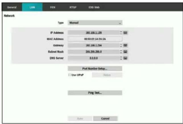
- Set Type to Manual.

Manual lets you configure related settings manually. Configure IP Address, Gateway, and Subnet Mask settings manually using the remote control's arrow buttons or the mouse wheel.
- DNS Server: Enter the DNS server's IP address. The IP address can also be entered using the mouse wheel.
- Port Number Setup: Change the numbers by highlighting them and using the Up and Down arrow buttons to increase or decrease the number. The factory default Port settings are: 8200(Remote Admin), 8201(Remote Callback), 8016(Remote Watch), and 10019(Remote Search).

You will need to get the appropriate Port Numbers for each IDIS Center and IDIS Web related program (Admin, Callback, Watch and Search) from your network administrator.
To use the UPnP (Universal Plug and Play) feature, select Use UPnP. If using an IP router (or NAT), UPnP service allows the device to automatically forward the port to the DVR.

- This port is used to access a port that has a private IP address.
• In order to use the UPnP service, the IP router (or NAT) must support UPnP port forwarding and have the relevant options enabled.
- Port number cannot be changed with Use UPnP selected.
- Status: Indicates the number of the port forwarded by the IP router (or NAT) to the DVR via UPnP service.
- Ping Test: Select to test the current LAN settings you made.
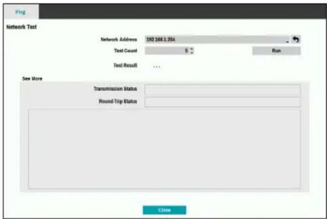
1 Enter the address of the DVR to test.
2 Adjust the frequency of the ping test.
3 Select Run to do the test. The test result is displayed.
4 Select Close to exit.

- If using a firewall, select Change Port to change the port number to one that is permitted by the firewall.
- Changing the port temporarily severs the DVR's remote connection.

Remote point IP and port settings on the remote program must also be changed in order for it to connect to the DVR.
DHCP
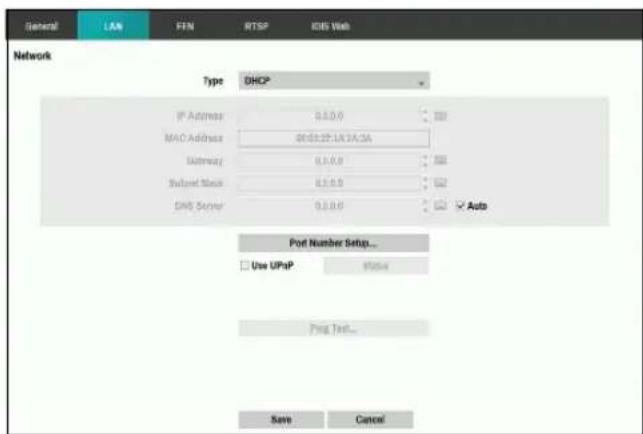
Select DHCP and then Save to retrieve IP address and other network settings automatically from the DHCP server. Once the network settings have been retrieved, the DVR's current IP address is displayed in the IP Address field.

- It may not be possible to retrieve the IP address if there is no DHCP server. If this is the case, contact your network administrator.
- With DHCP, the DVR's IP address might change with each startup.

There is a limit to the number of users allowed to connect remotely at the same time. Contact the service center for more information.
FEN
If using a dynamic IP address, FEN service makes it easy to connect to the DVR from a remote program without having to configure dynamic IP or router settings.
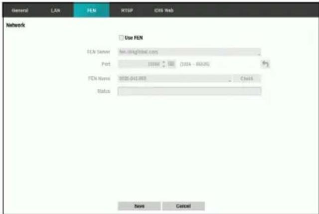
- Use FEN: Check if you wish to use FEN service.
- FEN Server: Enter the FEN server's IP address or domain name.

If you have configured the DNS Server setting under Network - IP Address, you can enter the FEN server's domain name instead of its IP address in the FEN Server field.
- Port: Specify the FEN server's port number.

If using an IP router (or NAT), port configuration and other network functions will depend on the usage method of the IP router (or NAT).
- FEN Name: After entering the DVR name you wish to register on the FEN server, check and register the entered name. This is a unique DVR name that will be registered on the FEN server.

- You will not be able to save FEN settings unless you click on the Check button next to the DVR Name field and check the entered name's availability.
- You will be prompted with an error message if you do not enter DVR name or enter a name already registered to the FEN Server.
- If the FEN name contains the #, \, and/or % symbol, it might not be able to connect to the DVR from the IDIS Web program.
- Status: Used to check the status of the device being registered to the FEN server.
Select Save after making changes to register the DVR's name to the FEN server.

If FEN has been configured correctly, the FEN server's help desk information will be displayed in the Help Desk field the next time you access the FEN Setup screen.
RTSP
RTSP service allows you to monitor real-time using the Real-Time Streaming Protocol.
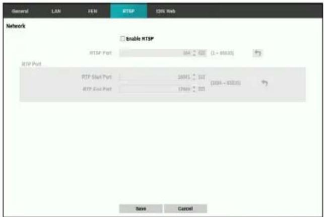
- RTSP Port: Set the port number of the RTSP server obtained from your system administrator.
- RTP Port: Set the start/end port number of the RTP server obtained from your system administrator.

- You can access a remote DVR and monitor live video images using media players, such as VLC Player, supporting RTSP service. Start the media player on your local PC and enter "rtsp://ID:Password@IP address:RTSP port number/trackID=channel number&streamID=stream number".
• Some media players might not play video properly depending on network conditions.
- RTSP service might not be supported, depending on the type of media player.
IDIS Web
IDIS Web service allows you to monitor and search video remotely without setting specific on-line programs.
![General LAN FEN MTSP IDIS Web Network Use IDIS Web Service Port 12006 [004 - 68334] Save Cancel](/content/2026/05/1065211/images/8a7373a549e545cbaf5ef6fe006320f9e14b4ea7804aaa84a668f6620e3c9b0c.jpg)
- Use IDIS Web Service: Enable/disable IDIS Web.
- Port: Set the port number used when accessing IDIS Web by using the Up and Down arrow buttons to increase or decrease the numbers.
Notification Setup
Callback
Configure Callback settings.
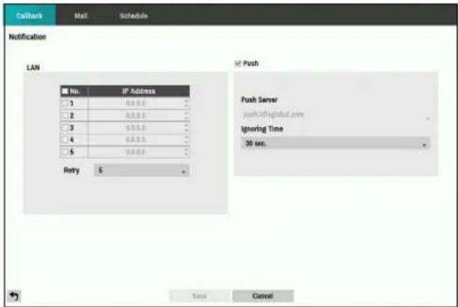
• LAN: Enter the IP address of the receiving server and set Retry to between 1 and 10 in case of connection failure.
- Push: Send out event-related messages to mobile phone.

Enable to receive the event occurred in DVR on the mobile phone(Android, iOS). The DVR must be registered and set in mobile phone.
Configure Mail settings.
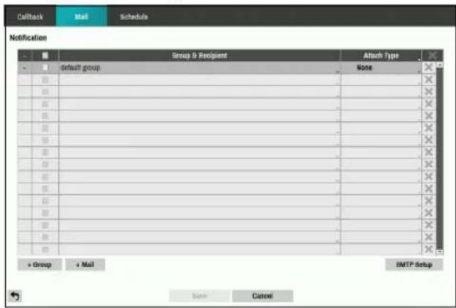
- +Group: Add a recipient group and select the image file format attached to an email.
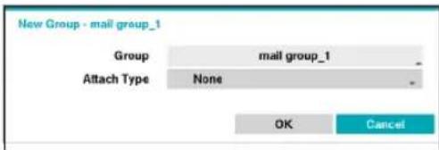
A virtual keyboard appears allowing you to enter the Group name. You can select among CBF, JPG, and MP4. When selecting CBF, the DVR will attach an event detected video clip to an email. When selecting MP4, the DVR will attach the event detected video clip (MP4 format) to an email.
• +Mail: Add a mail recipient.
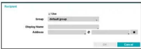
Assign the Recipient to a Group and enter the Recipient's Display Name. Enter the recipient's e-mail address and mail server provider. Select the ★ icon to select the mail server provider from a list of registered SMTP mail server providers.

The recipient's mail address must be in the correct email format and contain the @ symbol.
Select the Attach Type icon to attach event recordings to outgoing mails.
Select the ✗ icon to remove the account.
SMTP Setup
Select SMTP Setup at the bottom right corner of the screen to configure an SMTP server.
1 Enter the SMTP Server's IP address or domain name and then configure the Port and Sender settings.
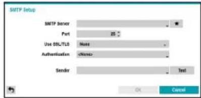
Default SMTP server port number is 25. Select Test to send out a test mail using the current settings. Select SSL/TLS or STARTTLS depending on the security connection which the server supports.

- If you have configured the DNS Server setting under Network - IP Address, you can enter the STMP server's domain name instead of its IP address in the SMTP Server field.
- Select the ★ icon to select the mail server provider from a list of registered SMTP mail server providers.
- Address entered under Sender must be in the correct email format and include the @ symbol.
If user authentication is required by the SMTP server, select Use and then enter the User and Password information.
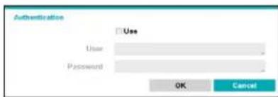
2 Select OK to apply and exit.

This product contains content developed by OpenSSL Project for use in Open SSL Toolkit (http://www.openssl.org/).
Schedule
Select the + icon at the lower left corner of the screen to add a notification schedule.
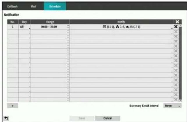
- Day: Add different schedules for different days of the week.
- Range: Change the event notification time frame.
- Notify: Select which notifications to generate when an event occurs. Select Mail, LAN 1 through 5, Push, and/or Alert Window.

- In order to use the Notification (Callback) feature, the DVR must be registered on the remote program.
- Select the ✗ icon to delete the existing schedule.
- Summary Email Interval: Transmit event summary emails to a remote destination at specified intervals.
Display Setup
Refer to the Menu Use on page 20 for basic information on using the Setup menus.
OSD
Show OSD (On Screen Display) information on the bottom of the screen.
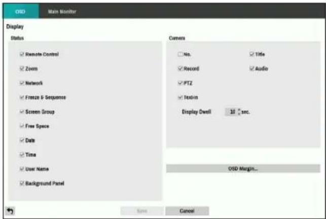
Status
- Remote Control: The icon 🔗 displays when the DVR can be controlled by the infrared remote control.
- Zoom: The icon 📄 displays on the enlarged video.
- Network: The icon 📋 displays when the unit is connected to a network via Ethernet. The icon 📋 displays on each camera when audio communication is available between the DVR and a PC running IDIS Center via Ethernet. The icon 📋 displays when VNC service is running.
- Freeze & Sequence: The icon ✿ displays while in the Freeze mode, and the □ displays while in the Sequence mode.
• Screen Group: Displays the number of screen group. - Free Space: The icon 📋 displays when the DVR is in the Recycle mode, and the percentage of available storage space displays when the DVR is not in the Recycle mode.
• Date and Time: Displays the date and time. - User Name: Displays the name of the current user logged in.
- Background Panel: Displays the background panel at the bottom of the screen in translucent black.
Camera
- No.: Displays the camera number on the upper left corner of the camera screen.
- Title: Displays the camera name on the upper left corner of the camera screen.
- Record: Displays recording and schedule icons.
- Audio: Displays the 🔊 icon on channels generating audio.
- PTZ: Displays the P icon on PTZ cameras.
- Text-In: Displays strings received from text-in devices. Select Display Dwell and specify how long to display the text-in string. Text-in strings are shown on the single screen only.
- OSD Margin: Displays how OSD text will be displayed on the monitor. You can adjust the horizontal and vertical margins so that text and icons will not be hidden beyond the edges of the monitor.
Main Monitor
Configure monitor-related settings.
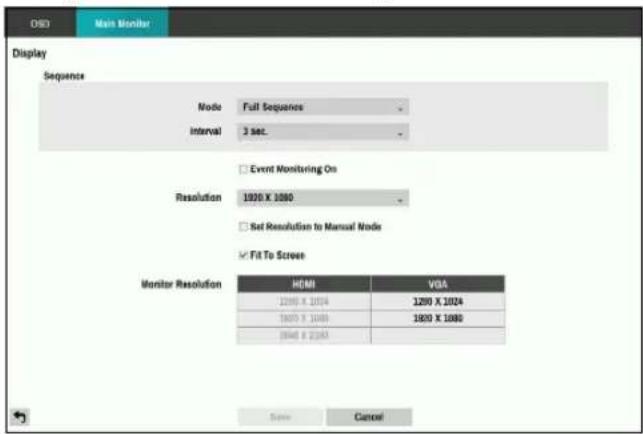
- Mode: Select between Full Sequence and Cameo Sequence. In the full sequence mode, the DVR sequences through the cameras and displays them full screen. In the cameo sequence mode, the bottom right window in a multi-screen format sequences through the cameras.
- Interval: Select between 1 secs and 1 mins. For more information on Sequence, refer to the Sequence on page 10.
- Event Monitoring On: With Event Monitoring enabled, video feed from the camera configured to start recording when an event occurs is shown on the screen. For more information on Event Monitoring, refer to the Event Monitoring on page 16.
- Resolution: Select 1280 x 1024, 1920 x 1080, 3840 x 2160.
- Set Resolution to Manual Mode: Set the resolution manually regardless of the resolution supported by the monitor.

- Supported resolutions may be restricted depending on the monitor.
• We recommend that you use 1920 x 1080 resolution.
- Monitor Resolution: Displays the resolution information of monitors currently connected to the DVR.
Searching Video
While in the search mode, pressing the MENU button displays the following Search menu on the right edge of the screen. Pressing the MENU button again hides the menu. You can navigate through menus and items by pressing the arrow buttons.
Search Menu
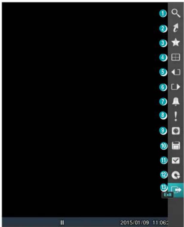
① Search
Search by changing Event Log Search, Record Table Search and Text-In Search.
② Go to
- Go to the First: Displays the first recorded image.
- Go to the Last: Displays the last recorded image.
- Go to the Date/Time: Displays the Go to the Date/Time screen.
③ Bookmarks
Add the current playback point to the bookmark list.

The maximum number of bookmarks that can be saved is 64.
④ Display
Used to change the screen layout to single screen, 2x2, 1x5, 1x7, 3x3.
- OSD On/Off: Enables/disables the OSD feature.
⑤ ⑥ Previous/Next Group
Loads the previous/next screen group.
⑦ Alarm
Pressing this button while the alarm has been activated resets all DVR alarm outputs, including the built-in buzzer.
⑧ Panic Record
Use the Panic Record feature.
⑨ Camera Menu
- Zoom: Zoom and choosing the camera number zooms the current playback image of the selected camera on the screen. Right-click on the mouse and drag to change the orientation, and use the wheel with the left-click on the mouse to zoom in/out more precisely.
- Audio: Audio toggles audio playback On and Off. Recorded audio will be played when the DVR displays a camera with recorded audio in full screen mode.
- Hide Text-In: Hide the text-in data on the screen if the video was recorded with text-in data.
- Edit Group: Enter to the Edit Group mode in the split screen layout.

The Camera Menu also can be displayed by clicking the right mouse button on the screen while in the search mode.
⑩ Export
- A-B Clip Copy: Designate a start point and an end point and copy the data in between.
- Clip Copy: Open up the Clip Copy Setup window for designating points A and B.
⑪ Status
- Allow you to check the status of the DVR's system, event status and storage.

Selecting Status will only be enabled for a user who has System Check authority.
⑫ Data Source
- Record: Search recording data contained in the main recording device.
- Other: Search data recorded while disks used in other systems were connected.
⑬ Exit
Exit the search mode and enter the live monitoring mode.
Context Menu
Right-click on the Camera screen to access the context menu.
- Zoom: Zoom in.
- Edit Group: Enter to the Edit Group mode in the split screen layout.
- Exit Search: Exit the search mode and enter the live monitoring mode.
Event Log Search
Select Event Log Search from the Search menu to bring up the Event Log Search Setup window.
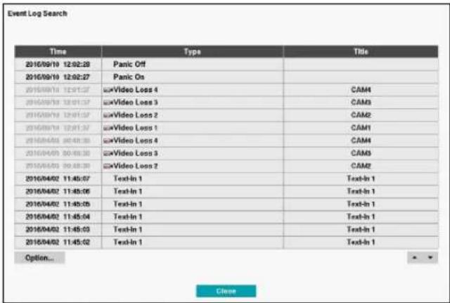
Select an event to display the recording made on the selected time and date (paused state). Select the Play button in the middle of the screen to start playing back the recording. Use the screen form to load recordings from other cameras.
You can also narrow your event search by selecting the Option... button and setting up the new search condition.
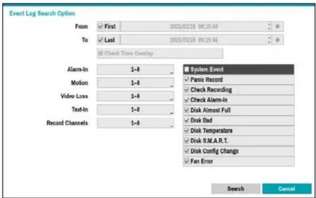
You can uncheck the First and Last options at the top of the Event Log Search window and specify the search time frame manually.

Select First for From and Last for To to select the entire recording from start to end.
If designating From or To settings manually, you will be able to enable/disable the Check Time Overlap option.

If the system's clock has been changed and the designated From or To point exists at more than one location, you will have to choose one. Only the events that took place between the selected From and To points will be searched. If Check Time Overlap has not been selected, events from the entire From and To range will be searched.
Camera Filter
- Alarm-In: Select which channels to search alarm-in events in.
- Motion: Select which channels to search motion detection events in.
• Video Loss: Select which channels to search video loss events in. - Text-In: Select which channels to search text-in events in.
- Record Channel: Select which record channels to search events in.

Selected record channels are searched for events with at least one linked recording. If no camera is selected, only the events with no linked recording camera are searched.
- Use event filters to include/exclude specific system events such as Panic Record, Check Recording, Check Alarm-In, Disk Almost Full, Disk Bad, Disk Temperature, Disk S.M.A.R.T., Disk Config Change, and Fan Error from the search.
Record Table Search
Select Record Table Search from the Search menu to bring up the Record Table Search Setup window.

① Record Table
Display the current channel's recording information.

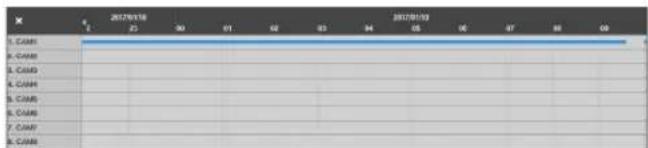
Recording date and time are shown on the top of the search window. The indicator line on Record Table indicates the current playback position. Use the arrow buttons on the remote control to move the current playback position in units of individual sectors. Alternatively, use the mouse to jump to the desired playback position.

• Farther back the data is on the record table, the more recent it is.
- If the system's clock is changed to a previous date and time, it is possible for multiple recordings with the identical time stamp to exist. Overlapped segments are highlighted in yellow.
Selecting or on the left-bottom of the search window changes the size of search window and displays Expanded view(the recording information of each camera channel), Standard view(combined recording information of all camera channels), and Compact view(only the toolbar).

Recording Data Bar Colors
| Blue Time Lapse Recording |
| Purple Event Recording |
| Yellow Pre-Event Recording |
| Red Panic Recording |
② Zoom
Select ⬕ (zoom-in) to compose recording data in 1-minute segments and select ⬇ (zoom-out) to compose recording data in 3-minute segments. Selecting zoom-out displays more time in one screen than zoom-in screen.
If recording from points in time prior or after the time frame displayed on the screen is available, scrolls appear on both ends of the date and time information line. Scroll using the arrow buttons on the remote control or by dragging with the mouse to check recording data.
③ Calendar Search
Use the calendar to search for video recordings by specific dates.
Dates containing video recordings are highlighted in black. Selecting a date containing video recording data loads the earliest recording from that date (paused state). Selected date is highlighted in light blue.
④ Search Menu
- Go to: Search video recordings based on date and time. Specify the date and time and then select Go to jump to the corresponding video recording.
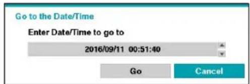
- Clip-Copy: Clip a video segment and saves it.
- Zoom: Zoom the current playback image.
- Slow Play: Search the playback screen at low speeds. Select the desired playback speed (x1/2, x1/3, x1/4, x1/6, x1/8) and then select Play.
⑤ Bookmark
Add the current playback point to the bookmark list.

The maximum number of bookmarks that can be saved is 64.
⑥ Playback Controls
Play and scan through video recordings. Playback controls have the same functions as their remote control counterparts.
| ◀| | Skips to the previous screen (while in paused state). |
| ▶/|| | Plays the video in normal speed and displays ▶ on the screen. Pressing the button during playback pauses the video and displays || on the screen. |
| |▶ | Skips to the next screen (while in paused state). |
| ◀◀ | Scans backward through the video at a fast rate: X16, X32, X64, X128, X256. (Press to cycle through ◀, ◀and thespeed) |
| ▶▶ | Scans forward through the video at a fast rate: X16, X32, X64, X128, X256. (Press to cycle through ▶, ▶and thespeed) |
Text-In Search
Select Text-In Search from the Search menu to bring up the Text-In Search window.
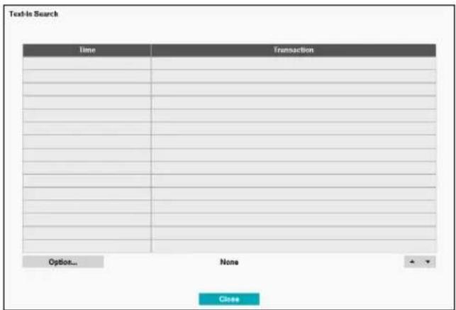
Select a Transaction to display the video recording that corresponds to the selected time and date (paused state).

Text-in information is superimposed on the screen at normal playback speed. The information is not shown under any other playback speed.
Select Option... to configure Text-In Search options.
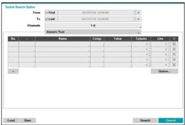
- Select First under From and Last under To to search the recording from start to finish. Alternatively, you can uncheck the First and Last options and specify the search time frame manually.

Selecting button, the bookmark list displays and the bookmark point you selected will be the starting date and time.
- Channels: Select a channel.
- Select Any Text-In Product to select a device type.
-
+: Add a search variable.
-
Option...: Select whether or not the search will find only text strings in which the case matches, find only exact words that match with the word you entered during text-in setup, or delete transactions duplicated within text input strings.
- Load: Retrieve stored search option settings.
- Save: Save the current search option settings.
Once all the options have been configured, select Search to begin the search and return to the Text-In Search setup window.
Bookmarks
Select Bookmarks from the Search menu to bring up the Bookmarks Setup window.
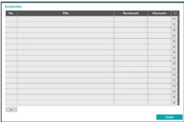
Select the + icon to add a bookmark to the current playback position. Use the virtual keyboard to enter the bookmark name and use the arrow buttons to highlight the bookmark point for which you would like to see video. The ✗ icon can be used to delete a Bookmark.

The maximum number of bookmarks that can be saved is 64.
Clip Copy
Clip Copy
Select Export – Clip Copy from the Search menu or press the remote control's BACK UP button for more 3 seconds while in Live or Playback mode to open up the Clip Copy setup window. Specify the From and To settings.
A-B Clip Copy
Designate a start point and an end point and copy the data in between. Select Clip-Copy – A-B Clip Copy from the Search menu to set point A. The ▶ icon will appear on the status indicator area on the upper right corner of the screen. Select Clip-Copy – A-B Clip Copy once again to set point B. The Clip Copy Setup window will appear. Select A and B points are automatically applied as From and To values.
![Clip-Copy Data Source Record From First 2017/01/19 09:59:16 To Last 2017/01/19 09:59:16 Channels 1-8 Password Dest. 1. SanDisk Ultra [15.00 GB] File name 20170119.exe Include Text-In Data Use Site Info Progress Start Close](/content/2026/05/1065211/images/e7eeb9994c957e87d67e862d18c0fd41492580a9efbe099075c9b5400b62d69a.jpg)
- Channels: Specify which channel to save the recording to.
- Password: Enable password protection for the saved video clip and assign a password.
- Dest.: Select which storage media to use.

- The DVR displays the volume as 30GB regardless of the actual disk volume and the maximum size limit on Clip Copy files is 30GB.
- If the video clip is uploaded after being clip-copying, video clips will be deleted.
- If there are same files, the video clips cannot be copied.
- File name: Designate a name for the file. The name may be up to 63 characters in length.

Special characters such as \, /, :, *, ?, !," <, >, and | are not permitted.
- Include Text-In Data: Enabling this option will save the video clip along with any available text-in data.
- Use Site Info: Add Site info to the Clip Copy file's name.

Special characters contained in the location info (such as \, /, :, ;, *, ?, !, ", <, >, and |) will be replaced with _ when the information is added to the file name.
Selecting Start displays a calculation on the size of the data to be copied. Check the calculation and then select Continue to proceed. While Clip Copy is in progress, you can select Cancel to cancel the process or select Close to allow the window to run in the background. Selecting Close does not cancel Clip Copy. Once the process is complete, you will be prompted with a confirmation window.

- Press the remote control's BACK UP button for more 3 seconds while in Live or Playback mode to open up the Clip Copy setup window with One-Touch mode.
-
One-Touch Clip Copy configures the storage range automatically based on the storage drive's capacity. If there is insufficient space available on the selected storage device, you will only be able to Clip Copy an amount of data equaling the remaining space available on the storage device.
-
Clip Copying a segment that is more than 2GB in size produces multiple files that are up to 2GB in size, each.
- Clip Copy files can be played back on Windows systems. For more information, refer to the IDIS Center operation manual.
- For USB flash memory devices, the DVR supports the FAT32 file format only.

Do not disconnect the USB cable or power off the USB device while USB Clip Copy is in progress. Doing so can cause the DVR to malfunction or critically damage the external USB device's file system. You may be prompted with an error message when trying to back up on the device. If so, you will need to restart the DVR. If the USB hard disk's file system has been damaged, restarting the DVR will not solve the problem and the aforementioned error message will continue to be displayed each time you attempt a backup. If this is the case, you will need to format the HDD or use a recovery program to repair the damage to the drive's file system.
Overlapped Recording Search
If the system's clock is changed to a point in the past, overlapping recordings may be produced. Overlapped recordings have to be searched in segments.
For example, making a recording from 1 o'clock to 5 o'clock, changing the system's clock at 5 o'clock to 3 o'clock, and then continuing to record until 6 o'clock produces two recordings that overlap between 3 o'clock and 5 o'clock. This results in two segments for the period between 3 and 5.
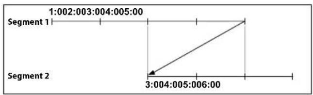
When searching overlapped video recordings, you can choose a specific point in time or a time frame. If you use the Go to the Date/Time option and select a point within the overlapped time period (4 o'clock, for example), you must specify 4 o'clock in which of the two existing segments.
Select a Segment
1: Segment 20
2: Segment 21
If you use the Event Log Search or Motion Detection option and select a time frame within the overlapped time period (4 o'clock to 5 o'clock, for example), you must choose between the two redundant sets of From and To values. Selectable search ranges are as follows:
• 4 o'clock in segment 1 to 5 o'clock in segment 1
• 4 o'clock in segment 1 to 5 o'clock in segment 2
• 4 o'clock in segment 2 to 5 o'clock in segment 2
Select a Range
1: Scope 1 \~ 3
2: Scope 1 \~ 2
3: Scope 2 \~ 2
IDIS Web is a program that allows you to view and search video from remote locations over the Internet and can be accessed on a regular web browser such as Internet Explorer.
System requirements for running IDIS Web are as follows:
- OS:Microsoft ^ Windows ^ 7 (Home Premium, Professional, Ultimate) or Microsoft ^ Windows ^ 8 (Pro, Enterprise)
• CPU: Intel Pentium IV 2.4GHz or above (Core 2 Duo E4600 recommended) - RAM: 1GB or more
• VGA: 128MB or more (1280x1024, 24bpp or above) - Internet Explorer: Ver. 7.0 or above (32-Bit)

• IDIS Web only works with Microsoft Internet Explorer and will NOT work with other browsers.
- IDIS Web does not work in Microsoft® Windows® 8 metro UI.
1 Launch Internet Explorer and then enter the following information in the address bar.
– http://IP Address:Port Number (DVR system's IP address and IDIS Web port number configured under Network > General (Default Value: 12088))
- http://fen.idisglobal.com/FEN Name (FEN Name: DVR name configured on the FEN server)
– http://web.idisglobal.com (will be prompted to enter DVR's IP address or FEN name registered to the FEN server upon login)

Contact your network administrator for the IP address of the DVR you wish to connect to and the IDIS Web port number.
2 When prompted with the IDIS Web login window, select LIVE-PORT or PLAY-PORT as the desired mode. Enter the ID and password and click LOGIN to sign in using the selected mode.
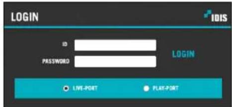
If connecting by entering http://web.idisglobal.com, enter the DVR's IP address in the Device Address field. Selecting the Use FEN Service option on the login window allows you to enter the DVR name registered to the FEN server instead of its IP address. You will be prompted to enter the FEN server's address and port number under Setup.

- Do not close the login window while IDIS Web is running. Switching over to Web Live or Web Search mode can cause a script error, requiring you to restart the IDIS Web program.
- If running IDIS Web, the bottom section of the screen may get cut off if the address bar or the status bar is shown. In this case, change Internet Options so that the address bar or the status bar is hidden. (Tools → Internet Options → Security → Custom level... → Allow websites to open windows without address or status bars (Enable))
- To use IDIS Web on Microsoft Windows Vista or above, launch Internet Explorer by right-clicking on the icon and selecting the Run as administrator option. Otherwise, certain IDIS Web functions might not be available.
- Launching a new version of IDIS Web for the first time can cause Internet Explorer to load information from the previous version. In this case, navigate to Tools → Internet Options → General, delete temporary Internet files, and then restart IDIS Web.
- On Microsoft Windows Vista or above, lowered image transmission rate can prevent the screen from being displayed or updated. In this case, we recommend that you disable the computer's auto tuning function. Open the command prompt as an administrator. (Start → Accessories → Command Prompt → Right-Click and then select Run as administrator) Type in "netsh int tcp set global autotuninglevel=disable" and then press Enter. Restart the computer to apply the change. To enable auto tuning again, launch the command prompt as an administrator and then type in "netsh int tcp set global autotuninglevel=normal". Restart the computer to apply the change.
Web Live Mode
A remote web monitoring program that allows you to monitor images from remote locales in real-time.
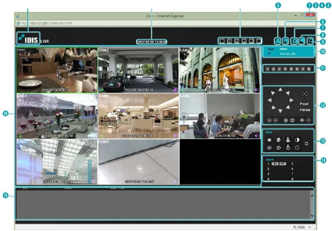
| 1 | Press ☑ to terminate WebGuard. | |
| 2 | Place the mouse pointer on the IDIS logo to check WebGuard's version. | |
| 3 | Displays the current time. | |
| 4 | Select the desired mode. Changing the mode places the selected camera in the first cell of the layout that will be changed. | |
| 5 | Click ☐ to print the current video screen using a printer connected to the computer. | |
| 6 | Click ☐ to save the current video screen as an image file. | |
| 7 | Click ☐ to configure rendering mode and OSD settings. Select rendering mode to adjust the video output rate or select which OSD elements to display on the screen from the OSD list. | |
| 8 | Click ☐ to switch over to setup menu. | |
| 9 | Click ☐ to switch over to Web Search mode. | |
| 10 | Shows login information. | |
| 11 | Select the camera you wish to monitor. Use the arrow buttons to navigate to the previous/next camera group. | |
| 12 | Used to control a PTZ camera at a remote location. | |
| 13 | Used to adjust live video quality. | |
| 14 | Controls remote alarm out devices. | |
| 15 | Event status window at the bottom of the screen displays a list of events detected at remote locales. | |
| 16 | Select a camera from the screen and right-click to bring up the pop-up menu.· Change Camera Title: Used to change the camera's name. Renaming the camera in Web Live mode does not affect the camera's name on the remote system. If no name is entered for the camera, the name used at the remote locale is shown on the screen. Renaming the camera in Web Live mode does not affect the camera's name on the remote system. If no name is entered for the camera, the name used at the remote locale is shown on the screen. | |
| Enable Audio: Enables audio transmission with remote locales. Select to display buttons. | ||
| Enables transmission of audio to the remote locale via microphone. | ||
| Enables playback of audio from the remote locale on speakers. | ||
| Enables two-way audio communication with the remote locale. | ||
| Disables audio transmission. | ||
| If the remote locale connected to supports audio transmission, icon appears on the corresponding camera screen. | ||
| Aspect Ratio: Changes the aspect ratio of the video displayed on the screen.- Fit to Screen: Fit the video to the size of the camera screen.- Fit to Aspect Ratio: Resizes camera screen to original aspect ratio of the video.- Half Size (x0.5) - 4 Times Bigger (x4): Displays the camera videos in the selected size based on the original size of the video. For example, original size (x1) displays the video in its original size. Half size (x0.5) through 4 times larger (x4) options are only available if there is enough space on the camera screen to accommodate the selected size.Multi Stream: Select a stream.Anti-Aliasing Screen: Removes stair step effect (blocks) that is caused when zooming a video to improve overall quality of video output. | ||
Web Search Mode
A remote web search program that allows you to search for recordings from remote locales in real-time.

While in Web Search mode, connection to remote locales will terminate automatically after 30 minutes of inactivity.
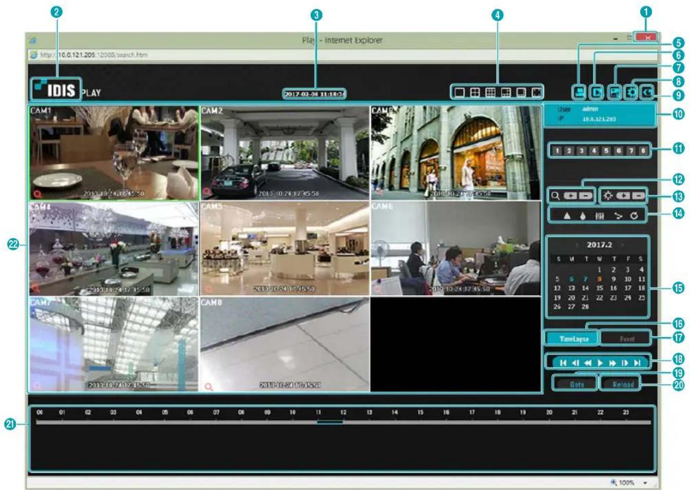
| 1 | Press x to terminate IDIS Web. | |||
| 2 | Place the mouse pointer on the IDIS logo to check IDIS Web's version. | |||
| 3 | Displays time information of the video recording from the remote DVR. | |||
| 4 | Select the desired mode. | |||
| 5 | Click to print the current video screen using a printer connected to the computer. | |||
| 6 | Click to save the video recording as an executable file. | |||
| 7 | Click to save the current video screen as an image file. | |||
| 8 | Click to configure rendering mode and OSD settings. Select rendering mode to adjust the video output rate or select which OSD elements to display on the screen from the OSD list. | |||
| 9 | Click to switch over to Web Live mode. | |||
| 10 | Shows login information. | |||
| 11 | Select the camera you wish to search. Use the arrow buttons to navigate to the previous/next camera group. | |||
| 12 | Zoom in or out on the video. | |||
| 13 | Adjust image brightness. | |||
| 14 | Apply image filters (Sharpen, Blur, Equalizer, Interpolation, and Revert) to the images. Image calibration is applied only during the paused state. Image calibration is applied only during the paused state. | |||
| 15 | Use the calendar to search for video recordings by specific dates.Dates containing video recordings are highlighted in light blue. Selecting a date containing video recording data loads the earliest recording from that date(paused state). Selected date is highlighted in orange. | |||
| 16 | Select TimeLapse to enable time lapse search mode and search/play back video recordings in chronological order. In Time Lapse Search mode, search is conducted by selecting days on the calendar. The time table at the bottom displays recording data information for the selected date. Select a point in time to display video from that moment. If multiple recordings are available for the selected point in time, you can select the desired segment. | |||
| 17 | Select Front to enable event search mode and search for events matching user-designated parameters. | |||
| 18 | Use the playback controls to play back video. | |||
| Go to First | Play by Frame (forwards) | |||
| Rewind | Fast Forward | |||
| Play by Frame (backwards) | Go to Last | |||
| Play/Pause | ||||
| 19 | Click Gato to designate recent recordings you wish to search and then jump to a specific point in the recording. | |||
| 20 | Click Reload to reload recent video recordings from remote locales. | |||
| 21 | Indicates the selected camera's recording data on a time bar. If the camera's system clock has been changed to a point in the past and more than one recording exists at the same point in time as a result, you will be able to choose which segment to search from the segment menu on the upper right portion of the time table. | |||
| 22 | Select a camera from the screen and right-click to bring up the pop-up menu.· Change Camera Title: Used to change the camera's name. Renaming the camera in Web Search mode does not affect the camera's name on the remote system. If no name is entered for the camera, the name used at the remote locale is shown on the screen. Renaming the camera in Web Search mode does not affect the camera's name on the remote system. If no name is entered for the camera, the name used at the remote locale is shown on the screen. | 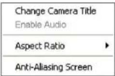 |
| · Enable Audio: If audio was recorded with the video, enabling this option plays audio upon playback (limited to single-screen playback).· Aspect Ratio: Changes the aspect ratio of the video displayed on the screen.· Anti-Aliasing Screen: Removes stair step effect (blocks) that is caused when zooming a video to improve overall quality of video output. | ||
Index
A
Alarm-In 37
Alarm-Out 41
Audio Recording 19
E
Event Monitoring 16
L
LAN 43
M
Motion Search 52, 53
Mouse 21
0
OSD 48
P
Panic Recording 18
Pre-Event 35
R
Recording 18
s
Search 50
Storage 30
T
Text-In 38
Text-In Search 54
V
Video-Analytics 35
IDIS®
IDIS Co., Ltd.
For more information, please visit at
www.idisglobal.com
- Digital Video Recorder
- Safety Precautions
- CAUTION
- Important Safeguards
- Read Instructions
- Retain Instructions
- Cleaning
- Attachments
- Water and/or Moisture
- Ventilation
- Accessories
- Power Sources
- Power Cords
- Lightning
- Overloading
- Objects and Liquids
- Servicing
- Damage requiring Service
- Replacement Parts
- Safety Check
- Field Installation
- Correct Batteries
- Tmra
- Elevated Operating Ambient Temperature
- Reduced Air Flow
- Mechanical Loading
- Circuit Overloading
- Reliable Earthing (Grounding)
- In-Text
- Symbol Type Description
- User's Caution Statement
- FCC Compliance Statement
- WEEE (Waste Electrical & Electronic Equipment)
- Correct Disposal of This Product
- Copyright
- Registered Trademarks
- 1
- Part 1 - Getting Started ....9
- 2
- Part 2 - Configuration....20
- Event Setup 35
- Camera Setup 39
- Device Setup....41
- Network Setup 42
- Notification Setup....46
- Display Setup 48
- Part 3 - Search....50
- Searching Video....50
- Overlapped Recording Search ....57
- 5
- Part 4 - IDIS Web....58
- Part 5 - Appendix....65
- Login
- Live Mode
- Live Menu
- - Login/Logout
- - Display
- - Previous/Next Group
- - Freeze
- - Alarm
- - Panic Recording
- - Sequence
- Full Sequence
- e.g.) Full Sequence in single screen mode
- Cameo Sequence
- - Camera Menu
- - Search
- - Setup
- - Status
- Video Display Area
- Camera Screen
- Camera Menu
- Edit Group
- Zoom
- PTZ Control
- Setting Up a PTZ Preset
- Event Monitoring
- Covert Camera
- Status
- Event Status
- Storage
- Context Menu Access
- Video Recording
- Panic Recording
- Audio Recording
- Video Recording Playback
- Remote Control Buttons during Playback
- Context Menu
- All Channel Playback
- Menu Use
- Text Input via Virtual Keyboard
- Batch Assignment
- Mouse
- System Setup
- General
- Part 2 - Configuration
- Quick Wizard
- Choose the desired Recording Method and click Next.
- Choose the desired Recording Quality and click Next.
- Click Finish to exit Quick Wizard.
- Network Wizard
- Select Network Wizard.
- Specify whether the system is connected to the Internet and click Next.
- Select Network Configuration and then click Next. Select either Auto Configuration or Manual Configuration and then click Test to test the system's current network configuration.
- Date/Time
- Select Automatic Sync.
- Specify the server synchronization Interval.
- Select OK to apply and exit.
- User
- System Event
- About
- Record Setup
- Schedule
- Simple Mode Options
- Advanced Mode Options
- Pre-Event
- Event Setup
- Motion
- Alarm-In
- Video Loss
- Text-In
- Camera Setup
- PTZ
- Privacy Masking
- Device Setup
- Audio
- Alarm-Out
- Network Setup
- LAN
- DHCP
- FEN
- RTSP
- IDIS Web
- Notification Setup
- Callback
- SMTP Setup
- Display Setup
- OSD
- Camera
- Main Monitor
- Searching Video
- ① Search
- ② Go to
- ③ Bookmarks
- ④ Display
- ⑤ ⑥ Previous/Next Group
- ⑦ Alarm
- ⑧ Panic Record
- ⑨ Camera Menu
- ⑩ Export
- ⑪ Status
- ⑫ Data Source
- ⑬ Exit
- Event Log Search
- Camera Filter
- Record Table Search
- ① Record Table
- ② Zoom
- ③ Calendar Search
- ④ Search Menu
- ⑤ Bookmark
- ⑥ Playback Controls
- Text-In Search
- Bookmarks
- Clip Copy
- A-B Clip Copy
- Overlapped Recording Search
- Select a Segment
- Select a Range
- Web Live Mode
- Web Search Mode
- Index
- A
- E
- L
- M
- 0
- P
- R
- s
- T
- V
- IDIS®
Brand : IDIS
Model : TR-2508
Category : Video recorder