VS-211XS - Network switch Kramer - Free user manual and instructions
Find the device manual for free VS-211XS Kramer in PDF.


| Product Type | 2x1 4K Auto Switcher for HDMI signals |
| Model | VS-211XS |
| Brand | Kramer |
| Dimensions (W x D x H) | 19 cm x 6 cm x 2.7 cm (7.5" x 2.4" x 1.1") |
| Net Weight | 0.32 kg (0.7 lbs) |
| Shipping Weight | 0.79 kg (1.7 lbs) |
| Power Supply | 5V DC, 810 mA (adapter included) |
| Power Consumption | 4W (810 mA @ 5V) |
| Video Inputs | 2 x HDMI (female) |
| Video Output | 1 x HDMI (female) |
| Audio Output | 1 x Balanced stereo line level (5-pin terminal block) |
| Control Interfaces | RS-232 (3-pin terminal block), Ethernet (RJ-45), Remote contact closure (8-pin terminal block), Front panel buttons and DIP-switches |
| Max Video Resolution | 4K@60Hz (4:4:4), 17.82 Gbps data rate |
| HDCP Compliance | HDCP 2.2 |
| Auto-Switching Modes | Last connected or Priority |
| Built-in Maestro Control | Room automation and triggers |
| CEC Gateway | IP-driven CEC routing via built-in gateway |
| EDID Management | Copy from input/output, default, or custom file |
| Firmware Upgrade | Via Ethernet (web pages) or RS-232 (K-Upload) |
| Enclosure Type | DemiTOOLS, aluminum fan-less design |
| Operating Temperature | 0° to 40°C (32° to 104°F) |
| Storage Temperature | -40° to 70°C (-40° to 158°F) |
| Humidity | 10% to 90% RHL non-condensing |
| Safety Compliance | CE, UL |
| Environmental Compliance | RoHS, WEEE |
| Accessories Included | Power adapter and cord |
| Mounting | Tabletop with included rubber feet or bracket; optional rack adapter |
Frequently Asked Questions - VS-211XS Kramer
User questions about VS-211XS Kramer
0 question about this device. Answer the ones you know or ask your own.
Ask a new question about this device
Download the instructions for your Network switch in PDF format for free! Find your manual VS-211XS - Kramer and take your electronic device back in hand. On this page are published all the documents necessary for the use of your device. VS-211XS by Kramer.
USER MANUAL VS-211XS Kramer
Typical Applications 4
Defining VS-211XS and VS-411XS 5
VS-211XS / VS-411XS Front Panel 5
VS-211XS / VS-411XS Rear Panel 6
Mounting VS-211XS / VS-411XS 7
Connecting VS-411XS 8
Connecting Output to a Balanced/Unbalanced Stereo Audio Acceptor 9
Connecting to VS-411XS via RS-232 9
Principles of Operation 10
Input Auto-Switching 10
IP-Driven CEC Signals Routing via Built-in Control Gateway 11
Maestro Built-in Control and Automation Configuration 12
Maestro Kramer Aware Touch Panel Control 14
Operating and Controlling VS-411XS 15
Using Front Panel Buttons 15
Setting DIP-Switches 15
Using Contact Closure Remote Control Pins 16
Acquiring and Discovering Plug-and-Play IP Address 17
Operating via Ethernet 18
Using Embedded Web Pages 22
Selecting an Input 23
Adjusting Audio Output Volume 24
Viewing and Adjusting General Settings 24
Setting Remote Buttons 25
Loading and Saving Settings 25
Resetting Device 26
Defining IP Settings 27
Define CEC Gateway Settings 29
Setting Time and Date 30
Upgrading the Firmware 31
Setting Security 32
Setting Auto Switching Priorities 34
Setting Input Color Depth 34
Setting Output Audio Source for De-embedded Audio 35
Setting HDCP Support 35
Setting Video Signal Timeouts 37
Managing EDID 38
Configuring Device Control and Automation 41
Operating via Maestro Kramer Aware Touch Panel 45
Viewing About Page 59
Firmware Upgrade 60
Technical Specifications 61
Default Communication Parameters 62
Default Automation settings 62
Default EDID 66
Protocol 3000 69
Understanding Protocol 3000 69
Protocol 3000 Commands 70
Result and Error Codes 81
Introduction
Welcome to Kramer Electronics! Since 1981, Kramer Electronics has been providing a world of unique, creative, and affordable solutions to the vast range of problems that confront the video, audio, presentation, and broadcasting professional on a daily basis. In recent years, we have redesigned and upgraded most of our line, making the best even better!

This user manual describes VS-211XS and VS-411XS. These devices are identical except for the number of their inputs. Note that whenever VS-411XS is used in the user manual, it also refers to VS-211XS, unless specified otherwise. (A device is named specifically only when a device-specific feature is described).
Getting Started
We recommend that you:
- Unpack the equipment carefully and save the original box and packaging materials for possible future shipment.
- Review the contents of this user manual.

Go to www.kramerav.com/downloads/VS-211XS or www.kramerav.com/downloads/VS-211XS to check for up-to-date user manuals, application programs, and to check if firmware upgrades are available (where appropriate).
Achieving Best Performance
- Use only good quality connection cables (we recommend Kramer high-performance, high-resolution cables) to avoid interference, deterioration in signal quality due to poor matching, and elevated noise levels (often associated with low quality cables).
- Do not secure the cables in tight bundles or roll the slack into tight coils.
- Avoid interference from neighboring electrical appliances that may adversely influence signal quality.
- Position your Kramer VS-411XS away from moisture, excessive sunlight and dust.
Safety Instructions

Caution:
- This equipment is to be used only inside a building. It may only be connected to other equipment that is installed inside a building.
- For products with relay terminals and GPIO ports, please refer to the permitted rating for an external connection, located next to the terminal or in the User Manual.
• There are no operator serviceable parts inside the unit.

Warning:
- Use only the power cord that is supplied with the unit.
- To ensure continuous risk protection, replace fuses only according to the rating specified on the product label which is located on the bottom of the unit.
Recycling Kramer Products
The Waste Electrical and Electronic Equipment (WEEE) Directive 2002/96/EC aims to reduce the amount of WEEE sent for disposal to landfill or incineration by requiring it to be collected and recycled. To comply with the WEEE Directive, Kramer Electronics has made arrangements with the European Advanced Recycling Network (EARN) and will cover any costs of treatment, recycling and recovery of waste Kramer Electronics branded equipment on arrival at the EARN facility. For details of Kramer's recycling arrangements in your particular country go to our recycling pages at www.kramerav.com/support/recycling.
Overview
VS-211XS and VS-411XS are intelligent (2x1 and 4x1, respectively) automatic switchers for 4K HDR, HDMI™ video signals. VS-411XS offers an intelligent switching experience with built-in Maestro room control and the standard priority / last-connected switching function based on active video signal detection.
VS-411XS provides exceptional quality, advanced and user-friendly operation, and flexible control.
Exceptional Quality
- Plug & Play Auto Switcher – Automatically plays the switched source signal on the connected display according to user-configured preferences, such as priority or last-connected input. When the user manually switches, by pressing a button, the auto switching is overridden.
- I-EDIDPro™ Kramer Intelligent EDID Processing™ – Intelligent EDID handling, processing, locking and pass-through algorithm ensures plug & play operation for HDMI source and display systems.
- HDMI Signal Switching – HDCP 2.2 compliant, Supporting deep color, x.v.Color™, CEC, lip sync, HDMI uncompressed audio channels, Dolby TrueHD, DTS-HD, 2K, 4K, and 3D as specified in HDMI 2.0.
- Multi-channel Audio Switching – Up to 32 channels of digital stereo uncompressed signals for supporting studio-grade surround sound.
Advanced and User-friendly Operation
- Simple and Powerful Maestro Room Control – Out-of-the-box configured room control for a typical meeting room setup, and intuitive user interface enables you to fully control your meeting room elements. Room devices are controlled right out-of-the-box by an extensive range of triggers, including input/output connectivity, routing, and button pressing. By minimizing user intervention, Maestro room control saves meeting prep time and minimizes human error before presentations.
- Easy Remote Device Control – Control meeting and presentation devices connected to VS-411XS from the user-friendly Kramer Aware app on a compatible Kramer touch panel (sold separately). Kramer Aware includes a built-in, basic user-interface panel, pre-configured for Maestro-controlled typical meeting room setup.
- Simple Manual Switching Operation – Local panel buttons, or remotely connected contact-closure buttons, and optional Maestro Kramer Aware touch panel buttons, for flexible user input selection and switching control.
- Audio De-embedding – The digital audio signal passing-through to the HDMI output, is de-embedded, converted to an analog signal and sent to the stereo balanced analog audio output. This enables playing the audio on a locally connected professional audio system (such as DSP) and speakers, in parallel to playing it on the speakers connected to the AV acceptor device (such as TVs with speakers).
- Automatic Display Operation – Part of the out-of-the-box Maestro configured room automation. Meeting presentation is simplified by automatically turning ON/OFF a CEC-enabled display when the presentation source is plugged in / unplugged with user-defined shut-down delay.
- Easy Audio Control – Adjust the audio output volume or mute via front panel buttons, built-in Maestro and Kramer Aware touch panel buttons, embedded web pages control buttons, and remote IP or local RS-232 serial commands.
- IP-Based Firmware Upgrade – Ethernet-based, via a user-friendly software upgrade tool or via embedded web pages, enabling upgrade via Kramer Network management.
- Cost-effective Maintenance – Status LED indicators for HDMI ports facilitate easy local maintenance and troubleshooting. Remote IP-driven device management, and optional whole site management system, via built in web pages and RS-232 connection. Local and remote firmware upgrade via RS-232 or Ethernet connection tool ensure lasting, field proven deployment.
- Easy Installation – Compact DemiTOOLS® fan-less enclosure for user-reachable table mounting, or side-by-side mounting of 2 units in a 1U rack space with the recommended rack adapter.
Flexible Connectivity
- Comprehensive Unit Control and Configuration Options – Local control via DIP-switches, volume and mute buttons, and volume and mute contact closure switches. Distance control via user-friendly embedded web pages via the Ethernet, Protocol 3000 API commands via RS-232 serial communication transmitted by a PC, touch screen system or other serial controller.
Typical Applications
VS-411XS is ideal for the following typical applications:
- Corporate or educational AV meeting solution, where an intelligent, high-quality auto switcher is needed.
- Smart controllable switching in small to medium size meeting and training rooms.
Controlling your VS-411XS
Control your VS-411XS directly via the front panel push buttons, or:
- Via the Ethernet using built-in user-friendly web pages.
• Via optional Kramer Aware touch panel. - By RS-232 serial commands transmitted by a touch screen system, PC, or other serial controller.
• Via REMOTE dry contact pins.
Defining VS-211XS and VS-411XS
This section defines VS-211XS and VS-411XS front and rear panels.
VS-211XS / VS-411XS Front Panel
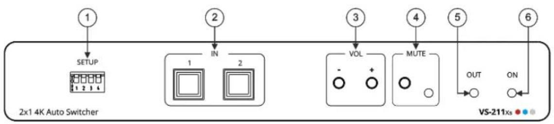
flowchart
graph TD
    A["1"] --> B["2x1 4K Auto Switcher"]
    C["IN"] --> D["1"]
    C --> E["2"]
    F["3"] --> G["VOL"]
    H["4"] --> I["MUTE"]
    J["5"] --> K["OUT"]
    L["6"] --> M["ON"]
    N["VS-211xs"] --> O["●"]
    P["○"] --> Q["○"]
Figure 1: VS-211XS 2x1 4K Auto Switcher Front Panel
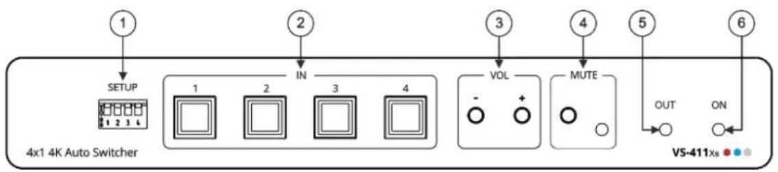
flowchart
graph TD
    A["1"] --> B["SETUP"]
    B --> C["1"]
    B --> D["2"]
    B --> E["3"]
    B --> F["4"]
    C --> G["VOL"]
    D --> H["+"]
    E --> I["MUTE"]
    F --> J["OUT"]
    F --> K["ON"]
    L["2"] --> M["IN"]
    N["3"] --> O["OUT"]
    P["4"] --> Q["OUT"]
    R["5"] --> S["OUT"]
    T["6"] --> U["OUT"]
    V["VS-411xs"] --> W["●"]
Figure 2: VS-411XS 4x1 4K Auto Switcher Front Panel
| # | Feature | Function | |
| 1 | SETUP 4-wayDIP-Switches | Set the operation DIP-switches (seeSetting DIP-Switcheson page15). | |
| 2 | IN Buttons | Press to select an HDMI input (button lights orange):VS-211XS: IN 1 and IN 2.VS-411XS: IN 1 to IN 4. | |
| 3 | VOL PushButtons | - | Press to decrease audio output volume. |
| + | Press to increase audio output volume. | ||
| 4 | MUTE | Push Button | Press to mute the audio output.The audio signal remains mute when using the VOL – button and unmutes automatically when pressing the VOL + button. |
| LED | Lights red when audio output is muted. | ||
| 5 | OUT LED | Lights green when an HDMI output is connected. | |
| 6 | ON LED | Lights green when the device receives power. | |
VS-211XS / VS-411XS Rear Panel
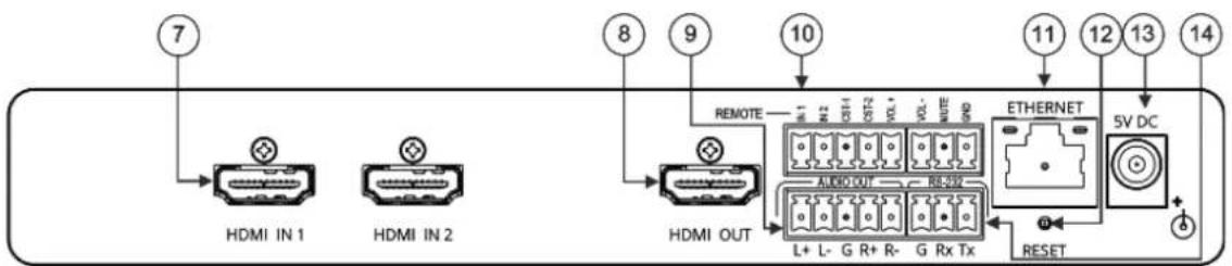
Figure 3: VS-211XS 2x1 4K Auto Switcher Rear Panel
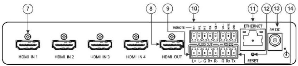
flowchart
graph LR
    A["HDMI IN 1"] --> B["⊕"]
    C["HDMI IN 2"] --> D["⊕"]
    E["HDMI IN 3"] --> F["⊕"]
    G["HDMI IN 4"] --> H["⊕"]
    I["HDMI OUT"] --> J["⊕"]
    K["REMOTE"] --> L["5V DC"]
    M["L+ L- G R+ R- G Rx Tx"] --> N["EITHERNET"]
    O["RESET"] --> P["5V DC"]
    Q["7"] --> R["⊕"]
    S["8"] --> T["⊕"]
    U["9"] --> V["⊕"]
    W["10"] --> X["⊕"]
    Y["11"] --> Z["⊕"]
    AA["12"] --> AB["⊕"]
    AC["13"] --> AD["⊕"]
    AE["14"] --> AF["⊕"]
Figure 4: VS-411XS 4x1 4K Auto Switcher Rear Panel
| # | Feature | Function |
| 7 | HDMI IN Connectors | Connect to an HDMI source:VS-211XS: HDMI IN 1 and HDMI IN 2.VS-411XS: HDMI IN 1 to HDMI IN 4. |
| 8 | HDMI OUT Connector | Connect to an HDMI acceptor. |
| 9 | AUDIO OUT 5-pin Terminal Block Connector | Connect to a balanced stereo audio acceptor. |
| 10 | REMOTE Terminal block Connector: | Connect to contact closure switches by momentary contact between the desired pin and common GND pin (seeUsing Contact Closure Remote Control Pins on page 16). |
| For VS-211XS:IN 1, IN 2/ CST-1, CST-2 | Select input 1 or input 2 (IN 1 or IN 2), or alternatively activate custom triggers (including CST-1 and CST-2 to GND) set up in Maestro.(Configured via the embedded web pages). | |
| For VS-411XS:IN 1, IN 2, IN 3, IN 4 | Select input 1 to input 4 (IN 1 to IN 4), or alternatively activate custom triggers set up in Maestro. (Configured via the embedded web pages). | |
| VOL+, VOL -, MUTE | Set the volume up or down (VOL+/-) and mute the audio output (MUTE). | |
| 11 | ETHERNET RJ-45 Connector | Connect to a PC via a LAN to control the device. |
| 12 | RESET Recessed Button | Press briefly to restart the device.Press and hold (5 seconds) to fully reset the device parameters to their default values,includingETH parameters. |
| 13 | 5V DC Power Connector | Connect to the power supply and to the mains electricity. |
| 14 | RS-232 3-pin Terminal Block Connector | Connect to a PC or a remote controller to control the device. |
Mounting VS-211XS / VS-411XS
This section provides instructions for mounting VS-211XS. Before installing, verify that the environment is within the recommended range:

- Operation temperature – 0° to 40°C (32 to 104°F).
- Storage temperature -40^ to +70^ (-40 to +158^ ).
- Humidity – 10% to 90%, RHL non-condensing.

Caution:
- Mount VS-211XS / VS-411XS before connecting any cables or power.

Warning:
- Ensure that the environment (e.g., maximum ambient temperature & air flow) is compatible for the device.
- Avoid uneven mechanical loading.
- Appropriate consideration of equipment nameplate ratings should be used for avoiding overloading of the circuits.
- Reliable earthing of rack-mounted equipment should be maintained.
• Maximum mounting height for the device is 2 meters.
Mount VS-211XS / VS-411XS in a rack:
- Use the recommended rack adapter (see www.kramerav.com/product/VS-211XS / www.kramerav.com/product/VS-411XS).
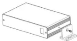
Mount VS-211XS / VS-411XS on a surface using one of the following methods:
- Attach the rubber feet and place the unit on a flat surface.
- Fasten a bracket (included) on each side of the unit and attach it to a flat surface. For more information go to www.kramerav.com/downloads/VS-211XS / www.kramerav.com/downloads/VS-411XS.
Connecting VS-411XS

Since the main difference between VS-211XS and VS-411XS are the number of inputs, from this section on, any description of VS-411XS applies also to VS-211XS, unless stated otherwise.

Always switch off the power to each device before connecting it to your VS-411XS. After connecting your VS-411XS, connect its power and then switch on the power to each device.
flowchart
graph TD
    A["Work Station"] --> B["HDMI"]
    B --> C["Set Top Box"]
    C --> D["DIP-31 Auto Switcher"]
    D --> E["HDMI"]
    E --> F["Display"]
    F --> G["Audio"]
    G --> H["Active Speakers"]
    H --> I["Laptop"]
    I --> J["ETHERNET"]
    J --> K["5V DC"]
    L["Configurable Buttons"] --> M["Dry Contact"]
    N["HDMI IN 1"] --> O["HDMI IN 2"]
    P["HDMI IN 3"] --> Q["HDMI IN 4"]
    R["HDMI OUT"] --> S["HDMI"]
    T["RS-232"] --> U["Laptop"]
    V["Eth"] --> W["Control System"]
    X["HDMI"] --> Y["HDMI"]
    Z["HDMI"] --> AA["HDMI"]
    AB["HDMI"] --> AC["HDMI"]
    AD["HDMI"] --> AE["HDMI"]
    AF["HDMI"] --> AG["HDMI"]
    AH["HDMI"] --> AI["HDMI"]
    AJ["HDMI"] --> AK["HDMI"]
    AL["HDMI"] --> AM["HDMI"]
    AN["HDMI"] --> AO["HDMI"]
    AP["HDMI"] --> AQ["HDMI"]
    AR["HDMI"] --> AS["HDMI"]
    AT["HDMI"] --> AU["HDMI"]
    AV["HDMI"] --> AW["HDMI"]
    AX["HDMI"] --> AY["HDMI"]
    AZ["HDMI"] --> BA["HDMI"]
    BB["HDMI"] --> BC["HDMI"]
    BD["HDMI"] --> BE["HDMI"]
    BF["HDMI"] --> BG["HDMI"]
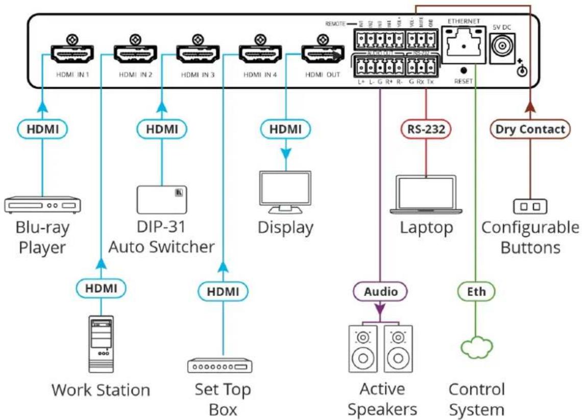
Figure 5: Connecting to the VS-411XS Rear Panel
To connect VS-411XS as illustrated in the example in Figure 5:
- Connect an HDMI source to the HDMI IN connectors 7, for example, Connect:
■ A Blu-ray player to HDMI IN 1.
■ A work Station to HDMI IN 2.
■ Kramer DIP-31 Auto Switcher to HDMI IN 3.
■ A Set top box to HDMI IN 4.
-
Connect HDMI OUT to an HDMI acceptor (for example, a display).
-
Connect AUDIO OUT to a balanced stereo audio acceptor (for example, Kramer Tavor 5-O active speakers).
-
Connect REMOTE dry-contact terminal block connectors ^10 to configurable buttons to select an input (see Using Contact Closure Remote Control Pins on page 16) or activate a custom Maestro trigger (see Configuring Device Control and Automation on page 41).
-
Connect the RS-232 3-pin terminal block connector ^140 to the RS-232 port on a controller (for example, a laptop) to control the VS-411XS.
-
Connect the ETHERNET RJ-45 port 1 to the LAN.
-
Connect the 5V power adapter to VS-411XS and to the mains electricity (not shown in Figure 5).
Connecting Output to a Balanced/Unbalanced Stereo Audio Acceptor
The following are the pinouts for connecting the output to a balanced or unbalanced stereo audio acceptor:
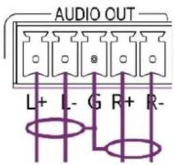
Figure 6: Connecting to a Balanced Stereo Audio Acceptor
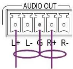
Figure 7: Connecting to an Unbalanced Stereo Audio Acceptor
Connecting to VS-411XS via RS-232
You can connect to VS-411XS via an RS-232 connection ⑭ using, for example, a PC.
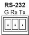
VS-411XS features an RS-232 3-pin terminal block connector allowing the RS-232 to control VS-411XS.
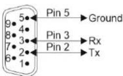
Connect the RS-232 terminal block on the rear panel of VS-411XS to a PC/controller, as follows:
From the RS-232 9-pin D-sub serial port connect:
- Pin 2 to the TX pin on the VS-411XS RS-232 terminal block.
- Pin 3 to the RX pin on the VS-411XS RS-232 terminal block.
• Pin 5 to the G pin on the VS-411XS RS-232 terminal block.
RS-232 Device
VS-411XS
Principles of Operation
This section describes the VS-411XS powerful operation principles:
• Input Auto-Switching on page 10.
• IP-Driven CEC Signals Routing via Built-in Control Gateway on page 11.
• Maestro Built-in Control and Automation Configuration on page 12.
• Maestro Kramer Aware Touch Panel Control on page 14.
Input Auto-Switching
Input selection is set by the DIP-switches (see Setting DIP-Switches on page 15) to either of the following modes:
- Manual
- Auto – Last connected
- Auto – Priority
By-default switching is set to Auto Last connected.

When in manual mode, a manual switch to an unconnected input stays connected to output. Manual switching overrides auto-switch mode.
In manual mode, select an input by:
- Pressing input front panel buttons.
- Using remote input selection switches (see Using Contact Closure Remote Control Pins on page 16).
- Sending RS-232 serial commands control (see Protocol 3000 Commands on page 70).
• Using the embedded web pages (see Selecting an Input on page 23). - Using Maestro Control on Kramer Aware touch panel (see Operating via Maestro Kramer Aware Touch Panel on page 45).
In auto-switching mode, switching selection is performed based on either last connected or priority input:
- In last connected mode, if the signal on the current input is lost, VS-411XS automatically selects the last connected input, (the delay depends on a configurable timeout).
- In priority mode, when the input sync signal is lost for any reason, the input with a live signal and next in priority is selected automatically, (the delay depending on the configurable signal-lost timeout, (see Setting Auto Switching Priorities on page 34).
IP-Driven CEC Signals Routing via Built-in Control Gateway
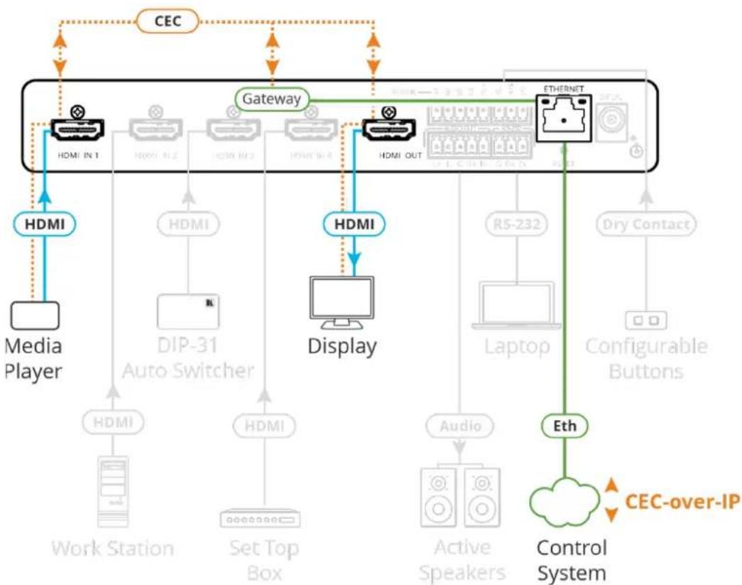
VS-411XS sends CEC commands from a control system, connected by LAN, via the VS-411XS built-in control gateway, to control devices that are connected to the VS-411XS HDMI output and the selected input.
The built-in control gateway sends the control commands to the connected controlled devices, and sends their received responses to the control system when DIP-switch 3 is enabled (see Setting DIP-Switches on page 15).
Figure 8 shows the VS-411XS built-in control gateway connection. A control system supporting CEC-over-IP (such as Kramer Control) is connected to the Ethernet port via LAN. The control system sends CEC commands to the selected input (IN 1, in this example) and the output, and receives responses from them.
flowchart
graph TD
    A["Media Player"] -->|HDMI| B["Desktop Computer"]
    B -->|DIP-31 Auto Switcher| C["Display"]
    C -->|HDMI| D["Internet"]
    D -->|Ethernet| E["Control System"]
    E -->|Eth| F["User Interface"]
    F -->|CEC-over-IP| G["Gateway"]
    G -->|HDMI IN 1| H["Internet"]
    G -->|HDMI OUT| I["Internet"]
    H --> J["Work Station"]
    I --> K["Laptop"]
    I --> L["Configurable Buttons"]
    I --> M["Dry Contact"]
    I --> N["Audio"]
    I --> O["Active Speakers"]
    I --> P["Set Top Box"]
    I --> Q["HDMI"]
    I --> R["HDMI"]
    I --> S["HDMI"]
    I --> T["HDMI"]
    I --> U["HDMI"]
    I --> V["HDMI"]
    I --> W["HDMI"]
    I --> X["HDMI"]
    I --> Y["HDMI"]
    I --> Z["HDMI"]
    I --> AA["HDMI"]
    I --> AB["HDMI"]
    I --> AC["HDMI"]
    I --> AD["HDMI"]
    I --> AE["HDMI"]
    I --> AF["HDMI"]
    I --> AG["HDMI"]
Figure 8: CEC Signals via Control Gateway
Built-in CEC gateway ON/OFF configuration and management (such as the CEC members logical addresses view) is performed via web-UI (see Define CEC Gateway Settings on page 29) and DIP-switches (see Setting DIP-Switches on page 15) for CEC notification settings.
Maestro Built-in Control and Automation Configuration
The VS-411XS built-in Maestro control and automation enables configuring triggers to simply create a sequence of actions that are carried out following trigger activation (see Configuring Device Control and Automation on page 41).
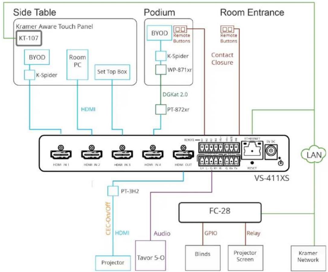
Thanks to out-of-the-box default configuration, VS-411XS is ready to control the following typical room configuration that can be controlled via several Maestro triggers.
flowchart
graph TD
    subgraph Side Table
        A["Kramer Aware Touch Panel KT-107"] --> B["BYOD"]
        B --> C["K-Spider"]
        C --> D["Room PC"]
        D --> E["Set Top Box"]
        E --> F["HDMI"]
    end

    subgraph Podium
        G["BYOD"] --> H["K-Spider"]
        H --> I["WP-871xr"]
        I --> J["DGKat 2.0"]
        J --> K["PT-872xr"]
    end

    subgraph Room Entrance
        L["Remote Buttons"] --> M["Contact Closure"]
        N["Remote Buttons"] --> O["Contact Closure"]
        P["Contact Closure"] --> Q["Contact Closure"]
    end

    R["VS-411XS"] --> S["PT-3H2"]
    S --> T["CEC-On/Off"]
    T --> U["HDMI"]
    U --> V["Projector"]
    W["FC-28"] --> X["Tavor 5-O"]
    X --> Y["Audio"]
    Y --> Z["Blinds"]
    Y --> AA["Projector Screen"]
    Y --> AB["Relay"]
    AC["Kramer Network"] --> AD["LAN"]

    style Side Table fill:#f9f,stroke:#333
    style Podium fill:#ccf,stroke:#333
    style Room Entrance fill:#cfc,stroke:#333
    style Side Table fill:#f9f,stroke:#333
    style Podium fill:#ccf,stroke:#333
    style Room Entrance fill:#cfc,stroke:#333
Figure 9: Typical Room Configuration
This room includes a podium, a side table, a projector, speakers, a projector screen, room blinds and so on, as follows:
| On the side table: | Three sources connected to VS-411XS HDMI inputs (for example, the Room PC, or a plugged-in device to connect to the K-Spider adapter cable).A KT-107 touch panel supporting Kramer aware and connected to the LAN. |
| Under the side table: | VS-411XS and FC-28 IP control gateway. |
| On the podium: | A BYOD source connected, via K-Spider adapter cable, to WP-871xr DGKat transmitter that is connected to the PT-872xr receiver.Remote buttons connected to the remote contact closure pins on the VS-411XS. |
| Next to the door near the entrance: | Remote buttons connected to the remote contact closure pins on the VS-411XS. |
| In the room: | VS-411XS HDMI output is connected to a projector via PT-3H2 HDMI extender, and audio output is connected to the Tavor 5-O speakers.The window blinds and projector screen are connected to GPIO/relay pins on the FC-28 IP control gateway. |
| LAN connections | VS-411XS, FC-28 IP control gateway, KT-107, and a Kramer Network control system. |
VS-411XS, built-in Maestro configuration enables almost immediate control over these elements for different scenarios, once all the elements in the room are connected (with minimal settings via built-in Maestro automation embedded web pages, such as device-specific IP addresses, see Configuring Device Control and Automation on page 41).
For example, the remote button on the podium, connected to the contact closure pin on VS-411XS, is defined as a trigger for starting a presentation.
Once the button is pressed, the PresentationStart, built-in script, runs a series of actions such as unmuting the audio and video outputs, turning the projector ON via CEC, lowering the screen rolling the blinds down, etc.
In this example, the projector is turned on via the CEC-TV port, relays on the FC-28 are activated via the Non-serial-onGW port (by defining the gateway IP address), and audio and video are unmuted by the internal port.
Factory default triggers, Scenarios, actions and ports are listed in Default Automation settings on page 62.
In addition to remote button triggers, the room can also be controlled via KT-107 touch panel buttons (see Maestro Kramer Aware Touch Panel Control on page 14), or a control station included in Kramer Network management (see www.kramerav.com/product/kramer%20network).
Maestro Kramer Aware Touch Panel Control
VS-411XS Maestro room control and automation includes a built-in default configuration for optional (purchased separately) Kramer Aware touch panel that includes all the essential buttons enabling room control.
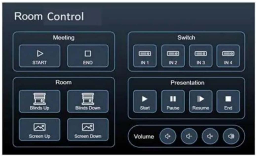
Figure 10: Default Kramer Aware Room Control Panel
You can add or remove elements from the panel (see Operating via Maestro Kramer Aware Touch Panel on page 45) or start using it immediately following minimal settings.
Operating and Controlling VS-411XS
Using Front Panel Buttons
Use the front panel to control VS-411XS. Press:
• IN buttons ② to select an input.
- VOL buttons to increase or decrease the buttons.
- MUTE to mute/unmute the audio output.
Setting DIP-Switches
The 4 DIP-switches ① located on the front panel are used for setting the switching mode and for CEC notifications.
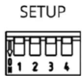
Figure 11: SETUP DIP-switches
All DIP-switches are set to Off (up) by default. DIP-switch changes take effect immediately.
| # | Feature | Dip-Switch Settings |
| 1 | Switching Mode | OFF (up) – Auto-switching mode.ON (down) – Manual mode. |
| 2 | Auto-switching Mode | OFF (up) – Last connected switching mode: the last detected active source is auto-switched to the output.ON (down) – Priority switching mode: the device switches the source with the highest priority to the output. |
| 3 | CEC Notifications | OFF (up) – CEC notifications enabled.ON (down) – CEC notifications disabled. |
| 4 | Reserved for Factory Use | It is mandatory to keep set to OFF (up). |
Using Contact Closure Remote Control Pins
The REMOTE terminal block connector includes input, volume and mute pins.
The contact closure remote control pins operate in a similar way to the front panel push buttons. Using the contact closure remote control (also known as push-to-make momentary contact) you can select an input, set the volume or mute the audio output.
If contact closure buttons are set to Custom (see Setting Remote Buttons on page 25) they are used to activate triggers that are set via Maestro (see Configuring Device Control and Automation on page 41).
You can connect remote, momentary-contact contact closure switches to the Remote 8-pin terminal block connector ^10 to control the unit.
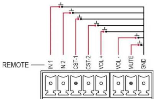
Figure 12: VS-211XS Remote Switches
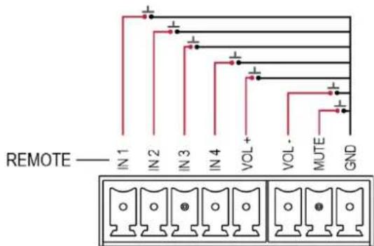
Figure 13: VS-411XS Remote Switches
| Connection | Function |
| IN | Select an input or alternatively activate custom triggers set up in Maestro:VS-211XS: by momentarily connecting IN 1, IN 2, CST-1 and CST-2 to GND.(Configured via the embedded web pages).VS-411XS: by momentarily connecting IN 1, IN 2, IN 3 and IN 4 to GND.(Configured via the embedded web pages). |
| VOL + | Increase audio output volume. |
| VOL- | Decrease audio output volume. |
| MUTE | Mute the output audio. |
| GND | Grounding connection. |

Do not connect more than one input pin to the G pin at the same time.
Acquiring and Discovering Plug-and-Play IP Address
By default, VS-411XS is DHCP-enabled, and the following Network settings are set:
- Fallback IP Address – 192.168.1.39
- Fallback Subnet Mask – 255.255.255.0
- Fallback Gateway – 192.168.1.1
To automatically acquire the IP address from DHCP server, connect VS-411XS to a LAN via Ethernet.
When connecting the device to LAN, the device discovers the DHCP server and then a new IP is acquired.
The fallback IP address (for first-time use) or the last-acquired IP address (for a device with an IP address other than the default) are maintained until a new IP address is acquired via DHCP server.

If DHCP server is not discovered, it attempts discovery every \~1 minute, while keeping the current IP address (fallback or last-acquired).
To renew DHCP discovery, perform factory reset via the RESET button ^12 Following reset and web-UI factory reset, the last acquired IP address is auto enabled.
Discovering IP Address
You can discover the IP address via any of the following ways:
• Discovering IP Address via Ethernet on page 17.
• Discovering IP Address by Performing Factory Reset on page 18.
• Discovering IP Address Router: on page 18.
• Discovering IP Address via RS-232 on page 18.
Discovering IP Address via Ethernet
To discover the IP address via the Ethernet:
- Connect your PC to the VS-411XS Ethernet port.
- Browse to the device unique hostname (e.g., http://VS-411XS-0024) to view its web-UI settings.

The Default hostname is: VS-411XS-xxxx (xxxx are the 4 last characters of the device serial ID).
-
Click Device Settings and then select Communication tab.
-
View current IP address.
IP address is discovered via Ethernet.
Discovering IP Address by Performing Factory Reset
To discover the IP address via factory reset:
- Connect your PC to the VS-411XS Ethernet port (in point-to-point connection, with no DHCP server connected).
- Press RESET 16 on the rear panel.
- Browse to default fallback IP address to view its web-UI settings.
- Click Device Settings and then select Communication tab.
- View current IP address.
IP address is discovered via factory reset.
Discovering IP Address Router:
To discover the IP address via router:
- Connect the VS-411XS Ethernet port to LAN subnet with a basic router supporting a built-in DHCP server and router web-UI.
- Open router web-UI to identify the device IP address via the router using its unique hostname and/or its MAC address.
IP address is discovered via router.
Discovering IP Address via RS-232
To discover the IP address via RS-232:
- Connect your PC to the VS-411XS RS-232 port (see Connecting to VS-411XS via RS-232 on page 9).
- Send the P3K #NET-IP?_
command (see Protocol 3000 Commands on page 70).
IP address is discovered via RS-232 port.
Operating via Ethernet
You can connect to VS-411XS via Ethernet using either of the following methods:
- Directly to the PC using a crossover cable (see Connecting Ethernet Port Directly to a PC on page 19).
- Via a network hub, switch, or router, using a straight-through cable (see Connecting Ethernet Port via a Network Hub on page 21).

If you want to connect via a router and your IT system is based on IPv6, speak to your IT department for specific installation instructions.
Connecting Ethernet Port Directly to a PC
You can connect the Ethernet port of VS-411XS directly to the Ethernet port on your PC using a crossover cable with RJ-45 connectors.

This type of connection is recommended for identifying VS-411XS with the factory configured default fallback IP address.
After connecting VS-411XS to the Ethernet port, configure your PC as follows:
- Click Start > Control Panel > Network and Sharing Center.
- Click Change Adapter Settings.
- Highlight the network adapter you want to use to connect to the device and click Change settings of this connection.
The Local Area Connection Properties window for the selected network adapter appears as shown in Figure 14.
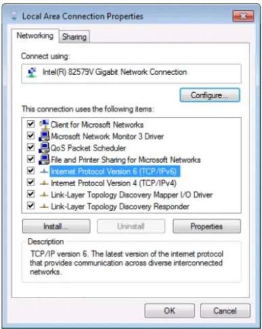
Figure 14: Local Area Connection Properties Window
-
Highlight either Internet Protocol Version 6 (TCP/IPv6) or Internet Protocol Version 4 (TCP/IPv4) depending on the requirements of your IT system.
-
Click Properties.
The Internet Protocol Properties window relevant to your IT system appears as shown in Figure 15 or Figure 16.
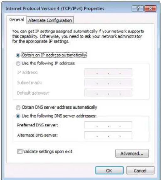
Figure 15: Internet Protocol Version 4 Properties Window
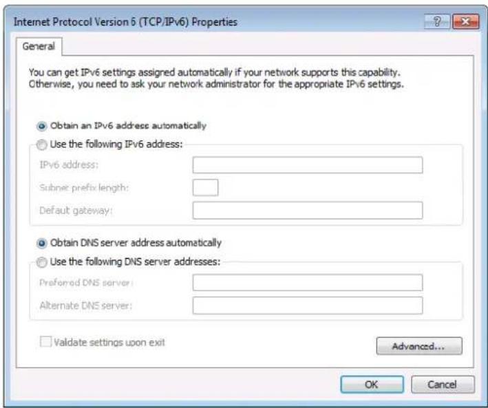
Figure 16: Internet Protocol Version 6 Properties Window
- Select Use the following IP Address for static IP addressing and fill in the details as shown in Figure 17.
For TCP/IPv4 you can use any IP address in the range 192.168.1.1 to 192.168.1.255 (excluding 192.168.1.39).
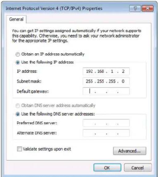
Figure 17: Internet Protocol Properties Window
- Click OK.
- Click Close.
Connecting Ethernet Port via a Network Hub or Switch
You can connect the Ethernet port of VS-411XS to the Ethernet port on a network hub or using a straight-through cable with RJ-45 connectors.
Configuring Ethernet Port
You can set the Ethernet parameters via the embedded Web pages.
Using Embedded Web Pages

This section describes the VS-411XS embedded web pages which applies also to the VS-211XS web pages.
VS-411XS can be operated remotely using the embedded Web pages. The Web pages are accessed using a Web browser and an Ethernet connection.
Before attempting to connect:
• Perform the procedures in Operating via Ethernet on page 18.
- Ensure that your browser is supported.
The following operating systems and Web browsers are supported:
| Operating Systems | Browser |
| Windows 10 | Chrome (Recommended) |
| Firefox | |
| Mac | Safari |
| iOS | Safari |
| Android | Chrome |

Some features might not be supported by some mobile device operating systems.
VS-411XS enables performing the following:
- Selecting an Input on page 23.
- Adjusting Audio Output Volume on page 24.
• Viewing and Adjusting General Settings on page 24. - Setting Remote Buttons on page 25.
- Loading and Saving Settings on page 25.
- Resetting Device on page 26.
• Defining IP Settings on page 27. - Define CEC Gateway Settings on page 29.
- Setting Time and Date on page 30.
• Upgrading the Firmware on page 31.
• Setting Security on page 32. - Setting Auto Switching Priorities on page 34.
- Setting Input Color Depth on page 34.
-
Setting Output Audio Source for De-embedded Audio on page 35.
• Setting HDCP Support on page 35. -
Setting Video Signal Timeouts on page 37.
• Managing EDID on page 38. - Configuring Device Control and Automation on page 41.
• Viewing About Page on page 59.
To use the browser:
- Open your Internet browser.
- Type the IP number of the device, or its hostname, in the Address bar of your browser. For example, the default fallback IP address or default host name (see Discovering IP Address via Ethernet on page 17):

The device operation page appears.
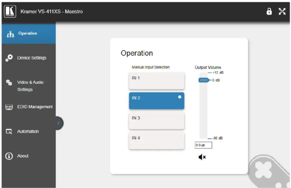
Figure 18: Operation Page with Navigation List on Left
- Click the tabs on the left side of the screen to access the relevant web page.
Selecting an Input
You can manually select an input. Manual selection via the front panel buttons or the embedded webpage overrides the auto-switching mode.
To select an input:
- Click Operation on the Navigation List.
The Operation page appears (Figure 18). - Click an IN button.
The input is selected and the button on the front panel is lit.
Adjusting Audio Output Volume
You can adjust the VS-411XS output volume.
To adjust the audio output volume:
- Click Operation on the Navigation List. The Operation page appears (Figure 18).
- Use the Output Volume slider to adjust the volume or enter audio level value in the text box below the slider.
- View audio mute status (unmute/mute) or click to change the status.

The audio signal remains mute when decreasing the volume and unmutes automatically when increasing the volume.
The output audio volume is adjusted.
Viewing and Adjusting General Settings
To view and adjust general settings:
- Click Device Settings on the Navigation List. The General tab in the Device Settings page appears.
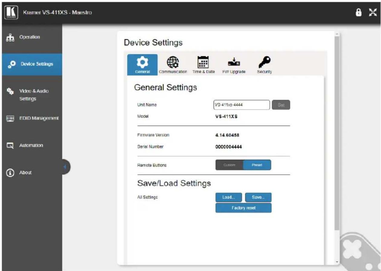
Figure 19: Device Settings Page – General Settings
- Next to Unit Name, enter the device name and click Set.
- View model name, firmware version and serial number.
General settings are viewed/set.
Setting Remote Buttons
You can define the function of the REMOTE contact closure pins (see Using Contact Closure Remote Control Pins on page 16).
To define the REMOTE contact closure buttons:
- Click Device Settings on the Navigation List.
The General tab in the Device Settings page appears (Figure 19). - Next to Remote Buttons, define button functionality.
- Preset – Maintains PINs default functionality.
- Custom – All PINs act as GPI/O inputs and are configured via Maestro (see Configuring Device Control and Automation on page 41).

For VS-211XS, CST-1 and CST-2 are GPI/O inputs by default.
REMOTE PIN functionality is defined.
Loading and Saving Settings
VS-411XS enables saving the current configuration settings (such as all the Maestro settings, auto-switching settings, audio level and audio settings, and so on) for easy configuration duplication on similar systems or recall in the future.
Saving Configurations
To save a configuration:
-
Click Device Settings on the Navigation List.
The General tab in the Device Settings page appears (Figure 19). -
Click Save. The device saves the configuration and then the Download File message appears.
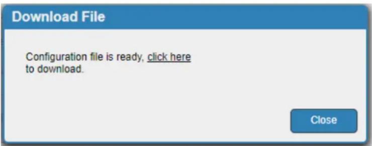
Figure 20: General Settings – Download File Message
- Click click here to download the file.
- Click Close.

When using Chrome, the file is automatically saved in the Downloads folder.
Current Settings are Saved.
Loading Configurations
To load a configuration:
- Click Device Settings on the Navigation List.
The General tab in the Device Settings page appears (Figure 19). - Click Load.
An Explorer window opens. - Select the required file and click Open.
The device is configured according to the saved preset.
Resetting Device
You can reset the device to its default parameters, including model name and network settings (such as TCP/UDP port numbers, IP address and so on).
To reset the device to its factory default parameters:
- Click Device Settings on the Navigation List.
The General tab in the Device Settings page appears (Figure 19). - Click Factory reset. The Communication warning appears.
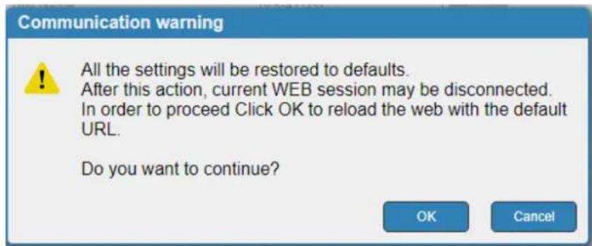
Figure 21: General Settings – Communication Warning
- Click OK.

Following factory reset, the device resets to DHCP ON. If no DHCP server is found, the device falls back to its default fallback IP settings (see Acquiring and Discovering Plug-and-Play IP Address on page 17 and Default Communication Parameters on page 62).
The device resets to its default parameters.
Defining IP Settings
By default, VS-211XS is DHCP enabled (see Discovering IP Address on page 17 for discovering the IP address). If a DHCP server is not available, the device falls-back to the default IP address (see Default Communication Parameters on page 62). you can change the IP settings as required via the embedded web pages.
Disabling DHCP
To Disable DHCP:
- Click Device Settings on the Navigation List.
- Select Communication tab.
Device Settings

General

Communication

Time & Date

FW Upgrade

Security
IP Settings
DHCP
IP address
Mask address
Gateway address
ON
OFF
192 168 1 39
255.255.255.0
192.168.1.2
Set
Mac address
UDP port
TCP port
00-1d-56-03-8d-13
50000
5000
Set
Set
CEC Settings
CEC gateway
Members address list
ON
OFF
[14]
Refresh
Figure 22: Device Settings Page – Communication Tab
- Click OFF next to DHCP. The DHCP message appears.
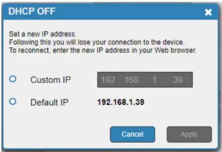
Figure 23: Communication Tab-DHCP OFF Message
- Check Custom IP (and enter the address) or Default IP.
- Click Apply. The webpage reloads.
- Enter the required IP settings.
- Click Set.
DHCP is disabled.
Enabling DHCP
To enable DHCP
- Click Device Settings on the Navigation List.
- Select Communication tab.
- Click ON next to DHCP. A communication warning appears.
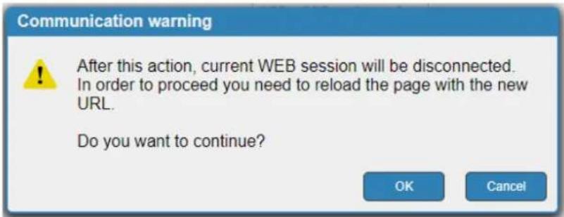
Figure 24: Communication Tab – Communication Warning Message
- Click OK.
DHCP is enabled.
Changing TCP/UDP Port Numbers
By default, TCP/UDP port numbers are set to 5000/50000 respectively.
To change the port numbers:
- Click Device Settings on the Navigation List (Figure 22).
- Select Communication tab.
- Enter the new port number or use the up/down arrows to set the new port number.
- Click Set.
Port numbers have changed.
Define CEC Gateway Settings
VS-411XS built-in CEC gateway enables IP control of control system, via CEC messages, on HDMI connected devices to the selected input and the output port (see IP-Driven CEC Signals Routing via Built-in Control Gateway on page 11). The Members address list shows the logical addresses of connected CEC-enabled devices.

By-default, CEC gateway is enabled.
To disable CEC gateway feature:
- Click Device Settings on the Navigation List (Figure 22).
- Select Communication tab.
- Click CEC gateway OFF.
CEC gateway is disabled.
You can view the logical addresses of CEC-enabled devices that are connected via HDMI output port to VS-411XS and click Refresh to refresh the list.
Setting Time and Date
You can set a device time and date manually or Sync the device time and date to any server around the world.
To set device time and date manually:
- In the Navigation pane, click Device Settings.
- Select the Time & Date tab. The Time & Date tab appears.
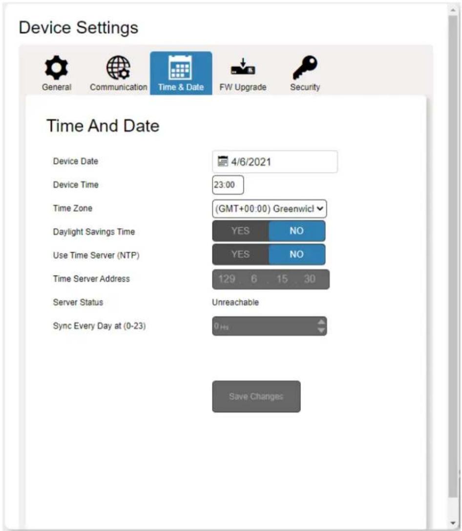
Figure 25: Device Settings Page – Time and Date Tab
- Next to Use Time Server (NTP), click NO. Device time & date fields are enabled and network fields are disabled.
- Set the device date and time manually.
- Select the time zone.
- Click Save Changes.
The devices date and time are set.
To sync device time and date to a server:
- In the Navigation pane, click Device Settings.
- Select the Time & Date tab. The Time & Date tab appears (Figure 25).
-
Next to Use Time Server (NTP), click YES to use time server (NTP).
Device Time & Date Fields are disabled, and network fields are enabled. -
Type in server information:
-
Enter the address.
-
Set sync schedule.
-
Click Save Changes.
The devices date and time are synchronized to the server address entered.
Upgrading the Firmware
As features are added, new firmware versions are released for downloading on the Kramer website.
To upgrade the firmware:
- In the Navigation pane, click Device Settings.
- Select the FW Upgrade tab. The FW Upgrade tab appears.
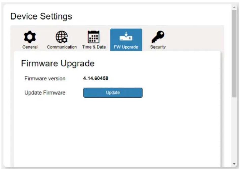
Figure 26: Device Settings Page – Firmware Upgrade tab
- Click Update. The Windows Browser opens.
-
Browse to the required file and click Open. The firmware file name is displayed in the Firmware Upgrade tab.
-
Click Start Upgrade. The firmware file is loaded, and a progress bar is displayed.

Do not interrupt the process or the VS-411XS may be damaged.
- When the process is complete reboot the device.
The firmware is upgraded.

You can upgrade firmware for multiple VS-411XS devices installed in the organization via Kramer Network.
Setting Security
The Security tab enables activating device security and defining logon authentication details. When device security is enabled, web page access requires authentication upon initial landing on operation page. The default password is Admin. The upper right corner of the webpage displays for indicating whether authentication is required. By default, security is enabled.
To disable security:
- In the Navigation pane, click Device Settings.
- Select Security tab. The Security tab appears.
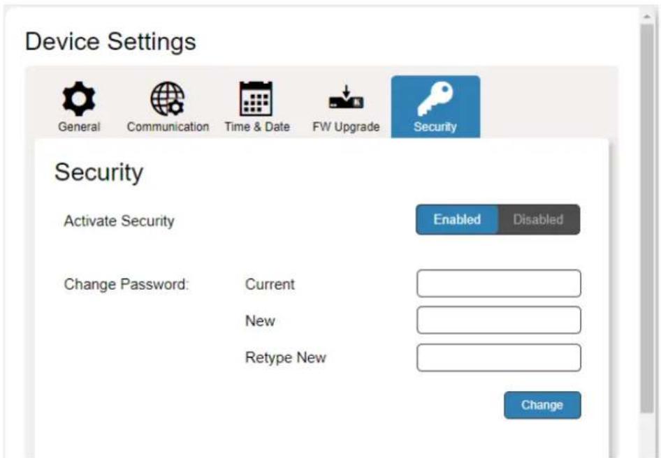
Figure 27: Device Settings – Security Enabled
- Click Disabled. A Confirmation message appears.
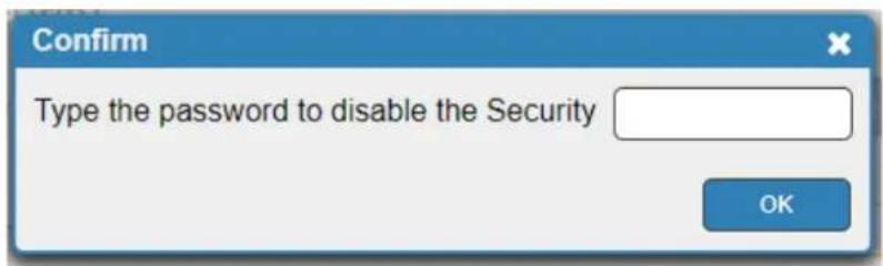
Figure 28: Security Tab – Confirmation Message
-
Enter the Password (Admin, by default).
-
Click OK. The password fields disappear, and the upper right icon changes to Security is disabled.
To enable security:
- In the Navigation pane, click Device Settings.
- Select Security tab.
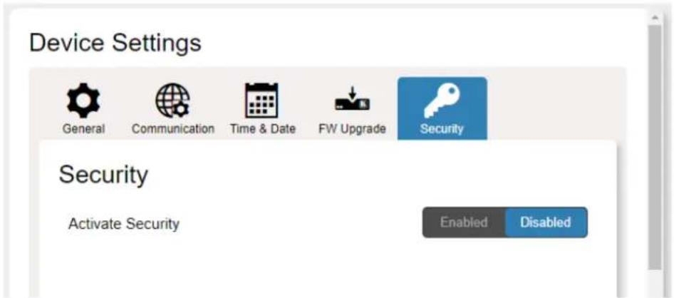
Figure 29: Device Settings – Security Tab
- Click Enabled. A warning message appears.
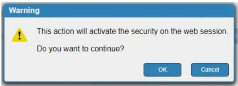
Figure 30: Security Tab – Warning Message
- Click OK. The web page refreshes, and the password fields are visible.
- If required, type the current password and new password twice and click Change.
The upper right icon changes to
Security is enabled.
Setting Auto Switching Priorities
By default, VS-411XS is set via the SETUP DIP-switches (see Setting DIP-Switches on page 15) to auto-switching, last-connected switching mode. You can view current switching mode and change switching priorities (applicable to Priority mode only) via the embedded web pages.
To change switching priorities:
- In the Navigation pane, click Video & Audio Settings.
- View the video selection mode.
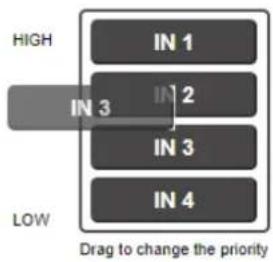
- Drag and drop inputs to set which inputs get higher priority.
Video auto switching priority
flowchart
graph TD
    A["IN 1"] --> B["IN 2"]
    C["IN 3"] --> D["IN 3"]
    E["IN 4"] --> F["IN 4"]
    G["High"] --> H["IN 3"]
    I["Low"] --> J["IN 3"]
    K["Drag to change the priority"]
Figure 31: Dragging Input to Change Priority
The video inputs priority changes.
Setting Input Color Depth
VS-411XS enables setting the color depth per input.
To Set the Color Depth on an input:
- In the Navigation pane, click Video & Audio Settings.
- Next to each input, click one of the following:
■ Follow Output (default), to follow the output color depth.
■ Force 8-bit color graphics.
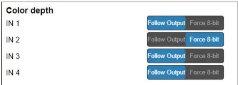
Figure 32: Video & Audio Settings – Color Depth
Color Depth is defined.
Setting Output Audio Source for De-embedded Audio
2-channels of non-encrypted output HDMI audio are de-embedded and are output to the AUDIO OUT ^10
To set output audio source:
- In the Navigation pane, click Video & Audio Settings.
-
Next to De-embedded audio output, click one of the following:
-
Forward (default), to output audio of the switched HDMI input, forward to the display.
- ARC, to output HDMI ARC (Audio Return Channel) audio, returned backwards from the display.
Audio
De-Embedded audio output:
Forward
ARC
Figure 33: Video & Audio Settings – Audio ARC

- ARC signal passes between the output display and the switched input source (excluding VS-411XS IN 4).
- The audio source is output to the speakers connected to AUDIO OUT in parallel to its traversal to/from the display.
Output audio source is set.
Setting HDCP Support
There are video sources (e.g., some Apple devices) that automatically switch to HDCP protected mode if connected to a device that supports HDCP (e.g. VS-411XS) protection. You can set HDCP support modes on both the inputs and the output.
For example, if an acceptor connected to VS-411XS output does not support HDCP protection, you might want to disable input HDCP support, so that the video source does not auto-switch to HDCP-protected mode and driving no video display on the output acceptor.
Other HDCP support options are available, allowing flexible support according to HDCP compatibility needs between the input sources and output acceptor.
To set input HDCP support:
- In the Navigation pane, click Video & Audio Settings.
The Video & Audio Settings page appears.
- Click Enabled (default)/ Disabled for each input.
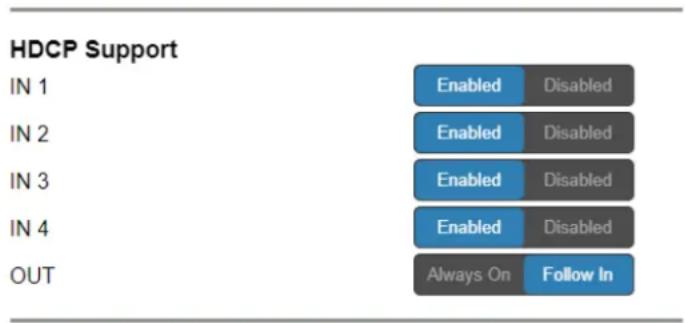
Figure 34: Video & Audio Settings – HDCP Support
Input HDCP support is set.
To set output HDCP support:
- In the Navigation pane, click Video & Audio Settings.
The Video & Audio Settings page appears.
- Click Always On /Follow In (default).
Output HDCP support is set.
Setting Video Signal Timeouts
VS-411XS enables setting the time delay before triggering auto-switching and display auto-sleep entry.
To set the timeout for auto-switching video inputs if signal is lost:
- In the Navigation pane, click Video & Audio Settings.
- Under "When the HDMI signal is lost, leave 5V power ON and delay switching for" set the delay time 0-905 seconds (where 0 is no timeout, 10 is the default).
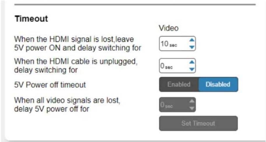
Figure 35: Video & Audio Settings – Timeouts
3. Click Set Timeout.
Auto-switching on signal-lost timeout is set.
To set the timeout for auto-switching video inputs for unplugged HDMI cable:
- In the Navigation pane, click Video & Audio Settings.
- Under "When the HDMI cable is unplugged, delay switching for" set the delay time 0-905 seconds (where 0 is no timeout and the default).
- Click Set Timeout.
Auto-switching on cable-unplug timeout is set.
To set display auto-sleep entry no AV signal is detected:
- In the Navigation pane, click Video & Audio Settings.
- Next to "5V Power off timeout" click Enabled. The timeout field beneath the button is enabled.
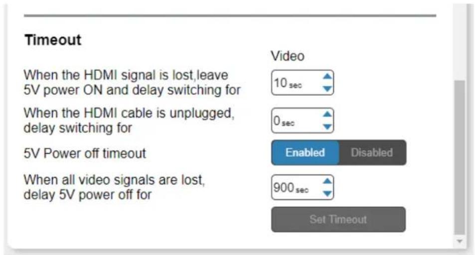
Figure 36: Video & Audio Settings – 5V Power Off Timeout
- Under "When all video signals are lost, delay 5V power off for" set the delay time from 30-60,000 seconds (where 900 is the default).
Display auto-sleep entry timeout is set.
Managing EDID
VS-411XS enables copying EDID data to either one or several inputs (for use by the connected sources) from the following EDID sources:
- Inputs
- Output
- Default EDID
- Custom EDID data file

When the status of an EDID changes on the device (caused by outputs being exchanged), the display is not updated automatically. In the browser, click Refresh to update the display.

An input must be connected to the device to read the EDID from a connected output. If a video signal is not detected on the input, the output is disabled and the EDID cannot be read
The selected EDID can be copied to the selected input/s.

View the currently selected EDID source Bytemap by clicking Bytemap on the right side.
To copy an EDID from an output / input to an input:
- In the Navigation pane, click EDID Management.
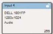
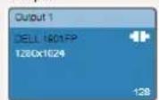
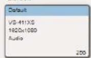
- Select the EDID source (for example, the output).

If you are reading EDID from an output, make sure that that output is connected to an acceptor.
- Select one or more inputs.
EDID Management
Read from
Input
Copy to
Un/Select All □
Output
Default
Custom



Figure 37: EDID Management Page – Copying EDID from the Output
- Click COPY.
The EDID is copied to the selected inputs.
To read the EDID from the default EDID:
- In the Navigation pane, click EDID Management.
- Click Default.
- Select one or more inputs.
EDID Management
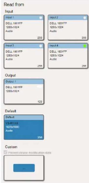
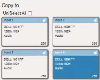

Figure 38: EDID Management Page – Copying Default EDID
4. Click COPY.
The default EDID is copied to the selected inputs.
To import a customized EDID file:
- In the Navigation pane, click EDID Management.
- Click Custom. The Windows Browser opens.
- Select the custom EDID file and click Open. The file is selected.
- Select one or more inputs and click COPY.
The custom EDID file is copied to the selected inputs.
Configuring Device Control and Automation
Use the Automation page to access built-in Kramer Maestro V1.5 room control and automation. Maestro is a powerful built-in tool that enables you to configure triggers for room control and automation scenarios without the need for complicated programming. To use Maestro control and automation, you need to define triggers that, upon an event, will execute scripts which include a sequence of actions (commands, which can appear in different scenarios) that will be carried out via any defined ports.
Download the Kramer Maestro User Manual from the Kramer web site at www.kramerav.com/downloads/VS-211XS or www.kramerav.com/downloads/VS-411XS to learn how to use Kramer Maestro.

Note that all the ports, actions and triggers that are relevant to VS-411XS are included in the Kramer Maestro, as well as ports, actions and triggers that are relevant to other Kramer devices.
Configuring Ports
Maestro enables configuring the ports used to control specific room devices.
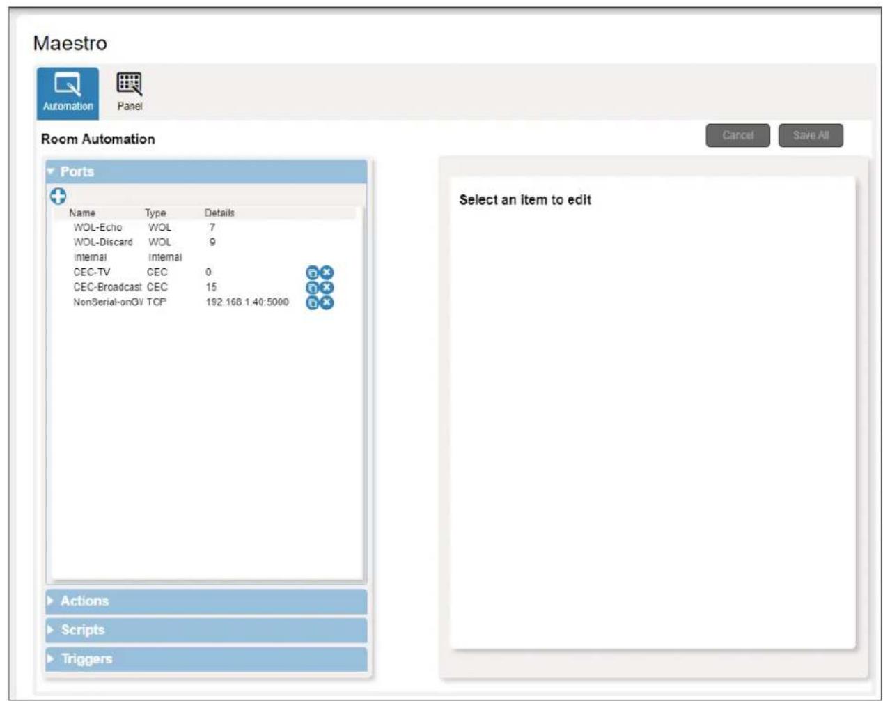
Figure 39: Automation Page – Ports List
In this example, VS-411XS is connected to Kramer FC-28 control gateway (optional, purchased separately). FC-28 includes various serial and non-serial ports and is set, for example, to IP Address 192.168.1.40.
VS-411XS includes the following default ports:
| Port Name | Type | Port Properties | Port Description | Comments |
| WOL-Echo | WOL | 7 | ||
| WOL-Discard | WOL | 9 | ||
| Internal | Internal | Enabling actions on the device itself, such as switching an input. | ||
| CEC-TV | CEC | 0 | Enabling actions such as display on/off. | |
| CEC-Broadcast | CEC | 15 | ||
| Non-Serial-on-GW | TCP | 192.168.1.40, 5000 | Gateway Non-serial ports | For example, Relay, GPIO and IR control on the FC-28 gateway. |
You can add ports to Maestro (see www.kramerav.com/downloads/VS-211XS) for example, if VS-411XS is connected to FC-28, you can add, for example, gateways for the two RS-232 serial ports on the FC-28.
| Port Name | Type | Port Properties | Port Description | Comments |
| Display-Serial1-on-GW | TCP | 192.168.1.40, 5001 | FC-28 gateway; RS-232 1 port | |
| Serial 2-on-GW | TCP | 192.168.1.40, 5002 | FC-28 gateway: RS-232 2 port |
Configuring Actions
In the Actions tab you can create new commands, and also view and edit the default commands (see Actions List on page 62) that are device specific.
Maestro
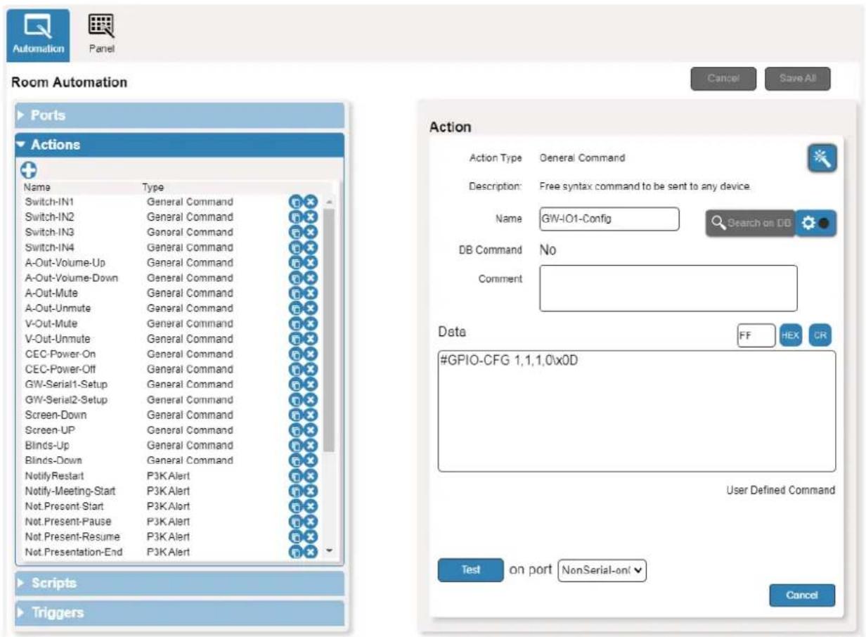
Figure 40: Automation Page – Actions List
You can add actions by duplicating an action from the list of built-in actions and changing it as required, or by a creating new action altogether (see www.kramerav.com/downloads/VS-211XS).
Configuring Scripts
A script includes several actions. You can add commands to an existing script, create new scripts or use the available built-in scripts (see Scripts List on page 64). For example, click the PresentationStart script to view its list of actions.
Maestro
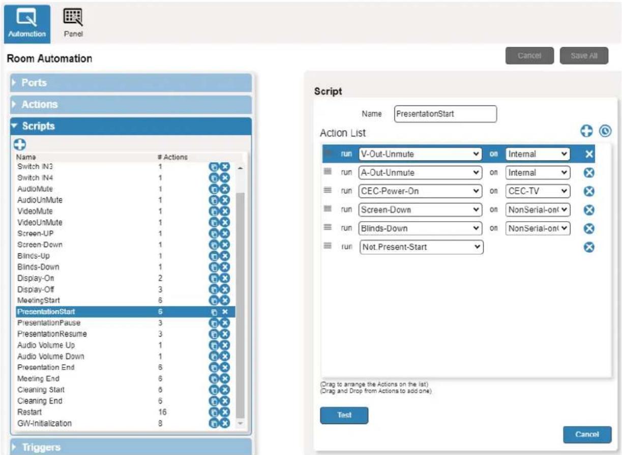
Figure 41: Automation Page – Scripts List
You can add, delete, or change the order of the actions in the list.
Configuring Triggers
The trigger is a predefined event that, when activated, causes the script associated to it to run. For example, click the built-in First_IN_Plugged trigger that triggers the PresentationStart script so that when an active input signal is detected, the PresentationStart script runs automatically. See default list of triggers in (see Triggers List on page 66).
Maestro
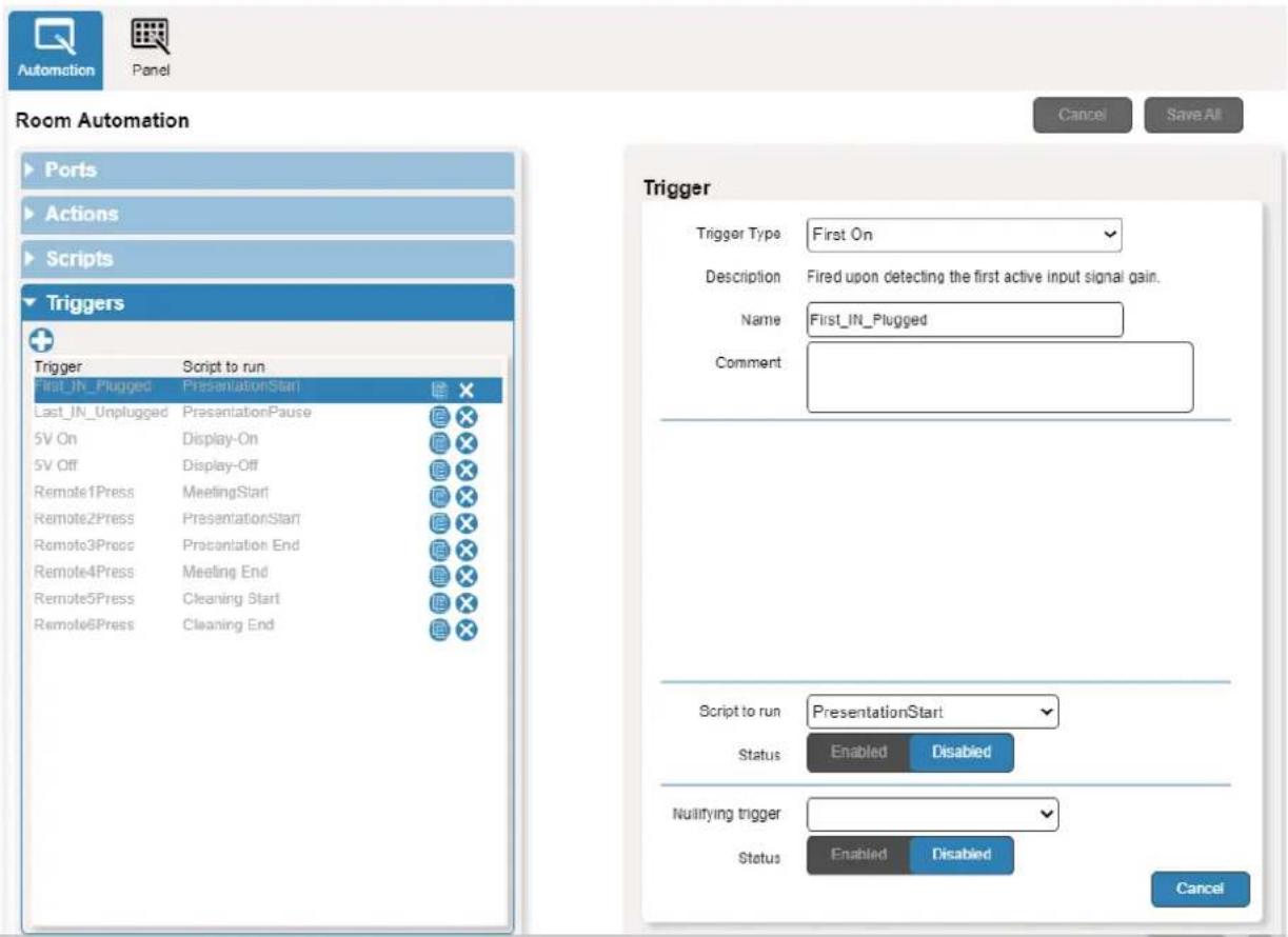
Figure 42: Automation Page – Triggers List
You can add, delete, or modify a trigger (see www.kramerav.com/downloads/VS-211XS).
Operating via Maestro Kramer Aware Touch Panel
You can control VS-411XS via any of Kramer's Kramer Aware app. touch panels (for example, KT-1010).

Kramer touch panels are purchased separately.
VS-411XS enables performing the following actions:
- Viewing and carrying out actions via the control panel in the Automation Page.
- Editing the device control panel.
Viewing and Executing Actions Via Maestro Control Panel
Before connecting to a designated Kramer Aware touch panel, you can view the Maestro default control panel and ensure the buttons are active and are suited for your needs.
To view and execute actions via the control panel:
- In the Navigation pane, click Automation. The Automation page appears (see Figure 39).
- Click the Panel tab (by-default, in Action mode). The default VS-411XS Maestro Room Control panel appears.
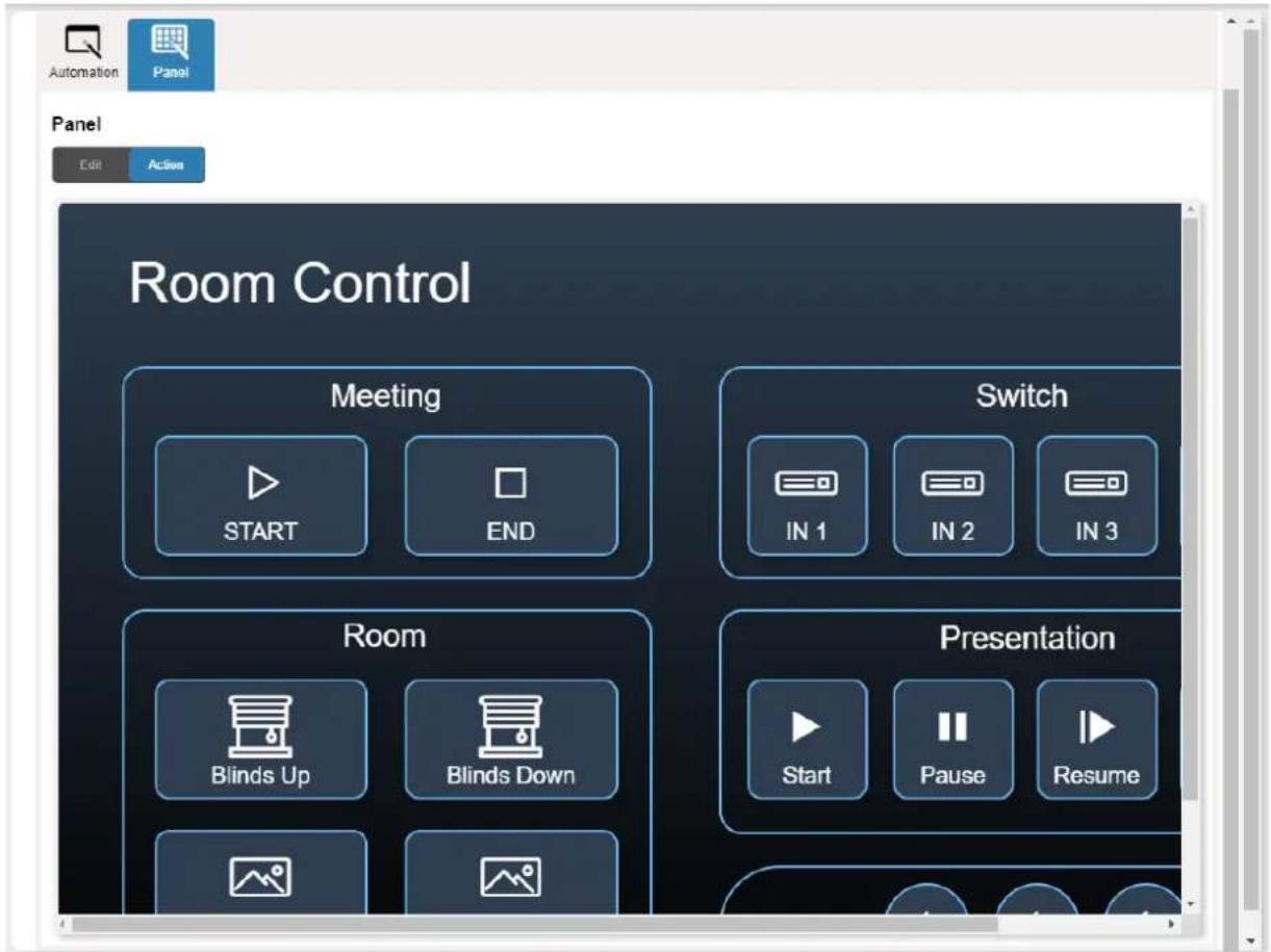
Figure 43: Automation Page – Panel Tab

The resolution of the panel fits the designated Kramer Aware touch-panel, therefore it appears in large-scale.
-
Perform the following actions:
-
Click meeting Start / End to prepare the room for a meeting (as specified in the Maestro scripts).
■ Switch one of the four inputs.
■ Control room blinds and screen Up / Down.
■ Play and control a presentation.
■ Control the audio output.
Configuring Device Control Panel
The default Maestro room control panel items can be configured to suit your needs. Each item on the panel can be modified and new items can be added. The Edit Panel window includes a display of the current Maestro control panel, the properties area to the right, the Object List below and three Add buttons to add new items to the panel next to the Object List.
The VS-411XS Room Control Panel enables performing the following actions:
- Selecting Panel Model on page 48.
- Setting Panel Background on page 49.
- Defining Panel Configuration Grid on page 49.
• Modifying a Button on page 49. - Modifying Text on page 51.
• Modifying a Frame on page 53. - Adding a New Button on page 54.
- Adding a New Text Field on page 56.
- Adding a New Frame on page 57.
Selecting Panel Model
To select the panel model:
- In the Navigation pane, click Automation. The Automation page appears (see Figure 39).
- Click the Panel tab. The default VS-411XS Maestro Room Control panel appears (see Figure 43).
- Click Edit. Edit Panel window appears, showing the General Properties area.

You can also access General Properties by clicking the background panel area.
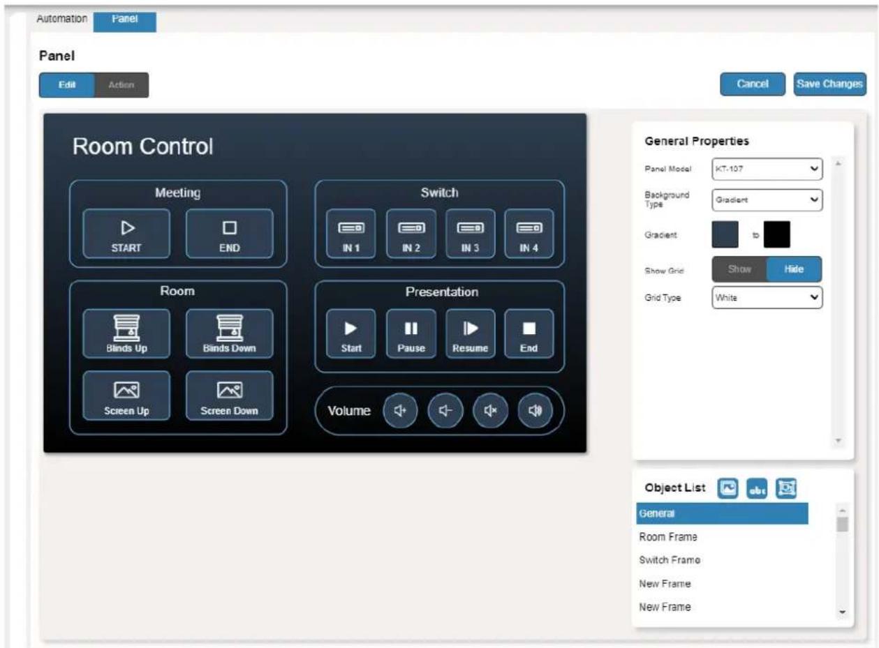
Figure 44: Automation Page – Editing Panel Window
- From Panel Model drop-down list (in General Properties), define the panel model. If Custom is selected, set Panel Size (in pixels).
- Click Save Changes.
Panel model is defined.
Setting Panel Background
You can select the background color and configure the background pattern.
To configure the panel background:
- In the Navigation pane, click Automation. The Automation page appears (see Figure 39).
- Click the Panel tab. The default VS-411XS Maestro Room Control panel appears (see Figure 43).
- Click Edit. Edit Panel window appears (see Figure 44).
-
In General Properties area set the Background Type:
-
Solid – Click Background Color button to select the color.
- Gradient – Click Gradient color buttons to select the gradient.
- Pattern – Select the pattern colors, type, and sizes.
- Image – Click Upload Image button to select an image file.
Defining Panel Configuration Grid
The background grid helps align each configured item in the panel. You can show and hide the grid and select its color for your convenience.
To define the grid:
- In the Navigation pane, click Automation. The Automation page appears (see Figure 39).
- Click the Panel tab. The default VS-411XS Maestro Control Panel appears (see Figure 43).
- Click Edit. Edit Panel window appears (see Figure 44).
- Click Show to show grid.
- From Grid Type drop-down box, select the grid color.
The configuration grid is defined.
Modifying a Button
The default device control panel includes several buttons (for example, the Volume Up button) that can be modified.
To modify a button:
- In the Navigation pane, click Automation. The Automation page appears (see Figure 39).
- Click the Panel tab. The VS-411XS Maestro Control Panel appears (see Figure 43).
-
Click Edit. Edit Panel window appears (see Figure 44).
-
Click the relevant button (in this example, Volume UP appears in the Object List). Volume UP button is selected in the device control panel.
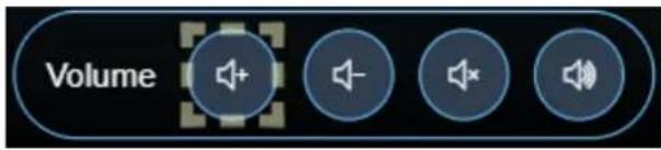
Figure 45: Edit Panel – Volume Up button Selected
The Properties (Button) and Volume UP Object list appear:
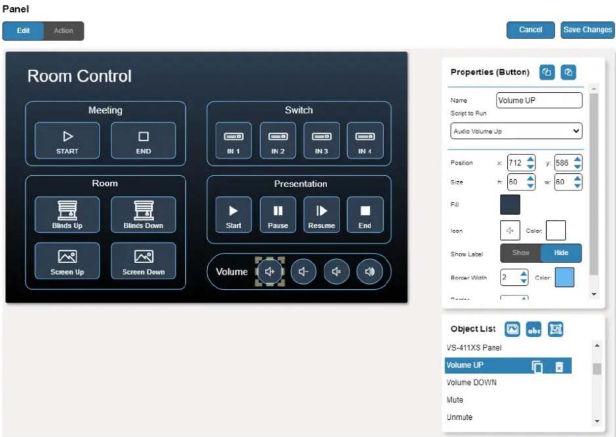
Figure 46: Edit Panel – Properties (Button) Area
-
Next to Volume UP, do any of the following:
-
Click to duplicate the button.
-
Click to remove the button.
-
In the Properties (Button) area, perform any of the following actions:
-
Click 📋 to copy the selected button properties (Fill, Icon Color, Label Size and Color Border Color, Border Width and Color, and Border Radius).
- Click to paste button properties to a selected frame.
- Change the button name.
- Select the script to run when this button is pressed.
- Set the position of the button by moving the button (or by entering the x, y position).
-
Enter button Size to change h and w button size (or use up/down arrows).
-
Click the Fill color button to change the button color.
- Change the button Icon and select its Color.
- Click Show/Hide to show or hide the frame.
- Enter Border Width to change the button border width (or use up/down arrows).
- Click border Color button to select border color.
- Enter Border Radius to change the border edge radius (or use up/down arrows).
7. Click Save Changes.
This button is configured.
Modifying Text
The Maestro Control panel includes Text (for example, Presentation). You can modify a button, using the Panel Edit tab.
To modify the text:
- In the Navigation pane, click Automation. The Automation page appears (see Figure 39).
- Click the Panel tab. The VS-411XS Maestro Control panel appears (see Figure 43).
- Click Edit. Edit Panel window appears (see Figure 44).
- Click the relevant Text Field, for example, Presentation (in this example, Presentation appears in the Object List).
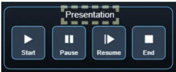
Figure 47: Edit Panel – Text Field Selected
The Properties (Text Field) and NewTextField Object list appear:
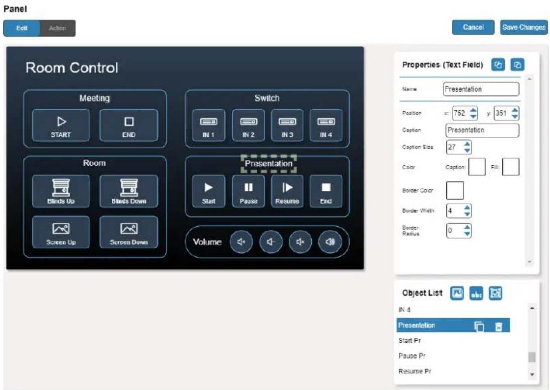
Figure 48: Edit Panel – Properties (Text Field) Area
-
Next to Presentation, do any of the following:
-
Click next to duplicate the text field.
-
Click to remove the text field.
-
In the Properties (Text Field) area, perform any of the following actions:
-
Perform any of the following actions:
-
Click 📋 to copy the selected text field properties (Caption Size, Caption and Fill Color, Border Width and Color, and Border Radius).
- Click to paste button properties to a selected Text Field.
■ Change the text field name. - Set the position of the button by moving the button (or by entering the x, y position).
- Enter the caption.
- Enter Caption Size (or use up/down arrows).
- Click the Caption and Fill colors to change them.
- Change the button Icon and select its Color.
- Click Border Color button to select border color.
- Enter Border Width to change the border width (or use up/down arrows).
-
Enter Border Radius to change the border edge radius (or use up/down arrows).
-
Click Save Changes.
Presentation text field is configured.
Modifying a Frame
The default Maestro Control panel includes several frames (for example, the Video Frame) that can be modified via the Edit Panel tab.
To modify a frame:
- In the Navigation pane, click Automation. The Automation page appears (see Figure 39).
- Click the Panel tab. The VS-411XS Maestro Room Control panel appears (see Figure 43).
- Click Edit. Edit Panel window appears (see Figure 44).
- Click the relevant frame (in this example, Switch Frame appears in the Object List). Video frame is selected in the control panel.
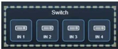
Figure 49: Edit Panel – Video Frame Selected
The Properties (Frame) and Video Frame Object list appear:
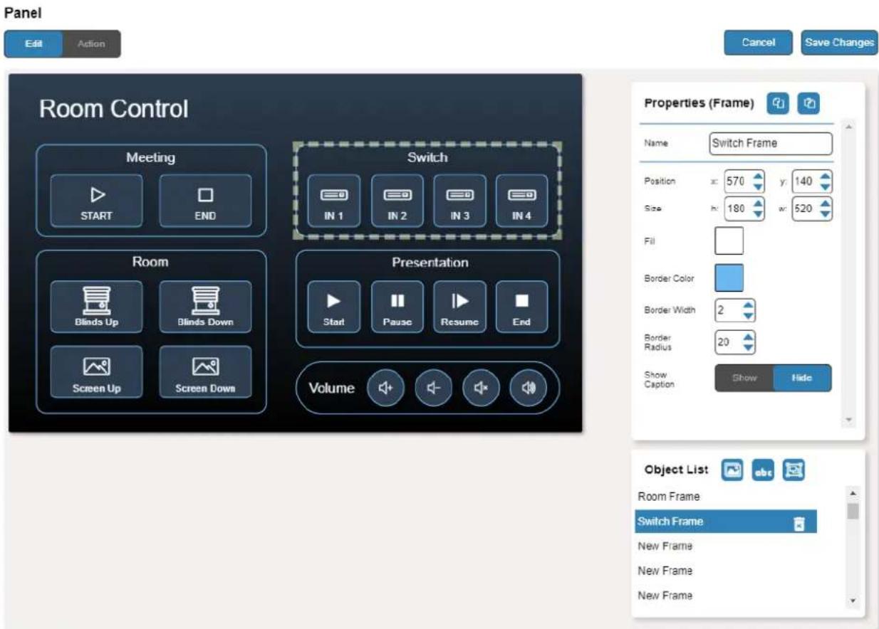
Figure 50: Edit Panel – Properties (Button) Area
-
Click next to Video Frame to remove the frame from the panel.
-
In the Properties (Frame) area, perform any of the following actions:
-
Click 📋 to copy the selected frame properties (Fill, Border Color, Border Width and Border Radius).
- Click to paste frame properties to a selected frame.
- Change the frame Name.
- Set the position of the frame by moving it (or by entering the x, y coordinates).
- Enter frame size (or click Size up/down arrows to change h and w frame size).
- Click the Fill color button to change the frame color.
- Click the Border Color button to change the border color.
- Enter Border Width to change the border width (or use up/down arrows).
- Enter Border Radius to change the border edge radius (or use up/down arrows).
- Click Show/Hide to show or hide the frame.
7. Click Save Changes.
The frame is configured.
Adding a New Button
The buttons in the Maestro Control panel are designed to carry out an assigned script to run when that button is pressed.
To add a new button:
- In the Navigation pane, click Automation. The Automation page appears (see Figure 39).
- Click the Panel tab. The default VS-411XS Maestro Control panel appears (see Figure 43).
-
Click Edit. The Edit panel appears (see Figure 44).
-
Click (add a button object) to add a new button to the panel. A new button is added to the top left side of the panel.
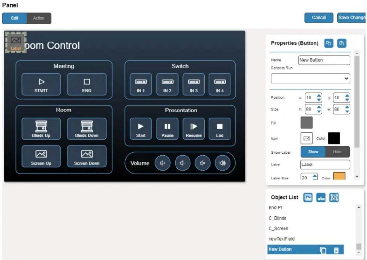
Figure 51: Adding a New Button
- Enter the button name. For example, use "Meeting Off" to turn off the devices in the room when a meeting ends.
- Assign a script (for example, Restart) to this button from the drop-down list.
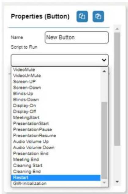
Figure 52: New Button – Assigning a Script
- Design the button appearance by selecting the button:
■ Position and size.
■ Background fill.
■ Icon and icon color.
- Click Show/Hide to show or hide the button.
When showing the Caption, define label text, size, and color.
-
Enter the Label, label size and color.
-
Define the border width, color, and radius.
-
Click Save Changes.
A new button is added.
Adding a New Text Field
The Text Field in the Maestro Control panel is designed to give a title to a group of buttons.
To add a new text field:
- In the Navigation pane, click Automation. The Automation page appears (see Figure 39).
- Click the Panel tab. The default VS-411XS Maestro Control panel appears (see Figure 43).
-
Click Edit. The Edit panel appears (see Figure 44).
-
Click (add a text field) to add a new text field to the panel. A new text field is added to the top left side of the panel.
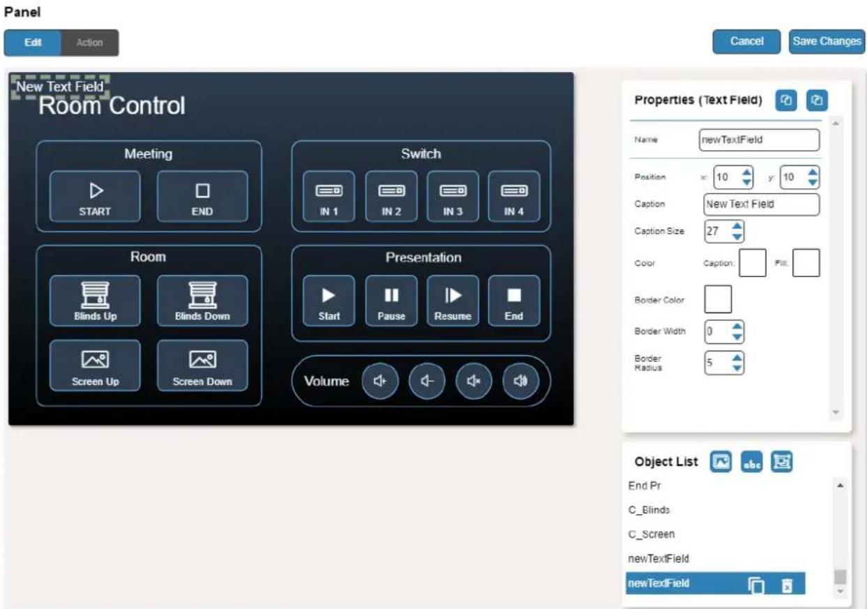
Figure 53: Adding a New Text Field
- Enter the text field name. For example, use "Meeting Space" to define meetings on/off area.
- Enter the text caption.
- Design the text field appearance by selecting its:
■ Position and size.
- Caption color and background fill.
■ Border width, color and radius.
- Click Save Changes.
A new text field is added.
Adding a New Frame
The frame in the Maestro Control panel is designed to encircle a group of buttons.
To add a new frame:
- In the Navigation pane, click Automation. The Automation page appears (see Figure 39).
-
Click the Panel tab. The default VS-411XS Maestro Control panel appears (see Figure 43).
-
Click Edit. The Edit panel appears (see Figure 44).
-
Click (add a frame) to add a new frame to the panel. A new frame is added to the top left side of the panel.
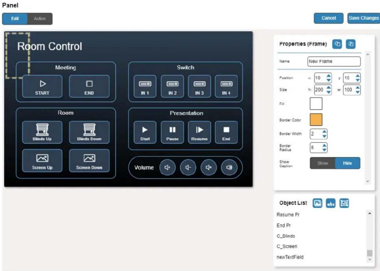
Figure 54: Adding a New Frame
- Enter the frame name. For example, use "Meeting frame" to define meetings on/off area.
- Design the frame appearance by selecting its:
■ Position and size.
■ Border color and background fill.
■ Border width and radius.
- Click Show/Hide to show or hide the frame. When showing the Caption, define:
■ Caption text and size.
- Caption text color, background color and border color.
- Caption offset.
- Click Save Changes.
A new frame is added.
Viewing About Page
View the Web page version and Kramer Electronics Ltd details in the About page.

WEB VERSION 3.0.78
Kramer Electronics Ltd.
3 Am VeOlamo St.
Jerusalem, Israel, 9546303
Tel: +972-73-2650200
Fax: +972-2-6535369
Email: info@KramerAV.com
Web: http://www.KramerAV.com
© 2021 - Kramer Electronics Ltd. all rights reserved.
Figure 55: The About Page
Firmware Upgrade
Use the Kramer K-UPLOAD software to upgrade the firmware via IP or RS-232, or use the embedded web pages (see Upgrading the Firmware on page 31).
The latest version of K-UPLOAD and installation instructions can be downloaded from our website at: www.kramerav.com/support/product_downloads.asp.

When upgrading the firmware via RS-232, we recommend that you temporarily disconnect from LAN.
Technical Specifications
| Inputs | VS-211XS: 2 HDMI VS-411XS: 4 HDMI | On a female HDMI connector |
| Outputs | 1 HDMI | On a female HDMI connector |
| 1 Balanced Stereo Line Level | On a 5-pin terminal block connector | |
| Ports | 1 RS-232 | On a 3-pin terminal block |
| Remote Contact Closure | On an 8-pin terminal block connector | |
| Ethernet | On an RJ-45 female connector | |
| Video | Max Data Rate | 17.82Gbps (5.94Gbps per graphic channel) |
| Max Resolution | 4@60Hz (4:4:4) | |
| Compliance | HDR10 as specified in HDMI 2.0, HDCP 2.2 | |
| Controls | Front Panel | SETUP DIP-switches |
| Input selection, volume, and mute buttons | ||
| Indication LEDs | Front Panel | Input LEDs |
| Mute LED | ||
| Out LED | ||
| On LED | ||
| Power | Consumption | 5V DC, 810mA |
| Source | 5V DC, 4A | |
| Environmental Conditions | Operating Temperature | 0° to +40°C (32° to 104°F) |
| Storage Temperature | -40° to +70°C (-40° to 158°F) | |
| Humidity | 10% to 90%, RHL non-condensing | |
| Regulatory Compliance | Safety | CE, UL |
| Environmental | RoHs, WEEE | |
| Enclosure | Size | DemiTOOLS |
| Type | Aluminum | |
| Cooling | Convection Ventilation | |
| General | Net Dimensions (W, D, H) | 19cm x 6cm x 2.7cm (7.5" x 2.4" x 1.1") |
| Shipping Dimensions (W, D, H) | 34.5cm x 16.5cm x 5.2cm (13.6" x 6.5" x 2") | |
| Net Weight | 0.32kg (0.7lbs) approx. | |
| Shipping Weight | 0.79kg (1.7lbs) approx. | |
| Accessories | Included | Power adapter and cord |
| Specifications are subject to change without notice at www.kramerav.com | ||
Default Communication Parameters
| RS-232 | ||
| Baud Rate: | 115,200 | |
| Data Bits: | 8 | |
| Stop Bits: | 1 | |
| Parity: | None | |
| Command Format: | ASCII | |
| #ROUTE 1,1,2 | #ROUTE 1,1,2 | |
| IP (DHCP set to ON) | ||
| Fallback IP Address: | 192.168.1.39 | |
| Fallback Subnet Mask: | 255.255.255.0 | |
| Fallback Gateway: | 192.168.1.1 | |
| UDP Port #: | 50000 | |
| TCP Port #: | 5000 | |
| User/Password: | Admin/Admin | |
| Full Factory Reset | ||
| Web pages | Device Settings > General Settings > Factory resetThis resets device parameters to their factory default values, excluding IP parameters | |
| RESET button | Press briefly to restart the device.Press and hold (5 seconds) to fully reset the device parameters to their default values, including IP parameters. | |
Default Automation settings
Ports List
| Port Name | Type | Port Properties | Port Description | Comments |
| WOL-Echo | WOL | 7 | ||
| WOL-Discard | WOL | 9 | ||
| Internal | Internal | Enabling actions on the device itself, such as switching an input. | ||
| CEC-TV | CEC | 0 | Enabling actions such as display on/off. | |
| CEC-Broadcast | CEC | 15 | ||
| Non-Serial-on-GW | TCP | 192.168.1.40, 5000 | Gateway Non-serial ports | For example, Relay, GPIO and IR control on the FC-28 gateway (optional, purchased separately). |
Actions List
| Action Name | Commands List | On Port | Comments |
| GW-IO1-Config | #GPIO-CFG 1,1,1,0 | Non-Serial-on-GW | GPIO 1 => Blinds up/down |
| GW-IO1-Setup | #GPIO-STATE 1,0 | GPIO1 initialize | |
| GW-IO2-Config | #GPIO-CFG 2,1,1,0 | GPIO 2 => For future use | |
| GW-IO2-Setup | #GPIO-STATE 2,0 | GPIO2 initialize | |
| GW-Relay1-Setup | #RELAY-STATE 1,0 | Relay 1 => Screen up/down | |
| GW-Relay2-Setup | #RELAY-STATE 2,0 | Relay 2 => For user | |
| GW-Serial1-Setup | #UART 1,9600,8,0,1 | Optional display control (in addition to CEC) | |
| GW-Serial2-Setup | #UART 2,9600,8,0,1 | Extra serial control | |
| Switch-IN1 | #ROUTE 1,1,1\x0D | Device-internal | |
| Switch-IN2 | #ROUTE 1,1,2\x0D | ||
| Switch-IN3 | #ROUTE 1,1,3\x0D | VS-411XS only | |
| Switch-IN4 | #ROUTE 1,1,4\x0D | VS-411XS only | |
| V-Out-Mute | #VMUTE 1,1\x0D | Display sleep | |
| V-Out-Unmute | #VMUTE 1,0\x0D | Display wake-up | |
| A-Out-Volume-Up | #AUD-LVL 1,1,++\x0D | Audio output port action | |
| A-Out-Volume-Down | #AUD-LVL 1,1,--\x0D | ||
| A-Out-Mute | #MUTE 1,1\x0D | ||
| A-Out-Unmute | #MUTE 1,0\x0D | ||
| Screen-Up | #RELAY-STATE 1,0 | Non-Serial-on-GW | |
| Screen-Down | #RELAY-STATE 1,1 | ||
| Blinds-Up | #GPIO-STATE 1,0 | ||
| Blinds-Down | #GPIO-STATE 1,1 | ||
| CEC-Power-On | 0x04 | CEC-TV | |
| CEC-Power-Off | 0x36 | CEC-Broadcast | |
| Notify-Restart | #ALERTERROR,'Device has restarted' | Local serial port,Kramer Network TCP/UDP port | |
| Notify-MeetingStart | #ALERT OK,'Meeting has started' | ||
| Notify-MeetingEnd | #ALERT OK,'Meeting has ended' | ||
| Notify-PresentationStart | #ALERTOK,'Presentation has started' | ||
| Notify-PresentationPause | #ALERTOK,'Presentation paused' | ||
| Notify-PresentationResume | #ALERTOK,'Presentation resumed' | ||
| Notify-PresentationEnd | #ALERTOK,'Presentation has ended' | ||
| Notify-CleaningStart | #ALERT OK,'Room cleaning has started' | ||
| Notify-CleaningEnd | #ALERT OK,'Room cleaning has ended' |
Scripts List
| Script Name | Actions List | Relevant Ports | Comment |
| GW-Initialization | GW-IO1-ConfigGW-IO1-SetupGW-IO2-ConfigGW-IO2-SetupGW-Relay1-SetupGW-Relay2-SetupGW-Serial1-SetupGW-Serial2-Setup | Non-Serial-on-GW,Non-Serial-on-GW,Non-Serial-on-GW,Non-Serial-on-GW,Non-Serial-on-GW,Non-Serial-on-GW,Display-Serial1-on-GW,Serial2-on-GW | IR => Undefined, available for IR control |
| Switch IN1 | Switch-IN1 | Internal | Touch button |
| Switch IN2 | Switch-IN2 | Internal | Touch button |
| Switch IN3 | Switch-IN3 | Internal | Touch button |
| Switch IN4 | Switch-IN4 | Internal | Touch button |
| Screen Up | Screen-UpWait 0sec | Non-Serial-on-GW,- | Touch button |
| Screen Down | Screen-DownWait 0sec | Non-Serial-on-GW,- | Touch button |
| Blinds Up | Blinds-UpWait 0sec | Non-Serial-on-GW,- | Touch button |
| Blinds Down | Blinds-DownWait 0sec | Non-Serial-on-GW,- | Touch button |
| Display On | V-Out-UnmuteWait (0)CEC-Power-On | Internal,-CEC-TV | Trigger |
| Display Off | V-Out-MuteWait (900)CEC-Power-Off | Internal,-CEC-Broadcast | Trigger |
| Restart | Wait 2secV-Out-MuteA-Out-MuteNotify-RestartGW-IO1-ConfigGW-IO1-SetupGW-IO2-ConfigGW-IO2-SetupGW-Relay1-SetupGW-Relay2-SetupGW-Serial1-SetupGW-Serial2-SetupWait 1secCEC-Power-OffScreen-UpBlinds-UpWait 0sec | -Internal,Internal,Internal,Non-Serial-on-GW,Non-Serial-on-GW,Non-Serial-on-GW,Non-Serial-on-GW,Non-Serial-on-GW,Non-Serial-on-GW,Non-Serial-on-GW,Display-Serial1-on-GW,Serial2-on-GW,-CEC-Broadcast,Non-Serial-on-GW,Non-Serial-on-GW,- | Trigger |
| Meeting Start | V-Out-MuteA-Out-MuteCEC-Power-OffScreen-UpBlinds-UpNotify-MeetingStartWait 0sec | Internal,Internal,CEC-Broadcast,Non-Serial-on-GW,Non-Serial-on-GW,Internal,- | Remote-trigger & Touch button |
| Presentation Start | V-Out-UnmuteA-Out-Unmute | Internal,Internal, | Trigger + Remote-trigger & Touch button |
| CEC-Power-OnScreen-DownBlinds-DownNotify-PresentationStartWait 0sec | CEC-TV,Non-Serial-on-GW,Non-Serial-on-GW,Internal,- | ||
| Presentation Pause | V-Out-MuteA-Out-MuteNotify-PresentationPauseWait 0sec | Internal,Internal,Internal,- | Trigger & Touch button |
| Presentation Resume | V-Out-UnmuteA-Out-UnmuteNotify-PresentationResumeWait 0sec | Internal,Internal,Internal,- | Touch button |
| Audio Volume Up | A-Out-Volume-Up | Internal | Touch button |
| Audio Volume Down | A-Out-Volume-Down | Internal | Touch button |
| Audio Mute | A-Out-Mute | Internal | Touch button |
| Audio Unmute | A-Out-Unmute | Internal | Touch button |
| Presentation End | V-Out-MuteA-Out-MuteCEC-Power-OffScreen-UpBlinds-UpNotify-PresentationEndWait 0sec | Internal,Internal,CEC-Broadcast,Non-Serial-on-GW,Non-Serial-on-GW,Internal,- | Remote-trigger & Touch button |
| Meeting End | V-Out-MuteA-Out-MuteCEC-Power-OffScreen-UpBlinds-UpNotify-MeetingEndWait 0sec | Internal,Internal,CEC-Broadcast,Non-Serial-on-GW,Non-Serial-on-GW,Internal,- | Remote-trigger + Schedule-trigger & Touch button |
| Cleaning Start | V-Out-MuteA-Out-MuteCEC-Power-OffScreen-UpBlinds-UpNotify-CleaningStartWait 0sec | Internal,Internal,CEC-Broadcast,Non-Serial-on-GW,Non-Serial-on-GW,Internal,- | Remote-trigger |
| Cleaning End | V-Out-MuteA-Out-MuteCEC-Power-OffScreen-UpBlinds-UpNotify-CleaningEndWait 0sec | Internal,Internal,CEC-Broadcast,Non-Serial-on-GW,Non-Serial-on-GW,Internal,- | Remote-trigger |
Triggers List
| Trigger Name | Description | Triggered Script | Comment |
| Power On | Device powered on | Restart | This recommended trigger is NOT included in Maestro default settings to prevent undesired auto-triggering of its associated script. You may set the trigger accordingly upon device installation or later. i This script works well when the room is inactive (e.g. at night time, turning off active TVs), but may cause disruption when running during actual meetings. |
| First IN Plugged | 1stHDMI input connected | Presentation Start | First ON |
| Last IN Unplugged | Last HDMI input disconnected | Presentation Pause | Last Off |
| 5V On (Input detected) | When input activity is detected | Display On | |
| 5V Off (No input detected) | When "delay power off" timeout period expires with no input activity | Display Off | |
| Remote1 Press | 1stremote button pressed | Meeting Start | Button Press |
| Remote2 Press | 2ndremote button pressed | Presentation Start | Button Press |
| Remote3 Press | 3rdremote button pressed | Presentation End | Button Press |
| Remote4 Press | 4thremote button pressed | Meeting End | Button Press |
| Remote5 Press | 5thremote button pressed | Cleaning Start | Button Press |
| Remote6 Press | 6thremote button pressed | Cleaning End | Button Press |
| After Office Hours | Prescheduled event occurred | Meeting End | This recommended trigger is NOT included in Maestro default settings to prevent undesired auto-triggering of its associated script. You can set the trigger accordingly upon device installation or later, and customize the After Office Hours duration according to your needs. For example, set After Office Hours Day/Time scheduling to: Monday-to-Friday: 18:00 Saturday-Sunday: 00:00. |
Default EDID
Model name..... VS-411X
Manufacturer..... KMR
Plug and Play ID..... KMR1200
Serial number...... 295-883450100
Manufacture date...... 2018, ISO week 255
Filter driver...... None
EDID revision...... 1.3
Input signal type...... Digital
Color bit depth...... Undefined
Display type..... Monochrome/grayscale
Screen size..... 520 x 320 mm (24.0 in)
Power management...... Standby, Suspend, Active off/sleep
Extension blocs..... 1 (CEA-EXT)
DDC/Cl..... n/a
Color characteristics
Default color space..... Non-sRGB
Display gamma.... 2.20
Red chromaticity..... Rx 0.674 - Ry 0.319
Green chromaticity..... Gx 0.188 - Gy 0.706
Blue chromaticity..... Bx 0.148 - By 0.064
White point (default).... Wx 0.313 - Wy 0.329
Additional descriptors... None
Timing characteristics
Horizontal scan range.... 30-83kHz
Vertical scan range..... 56-76Hz
Video bandwidth..... 170MHz
CVT standard...... Not supported
GTF standard...... Not supported
Additional descriptors... None
Preferred timing...... Yes
Native/preferred timing.. 1920x1080p at 60Hz (16:9)
Modeline..... "1920x1080" 148.500 1920 2008 2052 2200 1080 1084 1089 1125 +hsync +vsync
Standard timings supported
720 x 400p at 70Hz - IBM VGA
720 x 400p at 88Hz - IBM XGA2
640 x 480p at 60Hz - IBM VGA
640 x 480p at 67Hz - Apple Mac II
640 x 480p at 72Hz - VESA
640 x 480p at 75Hz - VESA
800 x 600p at 56Hz - VESA
800 x 600p at 60Hz - VESA
800 x 600p at 72Hz - VESA
800 x 600p at 75Hz - VESA
832 x 624p at 75Hz - Apple Mac II
1024 x 768i at 87Hz - IBM
1024 x 768p at 60Hz - VESA
1024 x 768p at 70Hz - VESA
1024 x 768p at 75Hz - VESA
1280 x 1024p at 75Hz - VESA
1152 x 870p at 75Hz - Apple Mac II
1280 x 1024p at 75Hz - VESA STD
1280 x 1024p at 85Hz - VESA STD
1600 x 1200p at 60Hz - VESA STD
1024 x 768p at 85Hz - VESA STD
800 x 600p at 85Hz - VESA STD
640 x 480p at 85Hz - VESA STD
1152 x 864p at 70Hz - VESA STD
1280 x 960p at 60Hz - VESA STD
EIA/CEA-861 Information
Revision number...... 3
IT underscan...... Supported
Basic audio..... Supported
YCbCr 4:4:4...... Not supported
YCbCr 4:2:2...... Not supported
Native formats..... 1
Detailed timing #1..... 1920x1080p at 60Hz (16:10)
Modeline..... "1920x1080" 148.500 1920 2006 2052 2200 1080 1084 1089 1125 +hsync +vsync
Detailed timing #2..... 1920x1080i at 60Hz (16:10)
Modeline..... "1920x1080" 74.250 1920 2008 2052 2200 1080 1084 1094 1124 interlace +hsync +vsync
Detailed timing #3..... 1280x720p at 60Hz (16:10)
Modeline..... "1280x720" 74.250 1280 1390 1430 1650 720 725 730 750 +hsync +vsync
Detailed timing #4..... 720x480p at 60Hz (16:10)
Modeline..... "720x480" 27.000 720 736 798 858 480 489 495 525 -hsync -vsync
CE audio data (formats supported)
LPCM 2-channel, 16/20/24 bit depths at 32/44/48 kHz
CE video identifiers (VICs) - timing/formats supported
1920 x 1080p at 60Hz - HDTV (16:9, 1:1) [Native]
1920 x 1080i at 60Hz - HDTV (16:9, 1:1)
1280 x 720p at 60Hz - HDTV (16:9, 1:1)
720 x 480p at 60Hz - EDTV (16:9, 32:27)
720 x 480p at 60Hz - EDTV (4:3, 8:9)
720 x 480i at 60Hz - Doublescan (16:9, 32:27)
720 x 576i at 50Hz - Doublescan (16:9, 64:45)
640 x 480p at 60Hz - Default (4:3, 1:1)
NB: NTSC refresh rate = (Hz*1000)/1001
CE vendor specific data (VSDB)
IEEE registration number. 0x000C03
CEC physical address..... 1.0.0.0
Maximum TMDS clock..... 165MHz
CE speaker allocation data
Channel configuration.... 2.0
Front left/right..... Yes
Front LFE...... No
Front center...... No
Rear left/right..... No
Rear center...... No
Front left/right center.. No
Rear left/right center... No
Rear LFE...... No
Report information
Date generated...... 26/08/2019
Software revision..... 2.60.0.972
Data source...... File - NB: improperly installed
Operating system...... 6.2.9200.2
Raw data
00,FF,FF,FF,FF,FF,FF,00,2D,B2,00,12,00,00,00,00,FF,1C,01,03,80,34,20,78,E2,B3,25,AC,51,30,B4,26,
10,50,54,FF,FF,80,81,8F,81,99,A9,40,61,59,45,59,31,59,71,4A,81,40,02,3A,80,18,71,38,2D,40,58,2C.
45,00,A0.5A,00,00,00,1E,00,00,00,FF,00,32,39,35,2D,38,38,33,34,35,30,31,30,30,00,00,00,FC,00.56,
53,2D,34,31,31,58,0A,20,20,20,20,20,00,00,00,FD,00,38,4C,1E,53,11,00,0A,20,20,20,20,20,20,01,AA,
02,03,1B,C1,23,09,07,07,48,90,05,04,03,02,07,16,01,65,03,0C,00,10,00,83,01,00,00,02,3A,80,18,71,
38,2D,40,58,2C,45,00,07,44,21,00,00,1E,01,1D,80,18,71,1C,16,20,58,2C,25,00,07,44,21,00,00,9E,01,
1D,00,72,51,D0,1E,20,6E,28,55,00,07.44,21,00,00,1E.8C,0A,D0.8A,20,E0,2D,10,10,3E.96,00,07.44,21,
00,00,18,00,00,00,00,00,00,00,00,00,00,00,00,00,00,00,00,00,00,00,00,00,00,00,77
Protocol 3000
Kramer devices can be operated using Kramer Protocol 3000 commands sent via serial or Ethernet ports.
Understanding Protocol 3000
Protocol 3000 commands are a sequence of ASCII letters, structured according to the following.
- Command format:
| Prefix | Command Name | Constant (Space) | Parameter(s) | Suffix |
| # | Command | - | Parameter |
- Feedback format:
| Prefix | Device ID | Constant | Command Name | Parameter(s) | Suffix |
| ~ | nn | @ | Command | Parameter |
- Command parameters – Multiple parameters must be separated by a comma (,). In addition, multiple parameters can be grouped as a single parameter using brackets ([ and ]).
- Command chain separator character – Multiple commands can be chained in the same string. Each command is delimited by a pipe character (I).
- Parameters attributes – Parameters may contain multiple attributes. Attributes are indicated with pointy brackets (<...>) and must be separated by a period (.).
The command framing varies according to how you interface with VS-211XS. The following figure displays how the # command is framed using terminal communication software (such as Hercules):
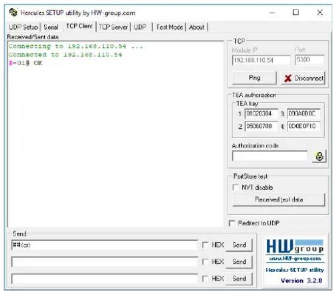
Protocol 3000 Commands
| Function | Description | Syntax | Parameters/Attributes | Example |
| # | Protocol handshaking.↑ Validates the Protocol 3000 connection and gets the machine number.Step-in master products use this command to identify the availability of a device. | COMMAND#FEEDBACK-nn@_okLF> | # | |
| AUD-EMB? | Get audio in video embedding status. | COMMAND#AUD-EMB?_in_index,out_indexFEEDBACK-nn@AUD-EMB_in_index,out_index,amb_modeLF> | in_index - Number that indicates the specific input:1-4 (or 1-2)out_index - Number that indicates the specific output:1emb_mode - Embedding status0 - Analog1 - Embedded2 - Auto | Get audio embedded status of input 1:#AUD-EMB?_1,1 |
| AUD-LVL | Set volume level. | COMMAND#AUD-LVL_io_mode,io_index,vol_levelFEEDBACK-nn@AUD-LVL_io_mode,io_index,vol_levelLF> | io_mode -1 - Outputio_index - 1vol_level - Volume level -96.0db to 12.0dB;++ (increase current value by 0.5dB);-- (decrease current value by 0.5dB) | Set AUDIO OUT level to -50.0dB:#AUD-LVL_1,1,-50.0 |
| AUD-LVL? | Get volume level. | COMMAND#AUD-LVL?_io_mode,io_indexFEEDBACK-nn@AUD-LVL_io_mode,io_index,vol_levelLF> | io_mode -1 - Outputio_index - 1vol_level - Volume level -96.0db to 12.0dB; | Get AUDIO OUT level:#AUD-LVL?_1,1 |
| AUD-LVL-RANGE? | Get volume level min and max range. | COMMAND#AUD-LVL-RANGE?_io_mode,io_indexFEEDBACK-nn@AUD-LVL-RANGE_io_mode,io_index,min_val,max_valLF> | io_mode -1 - Outputio_index - 1min_val - -96.0dbmax_val - 12.0dB | Get AUDIO OUT level range:#AUD-LVL-RANGE?_1,1 |
| AUD-ONLY? | Get audio-only mode status | COMMAND#AUD-ONLY?_io_modeFEEDBACK-nn@AUD-ONLY_io_mode,statusLF> | io_mode -1 - Outputstatus - On/Off0 - Off1 - On | Get audio-only status:#AUD-ONLY?_1 |
| AUD-SIGNAL? | Get audio input signal status. | COMMAND#AUD-SIGNAL?_in_indexFEEDBACK-nn@AUD-SIGNAL_in_index,statusLF> | in_index - Number that indicates the specific input:1-N (N= the total number of inputs)status - On/Off0 - Off (no signal)1 - On (signal present) | Get the status of input 1:#AUD-SIGNAL?_ |
| AUD-SIG-TYPE | Get audio-only mode status | COMMAND#AUD-SIG-TYPE_io_mode,io_index,signal_typeFEEDBACK-nn@AUD-SIG-TYPE_io_mode,io_index,signal_typeLF> | io_mode -0 - Input1 - Outputio_index -Number that indicates the specific input:1-N (N= the total number of inputs)signal_type - On/Off0 - AES1 - Analog2 - ARC | Set audio output signal type to ARC:#AUD-SIG-TYPE_1,7,7 |
| AUD-SIG-TYPE? | Get audio-only mode status | COMMAND#AUD-SIG-TYPE?_io_mode,io_indexFEEDBACK-nn@AUD-SIG-TYPE_io_mode,io_index,signal_typeLF> | io_mode -0 - Input1 - Outputio_index -Number that indicates the specific input:1-N (N= the total number of inputs)signal_type - On/Off0 - AES1 - Analog2 - ARC | Get audio output signal type:#AUD-SIG-TYPE?_1,1 |
| AV-SW-MODE? | Get input auto switch mode (per output). | COMMAND#AV-SW-MODE?_layer_type,out_indexFEEDBACK-nn@AV-SW-MODE_layer_type,out_index,connection_modeLF> | layer_type - Number that indicates the signal type:1 - Video2 - Audioout_index - 1connection_mode - Connection mode0 - manual1 - priority switch2 - last connected switch | Get the input audio switch mode for HDMI OUT:#AV-SW-MODE?_1,1 |
| AV-SW-TIMEOUT | Set auto switching timeout. | COMMAND#AV-SW-TIMEOUT_switching_mode,time_outFEEDBACK-nn@AV-SW-TIMEOUT_switching_mode,time_outLF> | switching_mode - Switching mode0 - Video signal lost4 - Disable 5V on video output if no input signal detected5 - Video cable unpluggedtime_out - Timeout in seconds0 - 60000 | Set the auto switching timeout to 5 seconds in the event of 5V disable when no input signal is detected:#AV-SW-TIMEOUT_1,1 |
| AV-SW-TIMEOUT? | Set auto switching timeout. | COMMAND#AV-SW-TIMEOUT?_switching_nodeFEEDBACK~nn@AV-SW-TIMEOUT_switching_mode,time_outLF> | switching_mode - Switching mode0 - Video signal lost4 - Disable 5V on video output if no input signal detected5 - Video cable unpluggedtime_out - Timeout in seconds0 - 60000 | Get the auto switching timeout to for video signal loss:#AV-SW-TIMEOUT?_0 |
| BEACON-INFO? | Get beacon information, including IP address, UDP control port, TCP control port, MAC address, model, name. | COMMAND#BEACON-INFO?FEEDBACK~nn@BEACON-INFO_port_id, ip string, udb_port, tcp_port, mac_address, model, nameLF> | port_id - ID of the Ethernet portip_string - Dot-separated representation of the IP addressudp_port - UDP control porttcp_port - TCP control portmac_address - Dash-separated mac addressmodel - Device modelname - Device name | Get beacon information:#BEACON-INFO?_ |
| BUILD-DATE? | Get device build date. | COMMAND#BUILD-DATE?FEEDBACK~nn@BUILD-DATE_date_timeLF> | date - Format: YYYY/MM/DD whereYYYY = YearMM = MonthDD = Daytime - Format: hh:mm:ss wherehh = hoursmm = minutesss = seconds | Get the device build date:#BUILD-DATE? |
| CEC-GW-PORT-ACTIVE | Set gateway port status. | COMMAND#CEC-GW-PORT-ACTIVE_port_ID,statusFEEDBACK~nn@CEC-GW-PORT-ACTIVE_port_ID,statusLF> | Port_id - 1status -0 - Off1 - On | Set the gateway port status to enable:#CEC-GW-PORT-ACTIVE_1,1 |
| CEC-GW-PORT-ACTIVE? | Get gateway port status. | COMMAND#CEC-GW-PORT-ACTIVE_port_IDFEEDBACK~nn@CEC-GW-PORT-ACTIVE_port_ID,statusLF> | Port_id - 1status -0 - Off1 - On | Get the gateway port status:#CEC-GW-PORT-ACTIVE?_ |
| CEC-LOGIC-ADDR | Set device CEC logical address. | COMMAND#CEC-LOGIC-ADDR_port_index,isFEEDBACK~nn@CEC-LOGIC-ADDR_port_index,isLF> | Port_index - 1la - 1 to 15 | Show device logic address:#CEC-LOGIC-ADDR_1,1 |
| CEC-LOGIC-ADDR? | Get device CEC logical address. | COMMAND#CEC-LOGIC-ADDR_port_indexCRFEEDBACK~nn@CEC-LOGIC-ADDR_port_index,isLF> | Port_index - 1la - 1 to 15 | Get device logic address:#CEC-LOGIC-ADDR_out.html: |
| CEC-MEMBERS? | Get list of CEC logical addresses. | COMMAND#CEC-MEMBERS_port_indexFEEDBACK~nn@CEC-MEMBERS_port_index,,<la2>..<CRLF> | Port_index - 1la - 1 to 15 | Set gateway members:#CEC-MEMBERS?_1 |
| CEC-NTFY | Notify about CEC command retrieved from bus.1 Notification is sent to all com ports upon CEC message retrieval from CEC bus | COMMAND#CEC-NTFYFEEDBACK~nn@CEC-NTFY_port_num,len,,<ce command>,<cr><LF> | port_num - 1 port notifying the commandlen - 1-16cec command - CEC format command (in HEX format, no leading zeros, no '0x' prefix) | Notify about CEC command retrieved from bus:#CEC-NTFY |
| CEC-SND | Send CEC command to port. | COMMAND#CECSND_port_index,sn_id,cmd_name,cec_len,cec commandFEEDBACK~nn@CEC-SND_port_index,sn_id,cmd_name,cec_modeLF> | port_index - CEC port transmitting the command (1 - number of ports)sn_id - serial number of command for flow control and response commands from devicecmd_name - command namecec_len - 1-16cec command - CEC format command (in HEX format, no leading zeros, no '0x' prefix)cec_mode - CEC mode0 - Sent1 - Gateway disabled2 - Inactive CEC-Master3 - Busy4 - Illegal Message Parameter5 - Illegal CEC Address Parameter6 - Illegal CEC Command7 - Timeout8 - Error | Send CEC command to port:#CECSND_1,1,1,1,1 |
| CPEDID | Copy EDID data from the output to the input EEPROM.1 Destination bitmap size depends on device properties (for 64 inputs it is a 64-bit word).Example: bitmap 0x0013 means inputs 1,2 and 5 are loaded with the new EDID.In certain products Safe mode is an optional parameter.See the HELP command for its availability. | COMMAND#CPEDID_edid_io,src_id,edid_io,dest_bitmapor#CPEDID_edid_io,src_id,edid_io,dest_bitmap,safe_modeFEEDBACK~nn@CPEDID_edid_io,src_id,edid_io,dest_bitmap(LF)~nn@CPEDID_edid_io,src_id,edid_io,dest_bitmap,safe_mode(LF) | edid_io-EDID source type (usually output)0 - Input1 - Output2 - Default EDID3 - Custom EDIDsrc_id-Number of chosen source stage0 - Default EDID sourceFor inputs0 - Input 11 - Input 22 - Input 33 - Input 4For output - 1For custom EDID -edid_io-EDID destination type (usually input)0 - Inputdest_bitmap-Bitmap representing destination IDs. Format: XXXX..X, where X is hex digit. The binary form of every hex digit represents corresponding destinations.0 - indicates that EDID data is not copied to this destination.1 - indicates that EDID data is copied to this destination.safe_node-Safe mode0 - device accepts the EDID as is without trying to adjust1 - device tries to adjust the EDID (default value if no parameter is sent) | Copy the EDID data from the Output 1 (EDID source) to the Input:#CPEDID_1,1,0,0x1<CR>Copy the EDID data from the default EDID source to the Input:#CPEDID_2,3,0,0x1<CR> |
| DISPLAY? | Get output HPD status. | COMMAND#DISPLAY?_out_indexFEEDBACK~nn@DISPLAY_out_index,status(LF) | out_index-Number that indicates the specific output:1status-HPD status according to signal validation0 - Signal or sink is not valid1 - Signal or sink is valid2 - Sink and EDID is valid | Get the output HPD status of Output 1:#DISPLAY?_1 |
| DPSW-STATUS? | Get the DIP-switch state. | COMMAND#DPSW-STATUS?_sip_idFEEDBACK~nn@DPSW-STATUS_dip_id,status(LF) | dip_id-1 to 4 (number of DIP switches)status-Up/down0 - Up1 - Down | Get the DIP-switch 2 status:#DPSW-STATUS?_2 |
| EDID-DC | Force removal of deep color on EDID or leaving it as in the original EDID. | COMMAND#EDID-DC_in_index,deep_color_stateFEEDBACK~nn@EDID-DC_in_index,deep_color_state(LF) | in_index-Number that indicates the specific input:1 - Input 12 - Input 23 - Input 34 - Input 4deep_color_state-0 - Don't change1 - Remove deep color | Remove deep color on EDID for input 1.#EDID-DC_1,1 |
| EDID-DC? | Get deep color status on EDID. | COMMAND#EDID-DC?_in_indexFEEDBACK~nn@EDID-DC_in_index,deep_color_state(LF) | in_index-Number that indicates the specific input:0 - Input 11 - Input 22 - Input 33 - Input 4deep_color_state-0 - Don't change1 - Remove deep color | Get deep color state on EDID for input 2.#EDID-DC?_2 |
| ETH-PORT | Set Ethernet port protocol.1 If the port number you enter is already in use, an error is returned.The port number must be within the following range: 0-(2*16-1). | COMMAND#ETH-PORT_port_type,port_idFEEDBACK~nn@ETH-PORT_port_type,port_id(LF) | port_type-TCP/UDP port_id-TCP/UDP port number (0 - 65535) | Set the Ethernet port protocol for TCP to 12457:#ETH-PORT_TCP,12437 |
| ETH-PORT? | Get Ethernet port protocol.1 If the port number you enter is already in use, an error is returned.The port number must be within the following range: 0-(2*16-1). | COMMAND#ETH-PORT?_port_typeFEEDBACK~nn@ETH-PORT_port_type,port_id(LF) | port_type-TCP/UDP port_id-TCP/UDP port number (0 - 65535) | Get the Ethernet port protocol for UDP:#ETH-PORT?_UDP<CR> |
| FACTORY | Reset device to factory default configuration.1 This command deletes all user data from the device. The deletion can take some time.Your device may require powering off and powering on for the changes to take effect. | COMMAND#FACTORYFEEDBACK~nn@FACTORY_ok | Reset the device to factory default configuration:#FACTORY | |
| GEDID | Get EDID support on certain input/output using an external application1 For old devices that do not support this command.~nn@ERR002LF>is received. | COMMAND#GEDID_io_node,in_indexFEEDBACK~nn@GEDID_io_mode,in_index,sizeLF> | io_mode- Input/Output0- Input1 - Output2 - Default EDID3 - Custom EDIDin_index- Number that indicates the specific input:1-N (N= the total number of inputs)size - Size of data to be sent from device, 0 means no EDID support | Get EDID support information for input 1:#GEDID_11 |
| HDCP-MOD | Set HDCP mode.1 Set HDCP working mode on the device input:HDCP supported - HDCP_ON [default].HDCP not supported - HDCP OFF.HDCP support changes following detected sink - MIRROR OUTPUT.When you define 3 as the mode, the HDCP status is defined according to the connected output in the following priority: OUT 1,OUT 2. If the connected display on OUT 2 supports HDCP, but OUT 1 does not, then HDCP is defined as not supported. If OUT 1 is not connected, then HDCP is defined by OUT 2. | COMMAND#HDCP-MOD_in_index,modeFEEDBACK~nn@HDCP-MOD_in_index,modeLF> | in_index- Number that indicates the specific input:1-N (N= the total number of inputs)mode- HDCP mode:0- HDCP Off3- HDCP defined according to the connected output | Set the input HDCP-MODE of IN 1 to Off:#HDCP-MOD_1,0 |
| HDCP-MOD? | Set HDCP mode.1 Set HDCP working mode on the device input:HDCP supported - HDCP_ON [default].HDCP not supported - HDCP OFF.HDCP support changes following detected sink - MIRROR OUTPUT.When you define 3 as the mode, the HDCP status is defined according to the connected output in the following priority: OUT 1,OUT 2. If the connected display on OUT 2 supports HDCP, but OUT 1 does not. then HDCP is defined as not supported. If OUT 1 is not connected, then HDCP is defined by OUT 2. | COMMAND#HDCP-MOD?_in_indexFEEDBACK~nn@HDCP-MOD_in_index,modeLF> | in_index- Number that indicates the specific input:0- Input 11- Input 22- Input 33- Input 4mode- HDCP mode:0- HDCP Off3- HDCP defined according to the connected output | Get the input HDCP-MODE of IN 2:#HDCP-MOD?_2 |
| HDCP-OUT | Set HDCP output mode. | COMMAND#HDCP-OUT_out_index,modeFEEDBACK~nn@HDCP-OUT_out_index,modeLF> | out_index- 1mode- HDCP mode:0- Follow input1-Always on | Set the output HDCP-MODE to Follow Input:#HDCP-MOD_1,0 |
| HDCP-OUT? | Get HDCP output mode. | COMMAND#HDCP-OUT?,out_indexFEEDBACK~nn@HDCP-OUT, out_index, modeLF> | out_index - 1mode - HDCP mode:0 - Follow input1 -Always on | Get the output HDCP-MODE:#HDCP-MOD?,1 |
| HDCP-STAT? | Get HDCP signal status.i_io_mode =1 - get the HDCP signal status of the sink device connected to the specified output.io_mode =0 - get the HDCP signal status of the source device connected to the specified input. | COMMAND#HDCP-STAT?,io_mode,in_indexFEEDBACK~nn@HDCP-STAT,io_mode,in_index,statusLF> | io_mode - Input/Output0 - Input1 - Outputio_index - Number that indicates the specific number of inputs or outputs (based on io_mode):For inputs:0 - Input 11 - Input 22 - Input 33 - Input 4For output: - 1status - Signal encryption status - valid values On/Off0 - HDCP Off1 - HDCP On or HDCP 1.42 - HDCP 2.2 | Get the output HDCP-STATUS of IN1:#HDCP-STAT?,0,1 |
| HELP | Get command list or help for specific command. | COMMAND#HELP#HELP_cmd_nareFEEDBACK1. Multi-line:~nn@Device_cmd_name,.cmd_name.LF>To get help for command use: HELP (COMMAND_NAME)LF>~nn@HELP_cmd_name:descriptionLF>USAGE:usageLF> | cmd_name - Name of a specific command | Get the command list:#HELPTo get help for AV-SW-TIMEOUT:HELP_av-sw-timeout |
| LDEDID | Write EDID data from external application to device.1 When the unit receives the LDEDID command it replies with READY and enters the special EDID packet wait mode. In this mode the unit can receive only packets and not regular protocol commands.If the unit does not receive correct packets for 30 seconds or is interrupted for more than 30 seconds before receiving all packets, it sends timeout error~nn@LDEDID_err01LF> and returns to the regular protocol mode. If the unit received data that is not a correct packet, it sends the corresponding error and returns to the regular protocol mode. | COMMANDMulti-step syntaxFEEDBACKStep 1:#LDEDID_edid_io,dest bitmask,edid_size,safe modeResponse 1:~nn@LDEDID_edid_io,dest bitmask,edid_size,safe_mode_readyor~nn@LDEDID_errno<CRLF>Step 2: If ready was received, send EDID_DATAResponse 2:~nn@LDEDID_edid_io,dest bitmask,edid_size,safe_mode_okLF>or~nn@LDEDID_errno<CRLF> | edid_io - EDID destination type (usually input)0 - Input1 - Output2 - Default EDID3 - Custom EDIDdest bitmask - Bitmap representing destination IDs. Format: 0x******, where * is ASCII presentation of hex digit. The binary presentation of this number is a bit mask for destinations. Setting '1' means EDID data has to be copied 'to this destinationedid_size - EDID data sizesafe_mode - Safe mode0 - Device accepts the EDID as is without trying to adjust1 - Device tries to adjust the EDIDedid_data - Data in protocol packets Using The Packet Protocol Send a command: LDRV, LOAD, IROUT, LDEDIDReceive Ready or ERR##If Ready:a. Send a packet,b. Receive OK on the last packet,c. Receive OK for the command Packet structure:Packet ID (1, 2, 3...) (2 bytes in length)Length (data length + 2 for CRC) -(2 bytes in length)Data (data length - 2 bytes)CRC - 2 bytesU1 U2 U3 U4 U5Packet ID Length Data CRC5. Response: ~nnnn_okLF>(Where N/NNN is the received packet ID in ASCII hex digits.) | Write the EDID data from an external application to the HDMI In 1 Input without adjustment attempts:#LDEDID_0,0x1,2340,0Write the EDID data from an external application to HDMI In 1 and PC In inputs with adjustment attempts:#LDEDID_0,0x5,2340,1 |
| LOCK-EDID | Lock last read EDID. | COMMAND#LOCK-EDID_in_index,lock_modeFEEDBACK~nn@LOCK-EDID_in_index,lock_modeLF> | in_index - Number that indicates the specific input:1 - Input 12 - Input 23 - Input 34 - Input 4lock_mode - On/Off0 - Off unlocks EDID1 - On locks EDID | Lock the last read EDID from input 2:#LOCK-EDID_2,1 |
| LOCK-EDID? | Get EDID Lock status. | COMMAND#LOCK-EDID?,in_indexFEEDBACK~nn@LOCK-EDID_in_index,lock_modeLF> | in_index - Number that indicates the specific input:1 - Input 12 - Input 23 - Input 34 - Input 4lock_mode - On/Off0 - Off unlocks EDID1 - On locks EDID | Get input 2 Lock EDID status:#LOCK-EDID?,7 |
| LOGIN | Set protocol permission. i The permission system works only if security is enabled with the "SECUR" command. LOGIN allows the user to run commands with an End User or Administrator permission level. When the permission system is enabled, LOGIN enables running commands with the User or Administrator permission level When set, login must be performed upon each connection It is not mandatory to enable the permission system in order to use the device In each device, some connections allow logging in to different levels. Some do not work with security at all. Connection may logout after timeout. | COMMAND #LOGIN_login_level, passwordFEEDBACK ~nn@LOGIN_login_level, password_ok(LF) or ~nn@LOGIN_err_004(LF)(if bad password entered) | login_level – Level of permissions required (User or Admin) password – Predefined password (by PASS command). Default password is an empty string | Set the protocol permission level to Admin (when the password defined in the PASS command is 33333): #LOGIN_admin, 33333 |
| LOGIN? | Get protocol permission state. i The permission system works only if security is enabled with the "SECUR" command. LOGIN allows the user to run commands with an End User or Administrator permission level. When the permission system is enabled, LOGIN enables running commands with the User or Administrator permission level When set, login must be performed upon each connection It is not mandatory to enable the permission system in order to use the device In each device, some connections allow logging in to different levels. Some do not work with security at all.Connection may logout after timeout. | COMMAND #LOGIN_login_levelFEEDBACK ~nn@LOGIN_login_level, password_ok(LF) or ~nn@LOGIN cerr_00(LF)(if bad password entered) | login_level – Level of permissions required (User or Admin) password – Predefined password (by PASS command). Default password is an empty string or NO SECURE if authentication is removed. | Get the protocol permission level to Admin: #LOGIN?_admin |
| LOGOUT | Cancel current permission level. i Logs out from End User or Administrator permission levels to Not Secure. | COMMAND #LOGOUTFEEDBACK ~nn@LOGOUT_ok(LF) | #LOGOUT | |
| MODEL? | Get device model.1 This command identifies equipment connected to VS-211XS and notifies of identity changes to the connected equipment. The Matrix saves this data in memory to answer REMOTE-INFO requests. | COMMAND#MODEL?FEEDBACK~nn@MODEL_model_rane | model_name - String of up to 19 printable ASCII chars | Get the device model:#MODEL?_ |
| MUTE | Set audio mute. | COMMAND#MUTE_out_index,mute_modeFEEDBACK~nn@MUTE_out_index,mute_mode | out_index -1mute_mode - On/Off0 - Off1 - On | Set Output 1 to mute:#MUTE_1,1 |
| MUTE? | Set audio mute. | COMMAND#MUTE_out_indexFEEDBACK~nn@MUTE_out_index,mute_mode | out_index -1mute_mode - On/Off0 - Off1 - On | Get Output 1 to mute:#MUTE_1,1 |
| NAME | Set machine (DNS) name.1 The machine name is not the same as the model name. The machine name is used to identify a specific machine or a network in use (with DNS feature on). | COMMAND#NAME_machine_nameFEEDBACK~nn@NAME_machine_name | machine_name - String of up to 15 alpha-numeric chars (can include hyphen, not at the beginning or end) | Set the DNS name of the device to room-442:#NAME_room-442 |
| NAME? | Get machine (DNS) name.1 The machine name is not the same as the model name. The machine name is used to identify a specific machine or a network in use (with DNS feature on). | COMMAND#NAME?FEEDBACK~nn@NAME_machine_name | machine_name - String of up to 15 alpha-numeric chars (can include hyphen, not at the beginning or end) | Get the DNS name of the device:#NAME?_ |
| NAME-RST | Reset machine (DNS) name to factory default.1 Factory default of machine (DNS) name is "KRAMER_" + 4 last digits of device serial number. | COMMAND#NAME-RSTFEEDBACK~nn@NAME-RST_ok | Reset the machine name ($/N last digits are 0102):#NAME-RST_kramer_0102 | |
| NET-CONFIG | Set a network configuration.1 Parameters [DNS1] and [DNS2] are optional.1 For Backward compatibility, the id parameter can be omitted. In this case, the Network ID, by default, is 0, which is the Ethernet control port.1 If the gateway address is not compliant to the subnet mask used for the host IP, the command will return an error. Subnet and gateway compliance specified by RFC950. | COMMAND#NET-CONFIG_netw_id,net_ip,net_mask,gateway,[dns1],[dns2]FEEDBACK~nn@NET-CONFIG_netw_id,net_ip,net_mask,gateway | netw_id - 0net_ip - Network IPnet_mask - Network maskgateway - Network gateway | Set the device network parameters to IP address 192.168.113.10, net mask 255.255.0.0, and gateway 192.168.0.1:#NET-CONFIG_5,192.169.1.3.10,255.255.0.0,.92.168.0.1 |
| NET-CONFIG? | Get a network configuration.1 Parameters [DNS1] and [DNS2] are optional.1 For Backward compatibility, the id parameter can be omitted. In this case, the Network ID, by default, is 0, which is the Ethernet control port.1 If the gateway address is not compliant to the subnet mask used for the host IP, the command will return an error. Subnet and gateway compliancy specified by RFC950. | COMMAND#NET-CONFIG_netw_id,net_ip,net_mask,gateway,[dns1],idn2)<CR>FEEDBACK~nn@NET-CONFIG_netw_id,net_ip,net_mask,gateway<CR><IF> | netw_id - 0net_ip - Network IPnet_mask - Network maskgateway - Network gateway | Get the device network parameters: #NET-CONFIG?_<CR> |
| NET-DHCP | Set DHCP mode.1 Only 1 is relevant for the mode value. To disable DHCP, the user must configure a static IP address for the device. Connecting Ethernet to devices with DHCP may take more time in some networks.To connect with a randomly assigned IP by DHCP, specify the device DNS name (if available) using the NAME command. You can also get an assigned IP by direct connection to USB or RS-232 protocol port, if available.For proper settings consult your network administrator.1 For Backward compatibility, the id parameter can be omitted. In this case, the Network ID, by default, is 0, which is the Ethernet control port. | COMMAND#NET-DHCP_netw_id,dhcp_state<CR>FEEDBACK~nn@NET-DHCP_netw_id,dhcp_state<CR><LF> | netw_id - Network ID-the device network interface (if there are more than one). Counting is 0 based, meaning the control port is '0', additional ports are 1,2,3\dhcp_state - 0 - Do not use DHCP. Use the IP set by the factory or using the net-ip or net-config command.1 - Try to use DHCP. If unavailable, use the IP set by the factory or using the net-ip or net-config command. | Enable DHCP mode for port 1, if available: #NET-DHCP_1, |
| NET-DHCP? | Get DHCP mode.1 For Backward compatibility, the id parameter can be omitted. In this case, the Network ID, by default, is 0, which is the Ethernet control port. | COMMAND#NET-DHCP?_netx_id<CR>FEEDBACK~nn@NET-DHCP_netw_id,dhcp_state<CR><LF> | netw_id - Network ID-the device network interface (if there are more than one). Counting is 0 based, meaning the control port is '0', additional ports are 1,2,3\dhcp_state - 0 - Do not use DHCP. Use the IP set by the factory or using the net-ip or net-config command.1 - Try too use DHCP. If unavailable, use the IP set by the factory or using the net-ip or net-config command. | Get DHCP mode for port 1: #NET-DHCP?_1<CR> |
| NET-GATE | Set gateway IP.1 A network gateway connects the device via another network and maybe over the Internet. Be careful of security issues. For proper settings consult your network administrator. | COMMAND#NET-GATE_ip_address<CR>FEEDBACK~nn@NET-GATE_ip_address<CR><LF> | ip_address - Format: xxx.xxx.xxx.xxx | Set the gateway IP address to 192.168.0.1: #NET-GATE_192.168.000.00 |
| NET-GATE? | Get gateway IP.1 A network gateway connects the device via another network and maybe over the Internet. Be aware of security problems. | COMMAND#NET-GATE?_<CR>FEEDBACK~nn@NET-GATE_ip_address<CR><LF> | ip_address - Format: xxx.xxx.xxx.xxx | Get the gateway IP address: #NET-GATE?_<CR> |
| NET-IP | Set IP address.1 For proper settings consult your network administrator. | COMMAND#NET-IP_ip_addressFEEDBACK~nn@NET-IP_ip_addressLF> | ip_address - Format: xxx.xxx.xxx.xx | Set the IP address to 192.168.1.39:#NET-IP_192.168.001.039 |
| NET-IP? | Get IP address. | COMMAND#NET-IP?FEEDBACK~nn@NET-IP_ip_addressLF> | ip_address - Format: xxx.xxx.xxx.xx | Get the IP address:#NET-IP? |
| NET-MAC? | Get MAC address.1 For backward compatibility, the id parameter can be omitted. In this case, the Network ID, by default, is 0, which is the Ethernet control port. | COMMAND#NET-MAC?idFEEDBACK~nn@NET-MAC_id,mac_addressLF> | id - Network ID - the device network interface (if there are more than one). Counting is 0 based, meaning the control port is '0', additional ports are 1,2,3,... mac_address - Unique MAC address. Format: XX-XX-XX-XX-XX where X is hex digit | #NET-MAC?id |
| NET-MASK | Set subnet mask.1 For proper settings consult your network administrator. | COMMAND#NET-MASK_net_masFEEDBACK~nn@NET-MASK_net_masLF> | net_mask - Format: xxx.xxx.xxx.xx | Set the subnet mask to 255.255.0: #NET-MASK_255.255.000.000 |
| NET-MASK? | Get subnet mask. | COMMAND#NET-MASK?FEEDBACK~nn@NET-MASK_net[maskLF> | net_mask - Format: xxx.xxx.xxx.xx | Get the subnet mask:#NET-MASK? |
| PASS | Set password for login level.The default password is an empty string. | COMMAND#PASS_login_level,passwordFEEDBACK~nn@PASS_login_level,passwordLF> | login_level - Level of login to set (End User or Administrator). password - Password for the login level. Up to 15 printable ASCII chars | Set the password for the Admin protocol permission level to 33333:#PASS_admin_23333 |
| PASS? | Get password for login level.The default password is an empty string. | COMMAND#PASS_login_levelFEEDBACK~nn@PASS_login_level,passwordLF> | login_level - Level of login to set (End User or Administrator). password - Password for the login level. Up to 15 printable ASCII chars | Get the password for the Admin protocol permission:#PASS?_admin |
| PRIORITY | Set input priority.WP-577VH-layer parameter is not used. | COMMAND#PRIORITY_layer_type,priority_1,priority_2,priority_4FEEDBACK~nn@PRIORITY_layer_type,priority_1,priority_2,priority_4CRLF> | layer_type - Layer Enumeration 1 - Video priority - Priority of inputs (1-4) | Set the video input priority with input 2 as the highest priority:#PRIORITY_1,2,3,1,4 |
| PRIORITY? | Set input priority. | COMMAND#PRIORITY?layer_typeFEEDBACK~nn@PRIORITY_layer_type,priority_1,priority_2,priority_4CRLF> | layer_type - Layer Enumeration 1 - Video priority - Priority of inputs (1-4) | Set the video input priority with input 2 as the highest priority:#PRIORITY?_1 |
| PROG-BTN-MOD | Set programmable buttons mode. | COMMAND#PROG-BUTTON-MOD_modeFEEDBACK~nn@PROG-BUTTON-MOD_modeLF> | mode-0 - Default behavior 1 - Programmable | Set the buttons to programmable mode:#PROC-BTN-MOD_1 |
| PROG-BTN-MOD? | Set programmable buttons mode. | COMMAND#PROG-BUTTON-MOD?FEEDBACK~nn@PROG-BUTTON-MOD_modeLF> | mode-0 - Default behavior 1 - Programmable | Get the buttons to programmable mode:#PROC-BTN-MOD? |
| PROT-VER? | Get device protocol version. | COMMAND#PROT-VER?FEEDBACK~nn@PROT-VER_300C:versionLF> | version - XX.XX where X is a decimal digit | Get the device protocol version:#PROT-VER? |
| RESET | Reset device.To avoid locking the port due to a USB bug in Windows, disconnect USB connections immediately after running this command. If the port was locked, disconnect and reconnect the cable to reopen the port. | COMMAND#RESETFEEDBACK~nn@RESET_cLF> | Reset the device:#RESET | |
| ROUTE | Set layer routing.This command replaces all other routing commands. | COMMAND#ROUTE_layer_type,out_index,in_indexFEEDBACK~nn@ROUTE_layer_type,out_index,in_indexLF> | layer_type Layer Enumeration 1 - Video out_index 1 - Output in_index - Source id 1 - Input 1 2 - Input 2 3 - Input 3 4 - Input 4 | Route video input 2 to the output:#ROUTE_1,1,2 |
| ROUTE? | Get layer routing state.1 This command replaces all other routing commands. | COMMAND#ROUTE?_layer_type,out_indexFEEDBACK~nn@ROUTE_layer_type,out_index,in_indexLF> | layer_type Layer Enumeration1 - Videoout_index1 - OUT 1 HDMIin_index - Source id1 - Input 12 - Input 23 - Input 34 - Input 4 | Get video routing output:#ROUTE?_1,1 |
| SECUR | Start/stop security.1 The permission system works only if security is enabled with the "SECUR" command. | COMMAND#SECUR_security_stateFEEDBACK~nn@SECUR_security_stateLF> | security_state - Security state0 - OFF (disables security)1- ON (enables security) | Enable the permission system:#SECUR_1 |
| SECUR? | Get security state.1 The permission system works only if security is enabled with the "SECUR" command. | COMMAND#SECUR?_security_stateFEEDBACK~nn@SECUR_security_stateLF> | security_state - Security state0 - OFF (disables security)1- ON (enables security) | Enable the permission system:#SECUR?_ |
| SIGNAL? | Get input signal status. | COMMAND#SIGNAL?_in_indexFEEDBACK~nn@SIGNAL_in_index,statusLF> | in_index - Number that indicates the specific input:1-N (N= the total number of inputs)status - Signal status according to signal validation:0 - Off1 - On | Get the input signal lock status of IN 1:#SIGNAL?_1 |
| SN? | Get device serial number. | COMMAND#SN?FEEDBACK~nn@SN_serial_numLF> | serial_num - 14 decimal digits, factory assigned | Get the device serial number:#SN?_ |
| TIME | Set device time and date.1 The year must be 4 digits.The device does not validate the day of week from the date.Time format - 24 hours.Date format - Day, Month, Year. | COMMAND#TIME_day_of_week,date,dataFEEDBACK~nn@TIME_day_of_week,date,dataLF> | day_of_week - One of {SUN,MON,TUE,WED,THU,FRI,SAT}date - Format: DD-MM-YYYY.data - Format: hh:mm:ss wherehh = hoursss = seconds | Set device time and date to December 5.2018 at 2:30pm:#TIME_mon_05-12-2018,14:30:00 |
| TIME? | Get device time and date.1 The year must be 4 digits.The device does not validate the day of week from the date.Time format - 24 hours.Date format - Day, Month, Year. | COMMAND#TIME?FEEDBACK~nn@TIME_day_of_week,date,dataLF> | day_of_week - One of {SUN,MON,TUE,WED,THU,FRI,SAT}date - Format: YYYY/MM/DD whereYYYY = YearMM = MonthDD = Daydata - Format: hh:mm:ss wherehh = hoursss = seconds | Get device time and date:#TIME? |
| TIME-LOC | Set local time offset from UTC/GMT.1 If the time server is configured, device time calculates by adding UTC_off to UTC time (that it got from the time server)+ 1 hour if daylight savings time is in effect.TIME command sets the device time without considering these settings. | COMMAND#TIME-LOC_utc_off,dst_stateFEEDBACK~nn@TIME-LOC_utc_off,dst_stateLF> | utc_off - Offset of device time from UTC/GMT (without daylight time correction)dst_state - Daylight saving time state0 - no daylight saving time1 - daylight saving time | Set local time offset to 3 with no daylight-saving time:#TIME-LOC_3,0 |
| TIME-LOC? | Get local time offset from UTC/GMT.1 If the time server is configured, device time calculates by adding UTC_off to UTC time (that it got from the time server)+ 1 hour if daylight savings time is in effect.TIME command sets the device time without considering these settings. | COMMAND#TIME-LOC?FEEDBACK~nn@TIME-LOC_utc_off,dst_stateLF> | utc_off - Offset of device time from UTC/GMT (without daylight time correction)dst_state - Daylight saving time state0 - no daylight saving time1 - daylight saving time | Get local time offset from UTC/GMT:#TIME-LOC? |
| TIME-SRV | Set time server.1 This command is needed for setting UDP timeout for the current client list. | COMMAND#TIME-SRV_mode,tire_server_ip,sync_hourFEEDBACK~nn@TIME-SRV_mode,time_server_ip,sync_hour,server_status<LF> | mode - On/Off0 - Off1 - Ontime_server_ip-Time server IP addressssync_hour-Hour in day for time server syncserver_status - On/Off | Set time server with IP address of 128.138.140.44 to ON:#TIME-SRV_1,128.138.140.44,0,1 |
| TIME-SRV? | Get time server.1 This command is needed for setting UDP timeout for the current client list. | COMMAND#TIME-SRV?_FEEDBACK~nn@TIME-SRV_mode,time_server_ip,sync_hour,server_status<LF> | mode - On/Off0 - Off1 - Ontime_server_ip-Time server IP addressssync_hour-Hour in day for time server syncserver_status - On/Off | Get time server:#TIME-SRV? |
| VERSION? | Get firmware version number. | COMMAND#VERSION?_FEEDBACK~nn@VERSION_firmware_version<CR> | firmware_version - XX.XX.XXXX where the digit groups are:major.minor.build version | Get the device firmware version number:#VERSION?_ |
| VMUTE | Set enable/disable video on output.1 Video mute parameter 2 (blank picture) is not supported. | COMMAND#VMUTE_out_index,flagFEEDBACK~nn@VMUTE_out_index,flag<CR> | out_index - Number that indicates the specific output:1-N (N= the total number of outputs)flag-Video Mute0-Video enabled1-Video disabled2-Blank picture | Disable the video output on OUT 2:#VMUTE_2,0 |
| VMUTE? | Get video on output status.1 Video mute parameter 2 (blank picture) is not supported. | COMMAND#VMUTE?_out_indexFEEDBACK~nn@VMUTE_out_index,flag<CR> | out_index - Number that indicates the specific output:1-N (N= the total number of outputs)flag-Video Mute0-Video enabled1-Video disabled2-Blank picture | Get video on output status:#VMUTE?_2 |
Result and Error Codes
Syntax
In case of an error, the device responds with an error message. The error message syntax:
- \~NN@ERR XXX
– when general error, no specific command - \~NN@CMD ERR XXX
– for specific command - NN – machine number of device, default = 01
- XXX - error code
Error Codes
| Error Name | Error Code | Description |
| P3K_NO_ERROR | 0 | No error |
| ERR_PROTOCOL_SYNTAX | 1 | Protocol syntax |
| ERR_COMMAND_NOT_AVAILABLE | 2 | Command not available |
| ERR_PARAMETER_OUT_OF_RANGE | 3 | Parameter out of range |
| ERR_UNAUTHORIZED_ACCESS | 4 | Unauthorized access |
| ERR_INTERNAL_FW_ERROR | 5 | Internal FW error |
| ERR_BUSY | 6 | Protocol busy |
| ERR_WRONG_CRC | 7 | Wrong CRC |
| ERR_TIMEDOUT | 8 | Timeout |
| ERR_RESERVED | 9 | (Reserved) |
| ERR_FW_NOT_ENOUGH_SPACE | 10 | Not enough space for data (firmware, FPGA...) |
| ERR_FS_NOT_ENOUGH_SPACE | 11 | Not enough space – file system |
| ERR_FS_FILE_NOT_EXISTS | 12 | File does not exist |
| ERR_FS_FILE_CANT_CREATED | 13 | File can't be created |
| ERR_FS_FILE_CANT_OPEN | 14 | File can't open |
| ERR_FEATURE_NOT_SUPPORTED | 15 | Feature is not supported |
| ERR_RESERVED_2 | 16 | (Reserved) |
| ERR_RESERVED_3 | 17 | (Reserved) |
| ERR_RESERVED_4 | 18 | (Reserved) |
| ERR_RESERVED_5 | 19 | (Reserved) |
| ERR_RESERVED_6 | 20 | (Reserved) |
| ERR_PACKET_CRC | 21 | Packet CRC error |
| ERR_PACKET_MISSED | 22 | Packet number isn't expected (missing packet) |
| ERR_PACKET_SIZE | 23 | Packet size is wrong |
| ERR_RESERVED_7 | 24 | (Reserved) |
| ERR_RESERVED_8 | 25 | (Reserved) |
| ERR_RESERVED_9 | 26 | (Reserved) |
| ERR_RESERVED_10 | 27 | (Reserved) |
| ERR_RESERVED_11 | 28 | (Reserved) |
| ERR_RESERVED_12 | 29 | (Reserved) |
| ERR_EDID_CORRUPTED | 30 | EDID corrupted |
| ERR_NON_LISTED | 31 | Device specific errors |
| ERR_SAME_CRC | 32 | File has the same CRC – no changed |
| ERR_WRONG_MODE | 33 | Wrong operation mode |
| ERR_NOT_CONFIGURED | 34 | Device/chip was not initialized |
The warranty obligations of Kramer Electronics Inc. ("Kramer Electronics") for this product are limited to the terms set forth below:
What is Covered
This limited warranty covers defects in materials and workmanship in this product.
What is Not Covered
This limited warranty does not cover any damage, deterioration or malfunction resulting from any alteration, modification, improper or unreasonable use or maintenance, misuse, abuse, accident, neglect, exposure to excess moisture, fire, improper packing and shipping (such claims must be presented to the carrier), lightning, power surges, or other acts of nature. This limited warranty does not cover any damage, deterioration or malfunction resulting from the installation or removal of this product from any installation, any unauthorized tampering with this product, any repairs attempted by anyone unauthorized by Kramer Electronics to make such repairs, or any other cause which does not relate directly to a defect in materials and/or workmanship of this product. This limited warranty does not cover cartons, equipment enclosures, cables or accessories used in conjunction with this product.
Without limiting any other exclusion herein, Kramer Electronics does not warrant that the product covered hereby, including, without limitation, the technology and/or integrated circuit(s) included in the product, will not become obsolete or that such items are or will remain compatible with any other product or technology with which the product may be used.
How Long this Coverage Lasts
The standard limited warranty for Kramer products is seven (7) years from the date of original purchase, with the following exceptions:
- All Kramer VIA hardware products are covered by a standard three (3) year warranty for the VIA hardware and a standard three (3) year warranty for firmware and software updates; all Kramer VIA accessories, adapters, tags, and dongles are covered by a standard one (1) year warranty.
- Kramer fiber optic cables, adapter-size fiber optic extenders, pluggable optical modules, active cables, cable retractors, ring mounted adapters, portable power chargers, Kramer speakers, and Kramer touch panels are covered by a standard one (1) year warranty. Kramer 7-inch touch panels purchased on or after April 1st, 2020 are covered by a standard two (2) year warranty.
- All Kramer Calibre products, all Kramer Minicom digital signage products, all HighSecLabs products, all streaming, and all wireless products are covered by a standard three (3) year warranty.
- All Sierra Video MultiViewers are covered by a standard five (5) year warranty.
- Sierra switchers & control panels are covered by a standard seven (7) year warranty (excluding power supplies and fans that are covered for three (3) years).
- K-Touch software is covered by a standard one (1) year warranty for software updates.
- All Kramer passive cables are covered by a lifetime warranty.
Who is Covered
Only the original purchaser of this product is covered under this limited warranty. This limited warranty is not transferable to subsequent purchasers or owners of this product.
What Kramer Electronics Will Do
Kramer Electronics will, at its sole option, provide one of the following three remedies to whatever extent it shall deem necessary to satisfy a proper claim under this limited warranty:
- Elect to repair or facilitate the repair of any defective parts within a reasonable period of time, free of any charge for the necessary parts and labor to complete the repair and restore this product to its proper operating condition. Kramer Electronics will also pay the shipping costs necessary to return this product once the repair is complete.
- Replace this product with a direct replacement or with a similar product deemed by Kramer Electronics to perform substantially the same function as the original product. If a direct or similar replacement product is supplied, the original product's end warranty date remains unchanged and is transferred to the replacement product.
- Issue a refund of the original purchase price less depreciation to be determined based on the age of the product at the time remedy is sought under this limited warranty.
What Kramer Electronics Will Not Do Under This Limited Warranty
If this product is returned to Kramer Electronics or the authorized dealer from which it was purchased or any other party authorized to repair Kramer Electronics products, this product must be insured during shipment, with the insurance and shipping charges prepaid by you. If this product is returned uninsured, you assume all risks of loss or damage during shipment. Kramer Electronics will not be responsible for any costs related to the removal or re-installation of this product from or into any installation. Kramer Electronics will not be responsible for any costs related to any setting up this product, any adjustment of user controls or any programming required for a specific installation of this product.
How to Obtain a Remedy Under This Limited Warranty
To obtain a remedy under this limited warranty, you must contact either the authorized Kramer Electronics reseller from whom you purchased this product or the Kramer Electronics office nearest you. For a list of authorized Kramer Electronics resellers and/or Kramer Electronics authorized service providers, visit our web site at www.kramerav.com or contact the Kramer Electronics office nearest you.
In order to pursue any remedy under this limited warranty, you must possess an original, dated receipt as proof of purchase from an authorized Kramer Electronics reseller. If this product is returned under this limited warranty, a return authorization number, obtained from Kramer Electronics, will be required (RMA number). You may also be directed to an authorized reseller or a person authorized by Kramer Electronics to repair the product.
If it is decided that this product should be returned directly to Kramer Electronics, this product should be properly packed, preferably in the original carton, for shipping. Cartons not bearing a return authorization number will be refused.
Limitation of Liability
THE MAXIMUM LIABILITY OF KRAMER ELECTRONICS UNDER THIS LIMITED WARRANTY SHALL NOT EXCEED THE ACTUAL PURCHASE PRICE PAID FOR THE PRODUCT. TO THE MAXIMUM EXTENT PERMITTED BY LAW, KRAMER ELECTRONICS IS NOT RESPONSIBLE FOR DIRECT, SPECIAL, INCIDENTAL OR CONSEQUENTIAL DAMAGES RESULTING FROM ANY BREACH OF WARRANTY OR CONDITION, OR UNDER ANY OTHER LEGAL THEORY. Some countries, districts or states do not allow the exclusion or limitation of relief, special, incidental, consequential or indirect damages, or the limitation of liability to specified amounts, so the above limitations or exclusions may not apply to you.
Exclusive Remedy
TO THE MAXIMUM EXTENT PERMITTED BY LAW, THIS LIMITED WARRANTY AND THE REMEDIES SET FORTH ABOVE ARE EXCLUSIVE AND IN LIEU OF ALL OTHER WARRANTIES, REMEDIES AND CONDITIONS, WHETHER ORAL OR WRITTEN, EXPRESS OR IMPLIED. TO THE MAXIMUM EXTENT PERMITTED BY LAW, KRAMER ELECTRONICS SPECIFICALLY DISCLAIMS ANY AND ALL IMPLIED WARRANTIES, INCLUDING, WITHOUT LIMITATION, WARRANTIES OF MERCHANTABILITY AND FITNESS FOR A PARTICULAR PURPOSE. IF KRAMER ELECTRONICS CANNOT LAWFULLY DISCLAIM OR EXCLUDE IMPLIED WARRANTIES UNDER APPLICABLE LAW, THEN ALL IMPLIED WARRANTIES COVERING THIS PRODUCT, INCLUDING WARRANTIES OF MERCHANTABILITY AND FITNESS FOR A PARTICULAR PURPOSE, SHALL APPLY TO THIS PRODUCT AS PROVIDED UNDER APPLICABLE LAW. IF ANY PRODUCT TO WHICH THIS LIMITED WARRANTY APPLIES IS A "CONSUMER PRODUCT" UNDER THE MAGNUSON-MOSS WARRANTY ACT (15 U.S.C.A. §2301, ET SEQ.) OR OTHER APPLICABLE LAW, THE FOREGOING DISCLAIMER OF IMPLIED WARRANTIES SHALL NOT APPLY TO YOU, AND ALL IMPLIED WARRANTIES ON THIS PRODUCT, INCLUDING WARRANTIES OF MERCHANTABILITY AND FITNESS FOR THE PARTICULAR PURPOSE, SHALL APPLY AS PROVIDED UNDER APPLICABLE LAW.
Other Conditions
This limited warranty gives you specific legal rights, and you may have other rights which vary from country to country or state to state. This limited warranty is void if (i) the label bearing the serial number of this product has been removed or defaced, (ii) the product is not distributed by Kramer Electronics or (iii) this product is not purchased from an authorized Kramer Electronics reseller. If you are unsure whether a reseller is an authorized Kramer Electronics reseller, visit our web site at www.kramerav.com or contact a Kramer Electronics office from the list at the end of this document. Your rights under this limited warranty are not diminished if you do not complete and return the product registration form or complete and submit the online product registration form. Kramer Electronics thanks you for purchasing a Kramer Electronics product. We hope it will give you years of satisfaction.



P/N:

Rev:

SAFETY WARNING
Disconnect the unit from the power supply before opening and servicing
For the latest information on our products and a lisat of Kramer distributors, visit our website where updates to this user manual may be found.
We welcome your questions, comments, and feedback.
The terms HDMI, HDMI High-Definition Multimedia Interface, and the HDMI Logo are trademarks or registered trademarks of HDMI Licensing Administrator, Inc. All brand names, product names, and trademarks are the property of their respective owners.
- Defining VS-211XS and VS-411XS 5
- Mounting VS-211XS / VS-411XS 7
- Connecting VS-411XS 8
- Principles of Operation 10
- Operating and Controlling VS-411XS 15
- Using Embedded Web Pages 22
- Firmware Upgrade 60
- Technical Specifications 61
- Protocol 3000 69
- Introduction
- Getting Started
- Achieving Best Performance
- Safety Instructions
- Caution:
- Warning:
- Recycling Kramer Products
- Overview
- Exceptional Quality
- Advanced and User-friendly Operation
- Flexible Connectivity
- Typical Applications
- Controlling your VS-411XS
- Defining VS-211XS and VS-411XS
- Mounting VS-211XS / VS-411XS
- Connecting VS-411XS
- To connect VS-411XS as illustrated in the example in Figure 5:
- Connecting Output to a Balanced/Unbalanced Stereo Audio Acceptor
- Connecting to VS-411XS via RS-232
- Principles of Operation
- Input Auto-Switching
- IP-Driven CEC Signals Routing via Built-in Control Gateway
- Maestro Built-in Control and Automation Configuration
- Maestro Kramer Aware Touch Panel Control
- Operating and Controlling VS-411XS
- Using Front Panel Buttons
- Setting DIP-Switches
- Using Contact Closure Remote Control Pins
- Acquiring and Discovering Plug-and-Play IP Address
- Discovering IP Address
- Discovering IP Address by Performing Factory Reset
- To discover the IP address via factory reset:
- Discovering IP Address Router:
- To discover the IP address via router:
- Discovering IP Address via RS-232
- To discover the IP address via RS-232:
- Operating via Ethernet
- Connecting Ethernet Port Directly to a PC
- Connecting Ethernet Port via a Network Hub or Switch
- Configuring Ethernet Port
- Using Embedded Web Pages
- To use the browser:
- Selecting an Input
- To select an input:
- Adjusting Audio Output Volume
- Viewing and Adjusting General Settings
- Setting Remote Buttons
- To define the REMOTE contact closure buttons:
- Loading and Saving Settings
- Saving Configurations
- To save a configuration:
- Loading Configurations
- To load a configuration:
- Resetting Device
- To reset the device to its factory default parameters:
- Defining IP Settings
- Disabling DHCP
- To Disable DHCP:
- Device Settings
- IP Settings
- CEC Settings
- Enabling DHCP
- To enable DHCP
- Changing TCP/UDP Port Numbers
- To change the port numbers:
- Define CEC Gateway Settings
- To disable CEC gateway feature:
- Setting Time and Date
- To sync device time and date to a server:
- Upgrading the Firmware
- To upgrade the firmware:
- Setting Security
- To disable security:
- To enable security:
- Setting Auto Switching Priorities
- To change switching priorities:
- Setting Input Color Depth
- To Set the Color Depth on an input:
- Setting Output Audio Source for De-embedded Audio
- Audio
- Setting HDCP Support
- To set input HDCP support:
- To set output HDCP support:
- Setting Video Signal Timeouts
- Click Set Timeout.
- To set display auto-sleep entry no AV signal is detected:
- Managing EDID
- To copy an EDID from an output / input to an input:
- EDID Management
- To read the EDID from the default EDID:
- Click COPY.
- To import a customized EDID file:
- Configuring Device Control and Automation
- Configuring Ports
- Configuring Actions
- Configuring Scripts
- Maestro
- Configuring Triggers
- Operating via Maestro Kramer Aware Touch Panel
- Viewing and Executing Actions Via Maestro Control Panel
- Configuring Device Control Panel
- Selecting Panel Model
- To select the panel model:
- Setting Panel Background
- To configure the panel background:
- Defining Panel Configuration Grid
- To define the grid:
- Modifying a Button
- To modify a button:
- Click Save Changes.
- Modifying Text
- To modify the text:
- The Properties (Text Field) and NewTextField Object list appear:
- Modifying a Frame
- To modify a frame:
- Adding a New Button
- To add a new button:
- Adding a New Text Field
- To add a new text field:
- Adding a New Frame
- To add a new frame:
- Viewing About Page
- WEB VERSION 3.0.78
- Firmware Upgrade
- Default Automation settings
- Default EDID
- Protocol 3000
- Understanding Protocol 3000
- Result and Error Codes
- Syntax
- What is Covered
- What is Not Covered
- How Long this Coverage Lasts
- Who is Covered
- What Kramer Electronics Will Do
- What Kramer Electronics Will Not Do Under This Limited Warranty
- How to Obtain a Remedy Under This Limited Warranty
- Limitation of Liability
- Exclusive Remedy
- Other Conditions
Brand : Kramer
Model : VS-211XS
Category : Network switch