VS-81H - Network switch Kramer - Free user manual and instructions
Find the device manual for free VS-81H Kramer in PDF.


| Product Type | 8x1 HDMI Switcher |
| Brand | Kramer |
| Model | VS-81H |
| Dimensions (W x D x H) | 19" x 7" x 1U (483 mm x 178 mm x 44 mm) |
| Weight | Approx. 2.5 kg (5.5 lbs) |
| Power Supply | 100-240V AC, 50/60Hz, 12VA |
| Max Data Rate | 6.75 Gbps (2.25 Gbps per channel) |
| HDMI Compliance | HDMI and HDCP supported, Deep Color, x.v.Color, up to 7.1 audio |
| Maximum Resolution | Up to UXGA at 60Hz, 1080p, Deep Color |
| Inputs | 8 x HDMI |
| Output | 1 x HDMI |
| Control Methods | Front panel buttons, IR remote, RS-232, Ethernet |
| Operating Temperature | 0° to +40°C (32° to 104°F) |
| Storage Temperature | -40° to +70°C (-40° to 158°F) |
| Humidity | 10% to 90%, RHL non-condensing |
| Rack Mountable | Yes, 1U, included rack ears |
| EDID Handling | EDID pass-through, acquire from output or use default |
| PC/DVD Modes | Per-input selectable PC mode (EDID always available) or DVD mode (EDID only when switched) |
| Accessories Included | Power cord, rack ears, rubber feet, IR remote with batteries, quick start sheet, control software |
| Safety | No user-serviceable parts; use only supplied power cord; disconnect before servicing |
| Maintenance | Keep away from moisture, dust, and excessive sunlight; use high-quality cables |
Frequently Asked Questions - VS-81H Kramer
User questions about VS-81H Kramer
0 question about this device. Answer the ones you know or ask your own.
Ask a new question about this device
Download the instructions for your Network switch in PDF format for free! Find your manual VS-81H - Kramer and take your electronic device back in hand. On this page are published all the documents necessary for the use of your device. VS-81H by Kramer.
USER MANUAL VS-81H Kramer
This guide helps you install and use your product for the first time. For more detailed information, go to http://www.kramerav.com/manual/VS-81H to download the latest manual or scan the QR code on the left.
Step 1: Check what's in the box

VS-81H
8x1 HDMI Switcher
1 Power cord
1 Set of rack "ears"
4 Rubber feet
1 Quick Start sheet

Windows®-based Kramer control software Windows®-based Ethernet Configuration Manager and Virtual Serial Port Manager Infrared Remote Control Transmitter with batteries
natural_image
Illustration of a cardboard box with a small logo on the front face (no text or symbols)Save the original box and packaging in case your VS-81H needs to be returned to the factory for service.
Step 2: Install the VS-81H
Mount the machine in a rack or attach the rubber feet and place on a table.
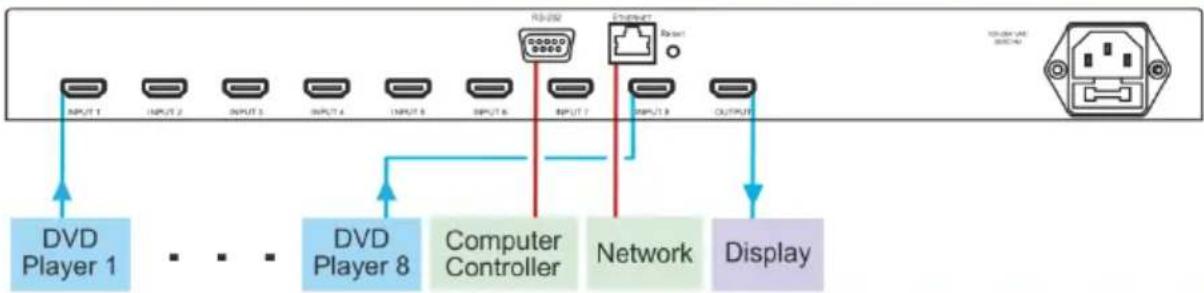
Step 3: Connect the inputs and outputs
Always switch off the power on each device before connecting it to your VS-81H.
flowchart
graph LR
    A["Input 1"] --> B["DVD Player 1"]
    C["Input 2"] --> D["DVD Player 2"]
    E["Input 3"] --> F["DVD Player 3"]
    G["Input 4"] --> H["DVD Player 4"]
    I["Input 5"] --> J["DVD Player 5"]
    K["Input 6"] --> L["DVD Player 6"]
    M["Input 7"] --> N["DVD Player 7"]
    O["Input 8"] --> P["DVD Player 8"]
    Q["Input 9"] --> R["DVD Player 9"]
    S["Output"] --> T["Display"]
    U["Computer Controller"] --> V["Network"]
    W["Controller"] --> X["Network"]
    Y["Controller"] --> Z["Network"]
Always use Kramer high-performance cables for connecting AV equipment to the VS-81H.
Step 4: Connect the power
Connect the power cord to the VS-81H and plug it into the mains electricity.

Step 5: Operate the VS-81H
Select the input, capture the EDID or lock the front panel buttons. Operate the machine from the front panel, IR remote control, RS-232 or over a network.

Contents
1 Introduction 1
2 Getting Started 2
2.1 Achieving the Best Performance 2
2.2 Safety Instructions 3
2.3 Recycling Kramer Products 3
3 Overview 4
3.1 Defining the VS-81H 8x1 HDMI Switcher 4
4 Installing in a Rack 7
5 Connecting the VS-81H 8
6 Operating the VS-81H 10
6.1 The PC and DVD Modes 10
6.2 Acquiring the EDID 11
6.3 Connecting via the RS-232 Port 12
6.4 Connecting via the ETHERNET Port 12
7 Technical Specifications 15
8 Default Communication Parameters 16
9 Protocol 2000 17
Figures
Figure 1: VS-81H 8x1 HDMI Switcher Front Panel 5
Figure 2: VS-81H 8x1 HDMI Switcher Rear Panel 6
Figure 3: Connecting the VS-81H 8x1 HDMI Switcher 9
Figure 4: Local Area Connection Properties Window 13
Figure 5: Internet Protocol (TCP/IP) Properties Window 14
1 Introduction
Welcome to Kramer Electronics! Since 1981, Kramer Electronics has been providing a world of unique, creative, and affordable solutions to the vast range of problems that confront the video, audio, presentation, and broadcasting professional on a daily basis. In recent years, we have redesigned and upgraded most of our line, making the best even better!
Our 1,000-plus different models now appear in 14 groups that are clearly defined by function: GROUP 1: Distribution Amplifiers; GROUP 2: Switchers and Routers; GROUP 3: Control Systems; GROUP 4: Format/Standards Converters; GROUP 5: Range Extenders and Repeaters; GROUP 6: Specialty AV Products; GROUP 7: Scan Converters and Scalers; GROUP 8: Cables and Connectors; GROUP 9: Room Connectivity; GROUP 10: Accessories and Rack Adapters; GROUP 11: Sierra Video Products; GROUP 12: Digital Signage; GROUP 13: Audio; and GROUP 14: Collaboration.
Congratulations on purchasing your Kramer VS-81H 8x1 HDMI Switcher, which is ideal for the following typical applications:
• Conference room presentations
- Rental and staging
2 Getting Started
We recommend that you:
- Unpack the equipment carefully and save the original box and packaging materials for possible future shipment
• Review the contents of this user manual

Go to http://www.kramerelectronics.com/support/product_downloads.asp to check for up-to-date user manuals, application programs, and to check if firmware upgrades are available (where appropriate).
2.1 Achieving the Best Performance
To achieve the best performance:
- Use only good quality connection cables (we recommend Kramer high-performance, high-resolution cables) to avoid interference, deterioration in signal quality due to poor matching, and elevated noise levels (often associated with low quality cables)
- Do not secure the cables in tight bundles or roll the slack into tight coils
- Avoid interference from neighboring electrical appliances that may adversely influence signal quality
- Position your Kramer VS-81H away from moisture, excessive sunlight and dust

This equipment is to be used only inside a building. It may only be connected to other equipment that is installed inside a building.
2.2 Safety Instructions

Caution: There are no operator serviceable parts inside the unit
Warning: Use only the power cord that is supplied with the unit
Warning: Do not open the unit. High voltages can cause electrical shock! Servicing by qualified personnel only
Warning: Disconnect the power and unplug the unit from the wall before installing
2.3 Recycling Kramer Products
The Waste Electrical and Electronic Equipment (WEEE) Directive 2002/96/EC aims to reduce the amount of WEEE sent for disposal to landfill or incineration by requiring it to be collected and recycled. To comply with the WEEE Directive, Kramer Electronics has made arrangements with the European Advanced Recycling Network (EARN) and will cover any costs of treatment, recycling and recovery of waste Kramer Electronics branded equipment on arrival at the EARN facility. For details of Kramer's recycling arrangements in your particular country go to our recycling pages at http://www.kramerelectronics.com/support/recycling/.
3 Overview
The VS-81H is a high-performance switcher for HDMI signals. It equalizes the signal and switches one of the 4 inputs to a single HDMI output.
In particular, the VS-81H features:
• A maximum data rate of 6.75Gbps (2.25Gbps per graphic channel)
- HDTV compatibility (suitable for resolutions up to UXGA at 60Hz, and for all HD resolutions)
- HDMI support with Deep Color, x.v.Color™, up to 7.1 Uncompressed Audio Channels
• HDCP support (High Definition Digital Content Protection)
• EDID pass-through that passes EDID/HDCP signals from source to display
3D pass-through
- Kramer Equalization Technology that equalizes the digital signal allowing it to travel distances of up to 15m (50ft)
• Eight input selector buttons
- A OFF button to disconnect the output and a PANEL LOCK button to prevent unwanted tampering with the buttons on the front panel
• A world-wide power supply 100-240V AC
- Installation in one vertical space of a standard 19" professional rack enclosure
Control the VS-81H using the front panel buttons, or remotely via:
- RS-232 serial commands transmitted by a touch screen system, PC, or other serial controller
• The Kramer RC-IR3 infrared remote control transmitter
The Ethernet
3.1 Defining the VS-81H 8x1 HDMI Switcher
This section defines the VS-81H.

Figure 1: VS-81H 8x1 HDMI Switcher Front Panel
| # | Feature | Function |
| 1 | IR Receiver | LED illuminates when receiving signals from the infrared remote control transmitter |
| 2 | POWER Switch | Illuminated switch for turning the unit ON or OFF |
| 3 | OFF Button | Press to toggle disconnecting the outputFlashes when the EDID of the connected monitor is different from the last EDID that was saved |
| 4 | INPUT SELECTOR Buttons | Press to select an input (from 1 to 8) |
| 5 | PANEL LOCK Button | Press to toggle disengaging the front panel buttons and to set to the PC/DVD mode |

Figure 2: VS-81H 8x1 HDMI Switcher Rear Panel
| # | Feature | Function |
| 6 | INPUT HDMI Connectors | Connect to the HDMI sources (from 1 to 8) |
| 7 | RS-232 9-pin D-sub Connector | Connects to a PC or an RS-232 remote controller |
| 8 | ETHERNET Connector | Connects to a PC, Ethernet controller or network |
| 9 | RESET Button | Press to reset to the factory default definitions:First disconnect the power cord and then connect it again while pressing the RESET button. The unit powers up and loads the factory default definitions into its memory.IP number – 192.168.1.39Mask – 255.255.255.0Gateway – 192.168.1.1 |
| 10 | OUTPUT HDMI Connector | Connects to the HDMI acceptor |
| 11 | Power Connector with Fuse | AC connector enabling power supply to the unit |
4 Installing in a Rack
This section provides instructions for rack mounting the unit.
Before installing in a rack, be sure that the environment is within the recommended range:
| OPERATING TEMPERATURE: | 0° to +40°C (32° to 104°F) |
| STORAGE TEMPERATURE: | -40° to +70°C (-40° to 158°F) |
| HUMIDITY: | 10% to 90%, RHL non-condensing |

CAUTION!
When installing on a 19" rack, avoid hazards by taking care that:
- It is located within the recommended environmental conditions, as the operating ambient temperature of a closed or multi unit rack assembly may exceed the room ambient temperature.
- Once rack mounted, enough air will still flow around the machine.
- The machine is placed straight in the correct horizontal position.
- You do not overload the circuit(s). When connecting the machine to the supply circuit, overloading the circuits might have a detrimental effect on overcurrent protection and supply wiring. Refer to the appropriate nameplate ratings for information. For example, for fuse replacement, see the value printed on the product label.
- The machine is earthed (grounded) in a reliable way and is connected only to an electricity socket with grounding. Pay particular attention to situations where electricity is supplied indirectly (when the power cord is not plugged directly into the socket in the wall), for example, when using an extension cable or a power strip, and that you use only the power cord that is supplied with the machine.
To rack-mount a machine:
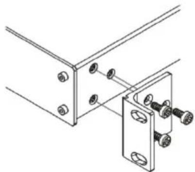
- Attach both ear brackets to the machine. To do so, remove the screws from each side of the machine (3 on each side), and replace those screws through the ear brackets.
natural_image
Technical line drawing of a mechanical bracket assembly with bolts and mounting holes (no text or symbols)- Place the ears of the machine against the rack rails, and insert the proper screws (not provided) through each of the four holes in the rack ears.
Note:
• In some models, the front panel may feature built-in rack ears
- Detachable rack ears can be removed for desktop use
• Always mount the machine in the rack before you attach any cables or connect the machine to the power
- If you are using a Kramer rack adapter kit (for a machine that is not 19"), see the Rack Adapters user manual for installation instructions available from our Web site
5 Connecting the VS-81H

Always switch off the power to each device before connecting it to your VS-81H. After connecting your VS-81H, connect its power and then switch on the power to each device.
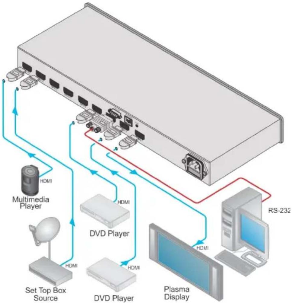
To connect the VS-81H 8x1 HDMI Switcher (as illustrated in Figure 3), do the following:
1. If required:
- Set the appropriate INPUTS to the DVD mode (see Section 6.1)
Acquire the EDID (see Section 6.2)
2. Connect the HDMI sources as follows:
You do not have to connect all the HDMI sources.
Alternatively, you can connect a PC to any of the inputs and set those inputs to the PC mode (see Section 6.1)
■ A multimedia player to INPUT 1
A set top box to INPUT 2
■ A DVD player to INPUT 6
■ A DVD player to INPUT 8
- Connect the OUTPUT HDMI connector to an HDMI acceptor (for example, a plasma display).
- If required, connect a PC and/or controller to the RS-232 port (see Section6.3) and/or the ETHERNET port (see Section 6.4).
- Connect the power connector to the mains electricity (not shown in Figure 3).
Press an INPUT SELECTOR button (from 1 to 8) to choose the HDMI input to route to the output.
flowchart
graph TD
    A["Server"] -->|HDMI| B["Multimedia Player"]
    A -->|HDMI| C["DVD Player"]
    A -->|HDMI| D["Set Top Box Source"]
    A -->|HDMI| E["DVD Player"]
    A -->|HDMI| F["Plasma Display"]
    A -->|HDMI| G["RS-232"]
Figure 3: Connecting the VS-81H 8x1 HDMI Switcher
6 Operating the VS-81H
This section describes:
• The PC mode and the DVD mode (see Section 6.1)
• How to acquire the EDID (see Section 6.2)
• How to control the machine via RS-232 (see Section 6.3)
• How to control the machine via the ETHERNET port (see Section 6.4)
6.1 The PC and DVD Modes
The VS-81H has two operation modes that can be set individually for each input: the PC mode (default) and the DVD mode:
- Use the PC mode when connecting one or more computers to the inputs using a DVI-to-HDMI converter cable
For example, the Kramer HDMI-DVI gold-plated cable in various lengths (3", 6", 10" and 15").
• Use the DVD mode when connecting one or more DVDs to the inputs
In the PC mode, an input always has access to the EDID (default or acquired) to prevent the computer from resetting if the output is not connected.
In the DVD mode, an input only has access to the EDID when it is switched to the connected output.
The PC mode and the DVD mode can be applied to a single unit or to several inputs. For example, if you want to connect computers to INPUTS 1 and 2, and DVD machines to INPUTS 6 and 8, set INPUTS 1 and 2 to the PC mode and INPUTS 6 and 8 to the DVD mode.
To set the inputs to either the PC or DVD mode, do the following:
- Turn off the VS-81H POWER.
-
Press the PANEL LOCK button while turning the POWER on again.
-
Keep pressing and holding the PANEL LOCK button for a few seconds and then release it.
The LOCK button flashes.
If an input button illuminates, this indicates that that input is set to the DVD mode.
If an input button is not illuminated, this indicates that that input is set to the PC mode. -
Press an input to toggle between the PC mode (input button not illuminated) and the DVD mode (input button illuminated).
-
To exit this mode, press the PANEL LOCK button.
-
Connect a computer to the input that is set to the PC mode and a DVD to the input that is set to the DVD mode.
The following table summarizes the differences between the PC mode and the DVD mode:
| PC Mode | DVD Mode |
| The input is connected to a computer | The input is connected to a multimedia application, such as a DVD, a set top box and so on |
| The EDID is available at all times (to prevent computer reset) | The EDID is available only when the input and an output are connected |
| The input EDID source is the default EDID or an acquired EDID (see Section 6.2) | The input EDID source is acquired directly from the connected output |
6.2 Acquiring the EDID
The acquired EDID is used when an input is set to the PC mode.
To acquire the EDID, do the following:
- Turn the POWER off.
-
Press the PANEL LOCK button and the INPUT 8 button while turning the POWER on again.
The INPUT buttons flash in sequence until the unit has completed to read the EDID. -
Release the PANEL LOCK and INPUT 8 buttons.
If an output was connected, the output EDID is read to all the inputs. If an output was not connected to the machine, the default EDID is read to the inputs.
6.3 Connecting via the RS-232 Port
You can connect to the VS-81H to a PC or RS-232 controller using the RS-232 connection.
Note that a null-modem adapter/connection is not required.
To connect to the VS-81H via RS-232:
- Connect the RS-232 9-pin D-sub rear panel port on the VS-81H unit via a 9-wire straight cable (only pin 2 to pin 2, pin 3 to pin 3, and pin 5 to pin 5 need to be connected) to the RS-232 9-pin D-sub port on your PC
6.4 Connecting via the ETHERNET Port
You can connect the VS-81H via the Ethernet, using a crossover cable (see Section 6.4.1) for direct connection to the PC or a straight through cable (see Section 6.4.2) for connection via a network hub or network router.
After connecting the Ethernet port, install and configure your Ethernet Port. For detailed instructions, see the "Ethernet Configuration (FC-11) guide.pdf" file in the technical support section on our Web site: http://www.kramerelectronics.com.
6.4.1 Connecting the ETHERNET Port directly to a PC (Crossover Cable)
You can connect the Ethernet port of the VS-81H to the Ethernet port on your PC, via a crossover cable with RJ-45 connectors.
This type of connection is recommended for identification of the factory default IP Address of the VS-81H during the initial configuration.
After connecting the Ethernet port, configure your PC as follows:
- Right-click the My Network Places icon on your desktop.
-
Select Properties.
-
Right-click Local Area Connection Properties.
-
Select Properties.
The Local Area Connection Properties window appears.
- Select the Internet Protocol (TCP/IP) and click the Properties Button (see Figure 4).
![Local Area Connection Properties General Connect using: IBM Netfinity 10/100 Ethernet Adopter Configure Components checked are used by this connection ✓ Client for Microsoft Networks ✓ File and Printer Sharing for Microsoft Networks ✓ Internet Protocol [TCP/IP] Install... Uninstall Properties Description Transmission Control Protocol/Internet Protocol. The default wide area network protocol that provides communication across diverse interconnected networks. ✓ Show icon in taskbar when connected OK Cancel](/content/2026/05/958346/images/a7fc1933f85d4020737721dd2e75d8f5c22186b83724f17b03f69a57dbf5b5e7.jpg)
Figure 4: Local Area Connection Properties Window
-
Select Use the following IP Address, and fill in the details as shown in Figure 5.
-
Click OK.
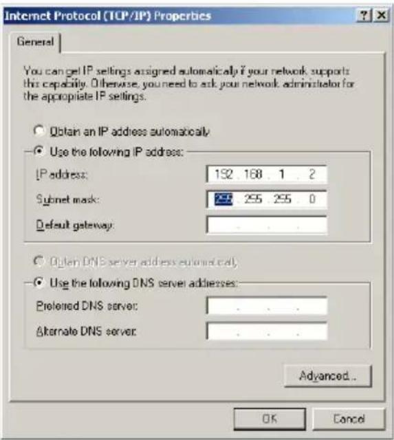
Figure 5: Internet Protocol (TCP/IP) Properties Window
6.4.2 Connecting the ETHERNET Port via a Network Hub (Straight-Through Cable)
You can connect the Ethernet port of the VS-81H to the Ethernet port on a network hub or network router, via a straight through cable with RJ-45 connectors.
6.4.3 Configuring Several Units via the Ethernet Port
To control several units via the Ethernet, connect each unit via the Ethernet port to the LAN port of your PC. Use your PC to initially configure the settings of each unit (see Section 6.46.4.1).
7 Technical Specifications
| INPUTS: | 8 HDMI connectors |
| OUTPUT: | 1 HDMI connector |
| MAX. DATA RATE: | Up to 6.75Gbps (2.25Gbps per graphic channel) |
| COMPLIANCE WITH HDMI STANDARD: | Supports HDMI and HDCP |
| RESOLUTION: | Up to UXGA; 1080p, deep color |
| POWER SOURCE: | 100–240V AC; 50/60Hz, 12VA |
| CONTROLS: | Front panel buttons, infrared remote control transmitter, RS-232, Ethernet |
| OPERATING TEMPERATURE: | 0° to +40°C (32° to 104°F) |
| STORAGE TEMPERATURE: | -40° to +70°C (-40° to 158°F) |
| HUMIDITY: | 10% to 90%, RHL non-condensing |
| DIMENSIONS: | 19" x 7" x 1U (W, D, H) |
| WEIGHT: | 2.5kg (5.5lbs) approx. |
| ACCESSORIES: | Power cord, rack “ears” and IR remote control |
| Specifications are subject to change without notice at http://www.kramerelectronics.com | |
8 Default Communication Parameters
| RS-232Protocol 2000 | |
| Baud Rate: | 9600 |
| Data Bits: | 8 |
| Stop Bits: | 1 |
| Parity: | None |
| Command Format: | HEX |
| Example (Output 1 to Input 1): | 0x01, 0x81, 0x81, 0x81 |
| Ethernet | |
| IP Address: | 192.168.1.39 |
| TCP Port Number: | 5000 |
| Network Mask: | 255.255.255.0 |
| Default Gateway: | 192.168.1.1 |
9 Protocol 2000
Kramer Protocol 2000 for RS-232/RS-485 communication uses four bytes of information as defined below.
MSB
LSB
| DESTINATION | INSTRUCTION | ||||||
| 0 | D | N5 | N4 | N3 | N2 | N1 | N0 |
| 7 | 6 | 5 | 4 | 3 | 2 | 1 | 0 |
1st byte
| INPUT | |||||||
| 1 | I6 | I5 | I4 | I3 | I2 | I1 | I0 |
| 7 | 6 | 5 | 4 | 3 | 2 | 1 | 0 |
2nd byte
| OUTPUT | |||||||
| 1 | O6 | O5 | O4 | O3 | O2 | O1 | O0 |
| 7 | 6 | 5 | 4 | 3 | 2 | 1 | 0 |
3rd byte
| MACHINE NUMBER | |||||||
| 1 | OVR | X | M4 | M3 | M2 | M1 | M0 |
| 7 | 6 | 5 | 4 | 3 | 2 | 1 | 0 |
4th byte
1st BYTE: Bit 7 - Defined as 0.
D - "DESTINATION": 0 - for sending information to the switchers (from the PC);
1 - for sending to the PC (from the switcher).
N5...N0 - "INSTRUCTION"
The function that is to be performed by the switcher(s) is defined by the INSTRUCTION (6 bits). Similarly, if a function is performed via the machine's keyboard, then these bits are set with the INSTRUCTION NO., which was performed. The instruction codes are defined according to the table below (INSTRUCTION NO. is the value to be set for N5...N0).
2nd BYTE:
Bit 7 - Defined as 1.
16...10 - "INPUT".
When switching (ie. instruction codes 1 and 2), the INPUT (7 bits) is set as the input number which is to be switched. Similarly, if switching is done via the machine's front-panel, then these bits are set with the INPUT NUMBER which was switched. For other operations, these bits are defined according to the table.
3rd BYTE:
Bit 7 - Defined as 1.
06...00 - "OUTPUT".
When switching (ie. instruction codes 1 and 2), the OUTPUT (7 bits) is set as the output number which is to be switched. Similarly, if switching is done via the machine's front-panel, then these bits are set with the OUTPUT NUMBER which was switched. For other operations, these bits are defined according to the table.
4th BYTE: Bit 7 - Defined as 1.
Bit 5 – Don't care.
OVR - Machine number override.
M4...M0 - MACHINE NUMBER.
Used to address machines in a system via their machine numbers. When several machines are controlled from a single serial port, they are usually configured together with each machine having an individual machine number. If the OVR bit is set, then all machine numbers will accept (implement) the command, and the addressed machine will reply. For a single machine controlled via the serial port, always set M4...M0 = 1, and make sure that the machine itself is configured as MACHINE NUMBER = 1.

All the values in the table are decimal, unless otherwise stated
| Instruction Codes for Protocol 2000 | ||||
| Instruction | Definition for Specific Instruction | Notes | ||
| # | Description | Input | Output | |
| 1 | SWITCH VIDEO | Set equal to video input which is to be switched(0 = disconnect) | Set equal to video output which is to be switched(0 = to all the outputs) | 2, 15 |
| 1 | SWITCH VIDEO | Set equal to video input which is to be switched(0 = disconnect) | Set equal to video output which is to be switched(0 = to all the outputs) | 2, 15 |
| 30 | LOCK FRONT PANEL | 0 - Panel unlocked1 - Panel locked | 0 | 2 |
| 31 | REQUEST WHETHER PANEL IS LOCKED | 0 | 0 | 16 |
| 61 | IDENTIFY MACHINE | 1 - video machine name2 - audio machine name3 - video software version4 - audio software version5 - RS-422 controller name6 - RS-422 controller version7 - remote control name8 - remote software version9 - Protocol 2000 revision | 0 - Request first 4 digits1 - Request first suffix2 - Request second suffix3 - Request third suffix10 - Request first prefix11 - Request second prefix12 - Request third prefix | 13 |
NOTES on the above table:
NOTE 2 – These are bi-directional definitions. That is, if the switcher receives the code, it will perform the instruction; and if the instruction is performed (due to a keystroke operation on the front panel), then these codes are sent. For example, if the HEX code
01 85 88 83 was sent from the PC, then the switcher (machine 3) will switch input 5 to output 8. If the user switched input 1 to output 7 via the front panel keypad, then the switcher will send HEX codes: 41 81 87 83
to the PC.
When the PC sends one of the commands in this group to the switcher, then, if the instruction is valid, the switcher replies by sending to the PC the same four bytes that it was sent (except for the first byte, where the DESTINATION bit is set high).
NOTE 13 – This is a request to identify the switcher/s in the system. If the OUTPUT is set as 0, and the INPUT is set as 1, 2, 5 or 7, the machine will send its name. The reply is the decimal value of the INPUT and OUTPUT. For example, for a 2216, the reply to the request to send the audio machine name would be (HEX codes):
7D 96 90 81 (i.e. 128dec+ 22dec for 2nd byte, and 128dec+ 16dec for 3rd byte).
If the request for identification is sent with the INPUT set as 3 or 4, the appropriate machine will send its software version number. Again, the reply would be the decimal value of the INPUT and OUTPUT - the INPUT representing the number in front of the decimal point, and the OUTPUT representing the number after it. For example, for version 3.5, the reply to the request to send the version number would be (HEX codes):
7D 83 85 81 (i.e. 128dec+ 3dec for 2nd byte, 128dec+ 5dec for 3rd byte).
If the OUTPUT is set as 1, then the ASCII coding of the lettering following the machine's name is sent. For example, for the VS-7588YC, the reply to the request to send the first suffix would be (HEX codes):
7D D9 C3 81 (i.e. 128dec+ ASCII for "Y"; 128dec+ ASCII for "C").
NOTE 15 – When the OVR bit (4th byte) is set, then the "video" commands have universal meaning. For example, instruction 1 (SWITCH VIDEO) will cause all units (including audio, data, etc.) to switch. Similarly, if a machine is in "FOLLOW" mode, it will perform any "video" instruction.
NOTE 16 - The reply to the "REQUEST WHETHER PANEL IS LOCKED" is as in NOTE 4 above, except that here the OUTPUT is assigned with the value 0 if the panel is unlocked, or 1 if it is locked.
For the latest information on our products and a list of Kramer distributors, visit our Web site where updates to this user manual may be found.
We welcome your questions, comments, and feedback.
Web site: www.kramerelectronics.com
E-mail: info@kramerel.com





SAFETY WARNING
D isconnect the unit from the power supply before opening and servicing

P/N: 2900-000670

Rev: 7
- Step 1: Check what's in the box
- VS-81H
- Step 2: Install the VS-81H
- Step 3: Connect the inputs and outputs
- Step 4: Connect the power
- Step 5: Operate the VS-81H
- Contents
- Introduction 1
- Getting Started 2
- Overview 4
- Figures
- Introduction
- Getting Started
- Achieving the Best Performance
- Safety Instructions
- Recycling Kramer Products
- Overview
- Defining the VS-81H 8x1 HDMI Switcher
- Installing in a Rack
- CAUTION!
- To rack-mount a machine:
- Note:
- Connecting the VS-81H
- If required:
- Connect the HDMI sources as follows:
- Operating the VS-81H
- The PC and DVD Modes
- Acquiring the EDID
- Connecting via the RS-232 Port
- Connecting via the ETHERNET Port
- Connecting the ETHERNET Port directly to a PC (Crossover Cable)
- Connecting the ETHERNET Port via a Network Hub (Straight-Through Cable)
- Configuring Several Units via the Ethernet Port
- Technical Specifications
- Default Communication Parameters
- Protocol 2000
Brand : Kramer
Model : VS-81H
Category : Network switch