JAT014108 - Heating Jocel - Free user manual and instructions
Find the device manual for free JAT014108 Jocel in PDF.


| Product Type | Electric Space Heater |
| Model | JAT014108 |
| Brand | Jocel |
| Heating Technology | Convection / Fan-Forced |
| Power Supply | 220-240 V, 50/60 Hz |
| Power Consumption | 2000 W (max) |
| Heating Levels | 2 (low / high) plus fan-only |
| Thermostat | Adjustable thermostat |
| Dimensions (W x H x D) | Approx. 25 x 40 x 15 cm |
| Weight | About 3.5 kg |
| Safety Features | Overheat protection, tip-over switch, cool-touch housing |
| Control Type | Manual knobs |
| Noise Level | < 45 dB |
| Coverage Area | Up to 25 m² |
| Energy Efficiency | Class C (typical for 2 kW heaters) |
| Maintenance | Regular dusting; clean air filter monthly |
| Spare Parts | Available: filter, thermostat, heating element |
| Warranty | 2 years (manufacturer warranty) |
| Package Contents | Heater, user manual, warranty card |
| Certifications | CE, RoHS |
Frequently Asked Questions - JAT014108 Jocel
User questions about JAT014108 Jocel
0 question about this device. Answer the ones you know or ask your own.
Ask a new question about this device
Download the instructions for your Heating in PDF format for free! Find your manual JAT014108 - Jocel and take your electronic device back in hand. On this page are published all the documents necessary for the use of your device. JAT014108 by Jocel.
USER MANUAL JAT014108 Jocel
natural_image
Exterior view of a black Jocet air fryer with visible flame and control panel (no text or symbols on body)JAT014108
MANUAL DE INSTRUCCIONES MANUAL DE INSTRUÇÕES INSTRUCTION MANUAL
APENAS PARA USO EXTERIOR.
GUARDAR ESTE MANUAL PARA REFERÊNCIA FUTURA.
SÓLO PARA USO EN EXTERIORES.
KEEP THE INSTRUCTIONS FOR FUTURE REFERENCE.
natural_image
Simple line drawing of a lamp inside a transparent cube (no text or symbols)ADVERTENCIA
LEA LAS INSTRUCCIONES ANTES DE INSTALAR Y UTILIZAR.
natural_image
Line drawing of a rectangular industrial machine with a top opening and internal components (no text or symbols)13
natural_image
Technical line drawing of a mechanical frame or enclosure with mounting brackets and a handle (no text or symbols)natural_image
Line drawing of a gas cylinder inside an open industrial storage unit (no text or symbols)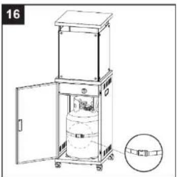
natural_image
Technical line drawing of a mechanical device with an open lid and internal cylindrical component, shown with an inset detail (no text or symbols)Telef. 00 34 914 879 573
E-mail: posventa@jocel.es
http://www.jocel.es
natural_image
Simple line drawing of a lamp inside a transparent cube (no text or symbols)AVISO
LEIA AS INSTRUÇÕES ANTES DE INSTALAR E UTILIZAR.
Hardware Utilizado

Parafuso M6x12
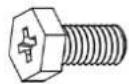
x 5

Porca M6
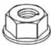
x 1
Hardware Utilizado

Parafuso M6x16
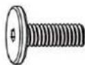
x 16

Arruela ∅ 6
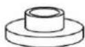
x 32
natural_image
Line drawing of a rectangular industrial machine with a central circular component and mounting bracket (no text or symbols)natural_image
Technical line drawing of a mechanical box or enclosure with mounting base and support structure (no text or symbols)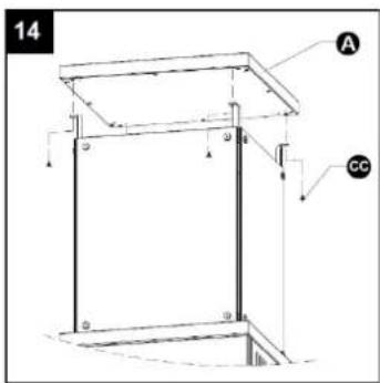
natural_image
Line drawing of a gas cylinder inside an open industrial storage cabinet (no text or symbols)natural_image
Technical line drawing of a mechanical device with open door and internal components, shown with an inset detail (no text or symbols)- Shut off gas to the appliance.
- Extinguish any open flame.
- If odor continues, immediately call your gas supplier or your fire Department.
FOR YOUR SAFETY
- Do not store or use gasoline or other flammable vapors and liquids in the vicinity of this or any other appliance.
- An LP cylinder not connected for use shall not be stored in the vicinity of this or any other appliance.
WARNING
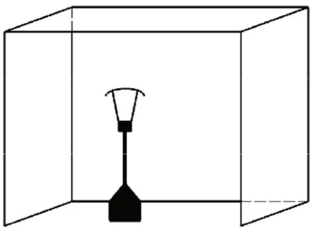
- For use outdoors or in amply ventilated areas.
- An amply ventilated area must have a minimum of 25 % of the surface area open.
- The surface area is the sum of the walls surface.
WARNING: Improper installation, adjustment, alteration, service or maintenance Can cause injury or property damage. Read the installation, operating and maintenance instructions thoroughly before installing or servicing this equipment.
natural_image
Simple line drawing of a lamp inside a transparent cube (no text or symbols)WARNING
READ THE INSTRUCTIONS BEFORE INSTALLATION AND USE.
- This appliance must be installed and the gas cylinder stored in accordance with the regulations in force;
- Do not obstruct the ventilation holes of the cylinder housing;
- Do not move the appliance when in operation;
- Shut off the valve at the gas cylinder or the regulator before moving the appliance;
- The tubing or the flexible hose must be changed within the prescribed intervals;
- Use only the type of gas and the type of cylinder specified by the manufacturer;
- Do not use the appliance in big wind weather.
It is advisable to use a protection guard. Failure to use this guard will result in a potential hazard to clothing when approaching the appliance;
The protection guard is not supplied with the appliance, the installer shall install the guard according to local rules in force and advise the fitting of the manufacturer's dress guard. Installer shall also warn the user of the hazard caused to clothing by open flames if the dress guard is not fitted. Manufacturer's glass dress guard is in the diameter 500mm and in the height 300mm. The glass should be the material of silica glass, which shall craze to smaller pieces in order not harm to user. Recommendation, for any additional guard that may be required for the protection of young children, aged or infirm persons; Keep the appliance at least 1m from the gas cylinder.
A regulator (complies with EN16129:2013 and the national regulation) of the correct pressure corresponding to the appliance category.
Use 30mbar regulator for butane/propane under the category I3B/P(30).
Use 30mbar regulator for butane under the category I3+(28-30/37).
Use 37mbar regulator for propane under the category I3+(28-30/37).
Use 50mbar regulator for butane/propane under the category I3B/P(50).
It's recommended to use flexible hose that approved by EN16436:2014.
TABLE OF CONTENTS
CAUTION 42
HEATER STAND AND LOCATION 43
GAS REQUIREMENTS 44
LEAKAGE TEST 44
CLEANING AND CARE 46
PARTS AND SPECIFICATIONS 46
ASSEMBLY PARTS AND PROCEDURES 48
PROBLEMS CHECK LIST 54
WARRANTY 55
DECLARATION OF CONFORMITY 56
CAUTION
PLEASE READ CAREFULLY THE FOLLOWING SAFETY GUIDELINES BEFORE OPERATION.
- Do not use the fire pit for indoors, as it may cause personal injury or property damage.
- This outdoor fire pit is not intended to be installed on recreational vehicles and/or boats.
• Installation and repair should be done by a qualified service person. - Improper installation, adjustment, alteration can cause personal injury or property damage.
- Do not attempt to alter the unit in any manner.
- Never replace or substitute the regulator with any regulator other than the factory-suggested replacement.
- Do not store or use gasoline or other flammable vapors or liquids in the heater unit.
- The whole gas system, hose, regulator, pilot or burner should be inspected for leaks or damage before use, and at least annually by a qualified service person.
- All leak tests should be done with a soap solution. Never use an open flame to check for leaks.
- Do not use the heater until all connections have been leak tested.
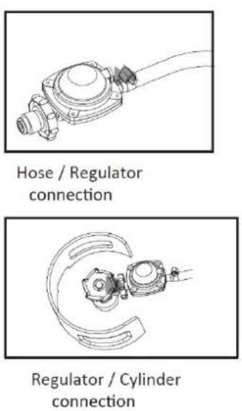
- Turn off the gas valve immediately if smell of gas is detected. Turn Cylinder Valve OFF. If leak is at Hose/Regulator connection: tighten connection and perform another leak test. If bubbles continue appearing should be returned to hose's place of purchase. If leak is at Regulator/Cylinder Valve connection: disconnect, reconnect, and perform another leak check. If you continue to see bubbles after several attempts, cylinder valve is defective and should be returned to cylinder's place of purchase.
- Do not transport heater while it's operating.
- Do not move the heater after it has been turned off until the temperature has cooled down.
- Keep the ventilation opening of the cylinder enclosure free and clear of debris.
- Do not paint the radiant screen, control panel or top canopy reflector.
- Control compartment, burner and circulation air passageways of the heater must be kept clean.
- Frequent cleaning may be required as necessary.
- The LP tank should be turned off when the heater is not in use.
- Check the fire p i t immediately if any of the following occurs:
- The fire pit does not reach temperature.
- The burner makes popping noise during use (a slight noise is normal when the burner is extinguished).
- Smell of gas in conjunction with extreme yellow tipping of the burner flames.
- The LP regulator/hose assembly must be located out of pathways where people may trip over it or in area where the hose will not be subject to accidental damage.
- Any guard or other protective device removed for servicing the heater must be replaced before operating the fire pit.
- Adults and children should stay away from high temperature surface to avoid burns or clothing ignition.
- Children should be carefully supervised when they are in the area of the fire pit.
- Clothing or other flammable materials should not be hung on the heater or placed on or near the fire pit.
- To change the gas cylinder in a amply ventilated area, away from any ignition source (candle, cigarettes, other flame producing appliances, ...);
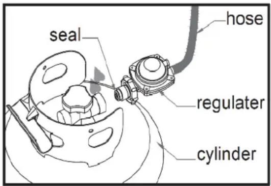
- To check that the regulator seal is correctly fitted and able to fulfill its function showed as photo right;
- To not obstruct the ventilation holes of the cylinder housing;
- To close the gas supply at the valve of the gas cylinder or the regulator after use;
- In the event of gas leakage, the appliance shall not be used or if alight, the gas supply shall be shut off and the appliance shall be investigated and rectified before it is used again;
- To check the hose at least once per month, each time the cylinder is changed, or each time before long time no use.
- If it shows signs of cracking, splitting or other deterioration it shall be exchanged for new hose of the same length and of the equivalent quality;
- The use of this appliance in enclosed areas can be dangerous and is PROHIBITED;
- Read the instructions before using this appliance. The appliance must be installed in accordance with the instructions and local regulations.
- For connection of hose and regulator, and connection of regulator and hose, please refer to photo showed above.
HEATER STAND AND LOCATION
- The heater is primarily for outdoor use only. Always ensure that adequate fresh air ventilation is provided.
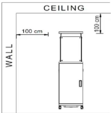
- Always maintain proper clearance to combustible materials, i.e. top 100 cm and sides 100 cm minimum.
- Heater must be placed on level firm ground.
- Never operate heater in an explosive atmosphere like in areas where gasoline or other flammable liquids or vapors are stored.
GAS REQUIREMENTS
- Use propane, butane or their mixtures gas only.
- The pressure regulator and hose assembly to be used must conform to local standard codes.
- The installation must conform to local codes, or in the absence of local codes, with the standard for the storage and handling of liquid petroleum gases.
- A dented, rusted or damaged tank may be hazardous and should be checked by your tank supplier. Never use a tank with a damaged valve connection.
- The tank must be arranged to provide for vapor withdrawal from the operating cylinder.
- Never connect an unregulated tank to the heater.
LEAKAGE TEST
Gas connections on the heater are leak tested at the factory prior to shipment. A complete gas tightness check must be performed at the installation site due to possible mishandling in shipment or excessive pressure being applied to the heater.
- Make a soap solution of one part liquid detergent and one part water. The soap solution can be applied with a spray bottle, brush or rag. Soap bubbles will appear in case of a leak.
- The heater must be checked with a full cylinder.
- Make sure the safety control valve is in the OFF position.
- Turn the gas supply ON.
- In case of a leak, turn off the gas supply. Tighten any leaking fittings, then turn the gas supply on and recheck.
- Never leak test while smoking.
Warning: User shall pour glass beads fully to cover the whole burner before operation.
TO TURN ON THE FIRE PIT
- Be sure the control knob is in the "OFF" position (Figure a).
- Fully open LP cylinder valve.
Note: For initial start or after any cylinder change, hold Control Knob in for 10 seconds to purge air from gas lines before proceeding.
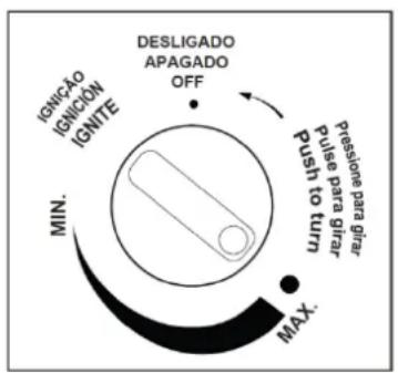
- Push in gas control knob and turn counterclockwise to "IGNITER" (Figure b) to light the fire pit. If needed, keep depressing and turning control knob counterclockwise until the heater lights (You should hear a clicking sound).
- After fire pit lights, release control knob. Push in and turn the control knob to the "MAX", then release control knob. If you want a lower temperature, push in the control knob and turn clockwise to the "MIN." (Figure c).
Note: If burner fails to remain lit, all valves should be closed and a waiting period of at least 5 minutes should pass before attempting to light.
TO TURN OFF THE FIRE PIT
- To extinguish burner, push in the control knob and continue to turn it clockwise to OFF.
- Turn cylinder valve clockwise to OFF and disconnect regulator when fire pit is not in use.
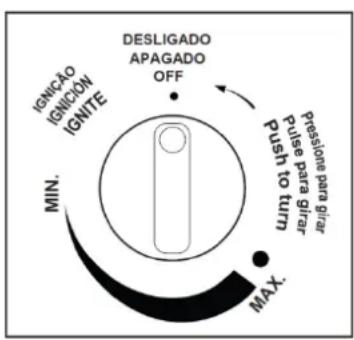
Figure a
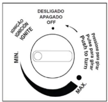
Figure b
- Always close the gas valve of the gas cylinder after use or in case of a disturbance.
- Remove the pressure controller and the hose.
- Check the tightness of the gas valve and for damage. If you suspect a damage, have it changed by your gas dealer.
- Never store liquid gas cylinder in a sub-terrain, or at places without adequate air ventilation.
CLEANING AND CARE
- Wipe off powder coated surfaces with soft, moist rag. Do not clean heater with cleaners that are combustible or corrosive.
- Remove debris from the burner to keep it clean and safe for use.
- Cover the burner unit with the optional protective cover when the heater is not in use.
PARTS AND SPECIFICATIONS
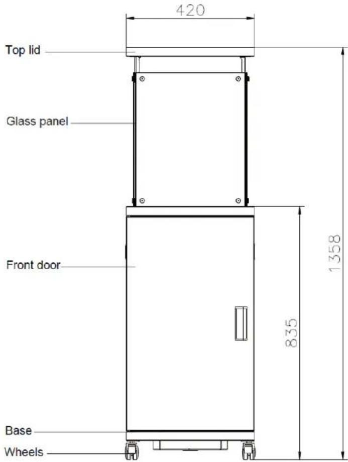
A. CONSTRUCTION AND CHARACTERISTICS
- Transportable terrace/fire pit with tank housing.
- Casing in steel with black powder-coating.
• Gas hose connections with metal clamp.
B. SPECIFICATIONS
• Use propane, butane or their mixtures gas only.
• Max. wattage: 13000 watts
- Consumption:
| APPLIANCE CATEGORY: | I3+(28-30/37) | I3B/P(30) | I3B/P(50) | I3B/P(37) | |
| TYPES OF GAS: | Butane | Propane | Butane, propane or their mixtures | Butane, propane or their mixtures | Butane, propane or their mixtures |
| GAS PRESSURE: | 28-30 mbar | 37 mbar | 30 mbar | 50 mbar | 37 mbar |
| OUTLET PRESSURE O REGULATOR: | 30 mbar | 37 mbar | 30 mbar | 50 mbar | 37 mbar |
- Using the proper regulator according to outlet pressure of regulator as showed in the table above.
C. TABLE OF INJECTOR
| APPLIANCE CATEGORY: | I3+(28-30/37) | I3B/P(30) | I3B/P(50) | I3B/P(37) | |
| TYPES OF GAS: | Butane | Propane | Butane, propane or their mixtures | Butane, propane or their mixtures | Butane, propane or their mixtures |
| GAS PRESSURE: | 28-30 mbar | 37 mbar | 30 mbar | 50 mbar | 37 mbar |
| TOTAL HEAT INPUT (Hs): (Qn) | 13kW (G30:946g/h; G31:929g/h) | ||||
| INJECTOR SIZE: | 1.90 mm for main burner | 1.70 mm for main burner | 1.8 mm for main burner | ||
| The marking, for example, 1.90 on the injector , indicates that the size of injector is 1.90mm | |||||
- The hose and regulator assembly must conform to local standard codes.
- Regulator outlet pressure should meet the corresponding appliance category in B. Specification.
- The appliance requires approved hose in 0.6m length.
ASSEMBLY PARTS
TOOLS NEEDED:
• Philips screwdriver w/ medium blade.
- Spray bottle of soap solution for leakage test.
PARTS LIST:
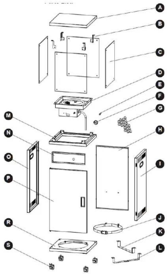
| PART | DESCRIPTION | QUANT. |
| A | Top lid | 1 |
| B | Top lid Support | 4 |
| C | Glass panel | 4 |
| D | Burner | 1 |
| E | Valve pole | 1 |
| F | Control knob | 1 |
| G | Lava rock (decorative) | 1 |
| H | Back panel | 1 |
| I | Right side panel | 1 |
| J | Gas cylinder Fixed bracket | 1 |
| K | Gas cylinder bracket A | 1 |
| L | Gas cylinder bracket B | 1 |
| M | Gas cylinder housing Upper cover | 1 |
| N | Control panel | 1 |
| O | Left side panel | 1 |
| P | Front door | 1 |
| R | Base | 1 |
| S | Wheels | 4 |
ASSEMBLY PARTS
HARDWARE CONTENTS
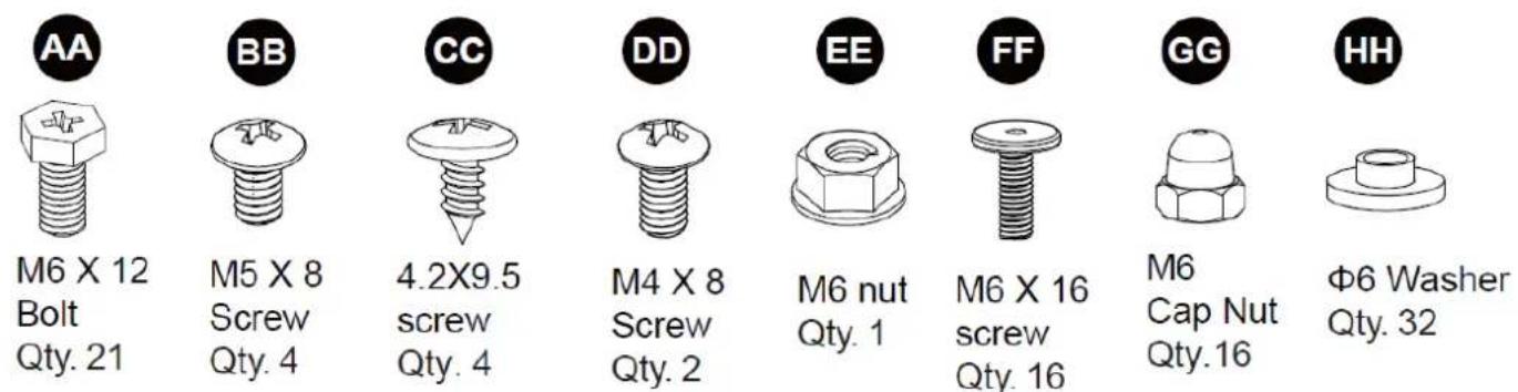
M6 X 12
Bolt
Qty. 21
M5 X 8
Screw
Qty. 4
4.2×9.5
screw
Qty. 4
M4 X 8
Screw
Qty. 2
M6 nut Qty. 1
M6 X 16 screw Qty. 16
M6
Cap Nut Qty.16
Φ6 Washer Qty. 32

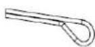
Cotter pin Qty.1

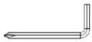
Philips
screwdriver
Qty. 1

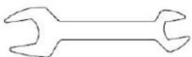
Wrench
Qty. 1

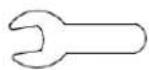
Wrench
Qty. 1
ASSEMBLY INSTRUCTIONS
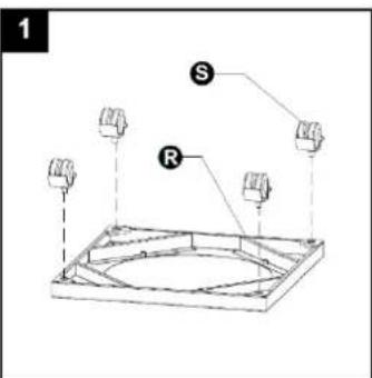
- Install the four wheels on the base.
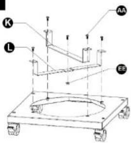
2.1 Install the gas cylinder brackets A and B to the base with four M6X12 hexagon screws.
2.2 Use one M6X12 hexagon screw and one M6 hexagon flange nuts between the two gas cylinder brackets, and then tighten the screws.
Hardware Used

M6 X 12 Bolt
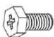
× 5

M6 nut

x 1
2
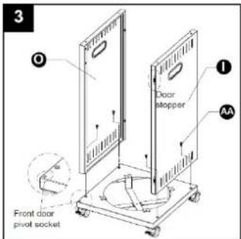
- Install the left side plate and the right-side plate to the chassis with four M6X12 hexagon screws. Note that the side plate without door suction is the left side plate, which is installed to the side with front door hole, and the right-side plate with door suction is installed to the other side).
Hardware Used

M6 X 12 Bolt
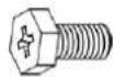
× 4
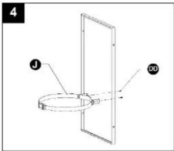
- Install the gas cylinder bracket on the inner side of the 4 black plate with two M4 X8 screws.
Hardware Used

M4 X 8 Screw

×2
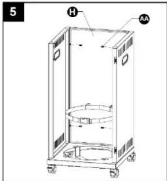
- Install the back plate on the left and right-side plates with four M6X12 hexagon screws (note that the gas cylinder bracket should be located on the lower side.
Hardware Used

M6 X12 bolt
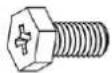
× 4
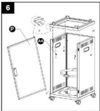
6.1. Insert the rotating shaft in the lower left corner of the front door into the rotating shaft hole of the chassis.
6.2. Straighten the front door, then place the upper plate of the box on the left and right-side plates of the box, and insert the rotating shaft at the upper left of the front door into the rotating shaft hole at the lower left of the upper plate of the box.
6.3. Adjust the position of the upper plate of the box body and the left and right-side plates, so that the mounting screw holes at the bottom of the upper plate of the box body are aligned with the mounting holes of the left and right-side plates, and tighten the upper plate of the box body from the inside with four M6X12 hexagon screws.
Hardware Used

M6 X12 bolt
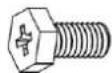
× 4
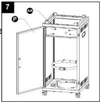
- Install the round hole of the control panel to the right in 7 the middle of the top of the left and right-side plates, fix it with four M6X12 hexagon screws, close the front door, adjust the gap between the front door and the upper plate of the box, then open the front door and tighten the screws. Adjust the installation so that the front door can have a uniform gap with the upper plate and chassis of the box. If the control panel cannot be smoothly placed between the left and right-side plates, loosen the screws A and B in the previous step, and then tighten the screws A and B after this step is assembled.
Hardware Used

M6 X12 bolt
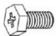
× 4
- Put the valve rod of the burner head forward into the upper part of the box body, and screw the burner head on the upper plate of the box body with four M5X8 screws.
Hardware Used

M5 X 8 Screw

× 4
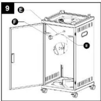
- Insert the valve extension rod into the valve stem through the round hole of the control panel, then insert the knob into the extension rod and press it inward. Then insert a cotter pin into the anti-dropping hole of the extension rod communicated with the valve stem from the inside and bend the cotter pin.
Hardware Used

Cotter pin
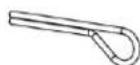
× 1
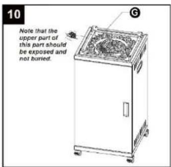
- Pour the Lava Rock (decorative), and the upper part of the ignition protection cover needs to be exposed.

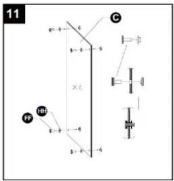
- As shown in the figure
11.1 firstly, insert the convex surface of the T-shaped silicone hot plate into the M6X16 hexagon socket head screw, and push the gasket to the end of the screw.
11.2 Then, put the screws inserted into the silica gel gasket in step 1 into the holes at the four corners of the glass in the same direction in turn.
11.3 Put the convex surface of the silicone gasket into the screw from the back towards the glass, and press the screw to make it in close contact with the silicone gasket on the back.
Hardware Used

M6 X 16 Screw
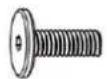
× 16

Φ6 Washer
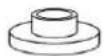
× 32
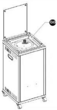
12.1 Insert the pre-placed screw in step 11 and two screws at one end of toughened glass of silica gel gasket into the holes of brackets at both ends of the upper part of the box, screw M6 cap nuts from the inside, and adjust the position of toughened glass to the center.
12.2 Assemble the remaining pieces of tempered glass to the box in turn according to the steps.
12.3 Adjust the gap at the bottom of each glass to be even, then screw the screws until the silica gel gaskets on both sides of the glass completely fit the glass, and then continue to tighten the nuts for half a turn.
Hardware Used

M6 Cap Nut

×8
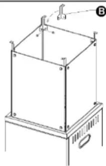
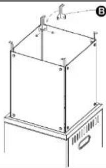
13.1 Insert the two mounting holes in the lower part of the top cover bracket into the screws in the upper corner of the tempered glass cover, and then tighten the screws by the method of step 11.
13.2 Install the remaining 3 roof brackets in turn.
Hardware Used

M6 Cap Nut

×8
12
natural_image
Line drawing of a portable industrial machine with a top-mounted lid and mounting bracket (no text or symbols)13
natural_image
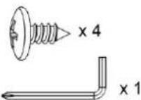
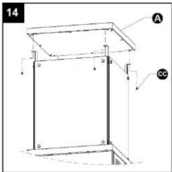
Technical line drawing of a mechanical assembly with mounting brackets and a base (no text or symbols)- Place the top cover on the four top cover brackets, and adjust the screw holes on the left side of the four corners of the top cover to align with the mounting holes of the top cover brackets. Fix the top cover and the bracket with 4 pcs 4.8x9.5 tapping screws.
Hardware Used

4.2X9.5 screw

Philips screwdriver
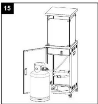
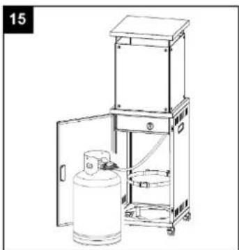
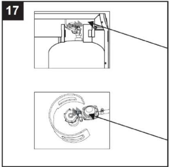
- Connect hose and regulator to cylinder.
The propane gas and cylinder are sold separately.
natural_image
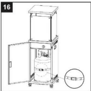
Line drawing of a gas cylinder inside an open industrial storage unit (no text or symbols)- Propane Only-Proper Hose Connection.
⚠ WARNING! Ensure the hose does not contact any high temperature surfaces, or it may melt and leak causing a fire. After the cylinder is placed inside the heater, secure the cylinder with block belt tightly.
natural_image
Technical line drawing of a mechanical device with open door and internal components, shown with an inset magnified view (no text or symbols)- Leak Check.

WARNING! A leak test must be performed annually and each time a cylinder is hooked up or if a part of the gas system is replaced.

WARNING! Never use an open flame to check for gas leaks. Be certain no sparks or open flames are in the area while you check for leaks. Sparks or open flames will result in a fire or explosion, damage to property, serious bodily injury, or death.

Leak testing: This must be done before initial use, annually, and gas Components are replaced or serviced. Do not smoke while performing this test, and remove all sources of ignition. See Leak Testing Diagram for areas to check. Turn all burner controls to the off position. Turn gas supply valve on.

Brush a half-and-half solution of liquid soap and water onto all joints and connections of the regulator, hose, manifolds and valves.

Bubbles will indicate a gas leak. Either tighten the loose joint or have the part replaced with one recommended by the Customer Care department and have the patio heater inspected by a certified gas installer.
If the leak cannot be stopped, immediately shut off the gas supply, disconnect it, and have the patio heater inspected by a certified gas installer or dealer. Do not use the patio heater until the leak has been corrected.
PROBLEMS CHECK LIST
| PROBLEM | PROBABLE CAUSE | SOLUTION |
| Burner will not light | Pressure is lowOpening blockedControl not ONThermocouple badPilot light assembly bentNot in correct location | Tank near empty. Refill LPG tank.Remove and clean.Turn valve to ON.Replace thermocouple.Place pilot properly.Position properly and retry. |
GENERAL WARRANTY TERMS
- The warranty is valid only on presentation of invoice of purchase.
- This WARRANTY is limited exclusively to parts substitution ineffective due to faulty manufacture, made in our workshops.
- The elimination of several faults of the scope of the guarantee is made for repair or replacement of defective parts, according to the discretion of our technical services. Defective parts are our property.
- Are not covered under warranty damage caused by transportation, neglect or poor use, improper assembly or installation, as well as external influences such as: lightning strikes or power, flooding, humidity, etc.
- Lose warranty, all appliances that are not being used according to the instructions or connected to FEEDING NETWORKS not guarantee a constant voltage of 220/240V.
- The warranty does not cover damages for personal injury or damage caused directly or indirectly in any capacity whatsoever.
- This warranty terminates when it is found to have been undergoing repairs, alterations or interventions by any person not authorized by Jocel.
THE WARRANTY EXPIRES
- If the appliance has not been installed by an Accredited Technician.
- Exceeded the period for home appliances and for industrial appliances, warranty expires and assistance will be made by charging the costs of manpower, according to current fees.
- With the modification or disappearance of the nameplate of the appliance.
NOTE: GLASSES AND LAMPS ARE NOT COVERED BY WARRANTY.
TECHNICAL ASSISTANCE
For technical assistance request, our services are available through the following contacts:
Telef. 00 351 252 910351 Fax: 00 351 252 910367 E-mail: assistencia@jocel.pt http://www.jocel.pt
HEADQUARTERS:
Rua Alto do Curro, n.º 280
4770-569 S. COSME DO VALE
V.N. de FAMALICÃO
Telef: 252 910 350/2
Fax: 252 910 368/9
email: jocel@jocel.pt
http://www.jocel.pt
DECLARATION OF CONFORMITY
CE
We declare on our own responsibility that the machine indicated below
Product PATIO HEATER
Brand JOCEL
Model JAT014108
Complies with the following European directives and standards implementation:
Gas Appliances
(EU) 2016/426
EN 14543:2017
MADE R.P.C.
- MANUAL DE INSTRUCCIONES MANUAL DE INSTRUÇÕES INSTRUCTION MANUAL
- ADVERTENCIA
- LEA LAS INSTRUCCIONES ANTES DE INSTALAR Y UTILIZAR.
- AVISO
- LEIA AS INSTRUÇÕES ANTES DE INSTALAR E UTILIZAR.
- Hardware Utilizado
- FOR YOUR SAFETY
- WARNING
- READ THE INSTRUCTIONS BEFORE INSTALLATION AND USE.
- TABLE OF CONTENTS
- CAUTION
- HEATER STAND AND LOCATION
- GAS REQUIREMENTS
- LEAKAGE TEST
- TO TURN ON THE FIRE PIT
- TO TURN OFF THE FIRE PIT
- CLEANING AND CARE
- PARTS AND SPECIFICATIONS
- CONSTRUCTION AND CHARACTERISTICS
- SPECIFICATIONS
- TABLE OF INJECTOR
- ASSEMBLY PARTS
- TOOLS NEEDED:
- HARDWARE CONTENTS
- ASSEMBLY INSTRUCTIONS
- Hardware Used
- GENERAL WARRANTY TERMS
- THE WARRANTY EXPIRES
- TECHNICAL ASSISTANCE
- DECLARATION OF CONFORMITY
- CE
Brand : Jocel
Model : JAT014108
Category : Heating