
10A35 - Electronic board Daytronic - Free user manual and instructions
Find the device manual for free 10A35 Daytronic in PDF.


| Product Type | Signal Conditioning Module |
| Brand | Daytronic |
| Model | 10A35 |
| Dimensions (H x W x D) | 2.0 x 5.0 x 6.0 inches (approx.) |
| Weight | 1.5 lbs (approx.) |
| Power Supply | 115/230 VAC, 50/60 Hz, 10 W |
| Input Channels | 1 Channel |
| Input Signal Type | Strain Gage, Load Cell, Pressure Transducer |
| Excitation Voltage | 10 VDC (adjustable) |
| Output Signal | ±10 VDC, 4-20 mA |
| Bandwidth | DC to 10 kHz |
| Linearity | ±0.01% of full scale |
| Zero and Span Adjustment | Multiturn potentiometers |
| Filter Options | Low-pass filter (selectable cutoff) |
| Operating Temperature | 0°C to 50°C |
| Storage Temperature | -20°C to 70°C |
| Humidity | 0-95% non-condensing |
| Mounting | Panel mount or rack mount (optional adapter) |
| Safety | CE compliant, overvoltage protection |
| Maintenance | Periodic calibration check; clean with dry cloth |
| Spare Parts | Replacement excitation board, output connector |
Frequently Asked Questions - 10A35 Daytronic
User questions about 10A35 Daytronic
0 question about this device. Answer the ones you know or ask your own.
Ask a new question about this device
Download the instructions for your Electronic board in PDF format for free! Find your manual 10A35 - Daytronic and take your electronic device back in hand. On this page are published all the documents necessary for the use of your device. 10A35 by Daytronic.
USER MANUAL 10A35 Daytronic
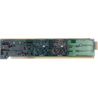
This single-channel, phase-encoded conditioner may be used with incremental encoder sensors whose outputs are quadratured to indicate “travel” and “direction of travel,” for measurement of relative linear or angular displacements over a very wide range of distances and precisions.
The 10A35 generates a count per 90° phase shift, with a maximum allowable count of ±32700 and a speed limitation of 50 kHz, maximum. To accommodate the largest number of transducers, this count may be predivided by any integer from 1 to 256, as explained in Section 3.a. The 10A35 allows run-time “zero indexing” (resetting) and restarting of a channel’s count reading by the operator or host computer. There are also input provisions for a user-supplied auxiliary external power supply from 9 to 15 V-DC, which would allow you to keep the count “alive” during system power shut-down.
NOTE: A System 10 data channel derived from a Model 10A35 always takes a channel "type" code of CA, and does not require calibration.
ADDITIONAL 10A35 SPECIFICATIONS
Input Signals: ZERO INDEX (RESET), PHASE 1 (SINE), and PHASE 2 (COSINE); each input is available as a "TTL INPUT" or a "LOW-LEVEL INPUT"
Excitation: Nominal 5 V-DC; 50 mA maximum
Accuracy: Based on transducer, ± 1 digit
Auxiliary Power Supply: 9 to 15 V-DC
Auxiliary Outputs to Mainframe Wire-Wrap Pins: None
2 TRANSDUCER CONNECTIONS
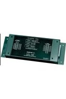
The Model 10A35's I/O CONNECTOR mates with Daytronic CONDITIONER CONNECTOR No. 60322, shown in Fig. 1.5 (in Manual Section 1.E.1). Standard cable connections—including connection of an optional "keep-alive" power supply—are given in Fig. 1, below. Table 1 gives standard pin assignments for the I/O Connector.
The 10A35 takes three input signals: ZERO INDEX (RESET), PHASE 1 (SINE), and PHASE 2 (COSINE). Each input is available as a "TTL INPUT" or a "LOW-LEVEL INPUT." With internal pull-up less than 1 LSTTL load, TTL INPUTS (Pins 3, C, and 5) are for use with transducers with high output levels greater than 2.4 V-DC. With 15-kΩ impedance, LOW-LEVEL INPUTS (Pins 4, D, and E) are 200 mV minimum and 9 V maximum without damage, and are for use with transducers with high output levels of 200 mV-DC to 2.4 V-DC. Low transducer output is less than 0.8 V-DC for TTL, and less than 50 mV for LOW-LEVEL.
An excitation of +5 V-DC is provided by the 10A35, as shown in Fig. 1. If a higher excitation level is required, the user must provide his or her own external supply, in which case the 10A35's EXCITATION OUTPUT (Pin1) should NOT be connected to the sensor.
The 10A35 has input provisions for a user-supplied external power supply from 9 to 15 V-DC. This external ("Auxiliary") supply would allow you to keep the count "alive" during system power shut-down. The optional "keep-alive" supply should be connected to Pins A and 2, as shown in the figure.
ALSO NOTE: When Pin 5 (ZERO INDEX TTL INPUT) is not used, it must be tied to COMMON (Pin 2).
Table 1 Model 10A35 Pin Assignments
| I/O Connector ConditionerPin LineNumber Function | ||
| 1 EXCITATION OUTPUT (+5 V-DC)A AUXILIARY POWER SUPPLY INPUT | ||
| 2 | C | O |
| B Not Committed | ||
| 3 | S | INE TTL INPUT |
| C COSINE TTL INPUT | ||
| 4 SINE LOW-LEVEL INPUT | ||
| D COSINE LOW-LEVEL INPUT | ||
| 5 | ZERO INDEX TTL INPUT | |
| E ZERO INDEX LOW-LEVEL INPUT | ||
| 6-10 | Not Committed | |
| F-L Not Committed | ||
Fig. 1 Model 10A35 Transducer Cabling

flowchart
graph TD
    A["9 - 15 V-DC Auxiliary Power Supply"] --> B["EXCITATION (+5 V)"]
    B --> C["COSINE"]
    B --> D["SINE"]
    B --> E["ZERO INDEX"]
    B --> F["COMMON"]
    G["CONDITIONER CONNECTOR (No. 60322)"] --> H["See Note on Pin 5"]
    H --> I["A 1"]
    H --> J["B 2"]
    H --> K["C 3"]
    H --> L["D 4"]
    H --> M["E 5"]
    H --> N["F 6"]
    H --> O["H 7"]
    H --> P["J 8"]
    H --> Q["K 9"]
    H --> R["L 10"]
    S["SHIELD"] --> T["Connector pins shown as viewed from rear (cable) side of connector"]
    U["Ground Lug"] --> V["Common"]
    W["SINETTL"] --> X["SINE TIL"]
    W --> Y["SINE LOW-LEVEL"]
SETUP AND/OR OPERATING CONSIDERATIONS
For initial configuration of the ANALOG INPUT CHANNEL dedicated to a specific Model 10A35 card when used in System 10, see the general remarks on System 10 "real-channel" configuration in Manual Section 1.G.1 and elsewhere in the System 10 Guidebook. A 10A35 channel will always take a "type" code of CA.
COUNT PREDIVISION
To predivide the count represented by a 10A35-based Channel No. "x" by any integer from 1 through 256, you should apply the following RANGE (RNG) command:
$$ \mathrm{RNG} \times = 0 0 \mathrm{h} [ \mathrm{CR} ] $$
The term to the right of the equals sign consists of two zeros, followed by a two-character hexadecimal number ("h") from 00 through FF. The decimal equivalent of the hexadecimal number "h" is to be one less than the value of the integral divisor by which the count is to be predivided. Note that the system EEPROM SWITCH does NOT need to be ON for the above RNG command to work.
Thus, for example, a “full count” of ±32700 would call for a hexadecimal value of “00” for “h,” which will enter a divisor of (decimal) “1.” A divisor of, say, “100” would yield a full count of ±327, and would be entered by a value for “h” of hexadecimal “63” (equivalent to decimal “99”). See also the example under “Returning the 10A35 to 'RUN MODE'," below.
IMPORTANT: Unless an external power supply has been connected, you must use the RANGE (RNG) command following every system powerup, to reset the 10A35 and to return it to "RUN MODE," as explained in the following sections.
ZERO-INDEXING (RESETTING) THE 10A35
You will use the following form of the RANGE (RNG) command to "zero-index" a 10A35-based Channel No. "x" (that is, to reset its count to zero):
$$ R N G x = 8 0 h [ C R ] $$
Here, the term to the right of the equals sign consists of the numbers "8" and "0," followed by the desired divisor code "h" (explained above). Again, the system EEPROM SWITCH does NOT need to be ON for this command to work.
RETURNING THE 10A35 TO "RUN MODE"
The effect of the RNG x = 80h [CR] command (above) is to place the 10A35 in "RESET MODE." IT WILL REMAIN IN RESET MODE UNTIL APPLICATION OF A RANGE (RNG) COMMAND OF THE FORM
$$ R N G x = 0 0 h [ C R ] $$
Suppose, for example, that your Model 10A35 uses Channel No. 101, and that you have set it for a full count of ±3270 by a command of
$$ R N G 1 0 1 = 0 0 0 9 [ C R ] $$
(here, since your desired count divisor is "10," you will enter for "h" the hexadecimal equivalent of "10 minus 1," or "9"). To zero-index the 10A35 at any subsequent time, you need only command
RNG 101 = 8009 [CR]
To then restart the 10A35's count (from zero), you would again command
RNG 101 = 0009 [CR]



Brand : Daytronic
Model : 10A35
Category : Electronic board