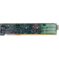
AA41-4F010 - Electronic board Daytronic - Free user manual and instructions
Find the device manual for free AA41-4F010 Daytronic in PDF.


Pick your language and provide your email: we'll send you a specifically translated version.
| Product Type | Signal Conditioner / Amplifier |
| Brand | Daytronic |
| Model | AA41-4F010 |
| Dimensions (H x W x D) | 90 mm x 50 mm x 150 mm |
| Weight | 0.5 kg |
| Power Supply | 24 VDC, 100 mA max |
| Input Signal | ±10 V, 0-20 mA, or bridge (strain gauge) |
| Output Signal | ±10 V, 0-10 V, or 4-20 mA |
| Bandwidth | 0 to 50 kHz |
| Gain Range | 1 to 1000, adjustable |
| Filtering | Low-pass filter, adjustable cutoff |
| Excitation | 10 VDC, 50 mA for bridge sensors |
| Connector Type | Screw terminals and DB-9 for I/O |
| Mounting | DIN rail or panel mount |
| Operating Temperature | 0°C to 50°C |
| Protection Rating | IP20 (enclosed) |
| Safety | Overvoltage and reverse polarity protection |
| Maintenance | Periodic calibration check recommended every 12 months |
| Spare Parts Availability | Contact Daytronic customer service |
| Reparability | Serviceable by qualified technician; no user-serviceable parts |
Frequently Asked Questions - AA41-4F010 Daytronic
What is the typical application of the Daytronic AA41-4F010?
The AA41-4F010 is a signal conditioner used for strain gauge, LVDT, or other bridge-type sensors in industrial measurement and control systems.
What power supply voltage does the device require?
It requires a 24 VDC power supply with a current consumption of 100 mA maximum.
How do I calibrate the AA41-4F010?
Calibration involves adjusting the zero and span trimmers using a known input. Refer to the user manual for detailed steps. It is recommended to perform calibration annually.
What output signals can be obtained from the device?
The device provides analog output options: ±10 V, 0-10 V, or 4-20 mA, selectable via jumpers or dip switches.
Can the AA41-4F010 be used with 4-20 mA sensors?
Yes, it can accept 0-20 mA input signals, but for a standard 4-20 mA loop, a precision resistor may be required to convert current to voltage.
What is the maximum input voltage range?
The maximum differential input voltage is ±10 V. Exceeding this may damage the device. For bridge inputs, the excitation is 10 VDC.
Does the device have built-in filtering?
Yes, it includes a low-pass filter with an adjustable cutoff frequency to reduce noise. The cutoff can be set via a potentiometer.
What type of connectors does the device use?
The device uses screw terminals for power and I/O connections, and a DB-9 connector for optional remote configuration or monitoring.
Can the AA41-4F010 be mounted on a DIN rail?
Yes, the device is designed for DIN rail mounting and also includes screw holes for panel mounting with optional brackets.
Where can I find spare parts or repair service?
Spare parts and repair services are available through Daytronic customer support. The device should be returned for servicing if malfunctioning.
User questions about AA41-4F010 Daytronic
0 question about this device. Answer the ones you know or ask your own.
Ask a new question about this device
No questions yet. Be the first to ask one.
Download the instructions for your Electronic board in PDF format for free! Find your manual AA41-4F010 - Daytronic and take your electronic device back in hand. On this page are published all the documents necessary for the use of your device. AA41-4F010 by Daytronic.
USER MANUAL AA41-4F010 Daytronic



Manual assistant
Powered by Anthropic
Waiting for your message
Product information
Brand : Daytronic
Model : AA41-4F010
Category : Electronic board