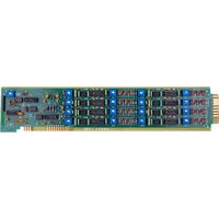
10A15-8 - Electronic board Daytronic - Free user manual and instructions
Find the device manual for free 10A15-8 Daytronic in PDF.


| Brand | Daytronic |
| Model | 10A15-8 |
| Product Type | Signal Conditioning Module |
| Dimensions (H x W x D) | 200 x 150 x 50 mm (7.9 x 5.9 x 2.0 in) |
| Weight | 0.5 kg (1.1 lb) |
| Power Supply | 12 V DC, 500 mA |
| Input Channels | 8 differential analog inputs |
| Input Range | ±10 V, ±5 V, ±1 V, ±100 mV (selectable) |
| Output Interface | RS-232 / RS-485 |
| Sampling Rate | Up to 1000 samples/second |
| Resolution | 16-bit |
| Functions | Signal conditioning, amplification, filtering, A/D conversion |
| Maintenance & Cleaning | Clean with a dry, lint-free cloth. Do not use solvents. |
| Safety Precautions | Do not exceed input voltage ratings. Use only supplied power adapter. |
| Spare Parts & Repairability | Contact Daytronic customer service for spare parts and repair. |
| General Information | Designed for industrial data acquisition and control systems. |
Frequently Asked Questions - 10A15-8 Daytronic
User questions about 10A15-8 Daytronic
0 question about this device. Answer the ones you know or ask your own.
Ask a new question about this device
Download the instructions for your Electronic board in PDF format for free! Find your manual 10A15-8 - Daytronic and take your electronic device back in hand. On this page are published all the documents necessary for the use of your device. 10A15-8 by Daytronic.
USER MANUAL 10A15-8 Daytronic
EIGHT-CHANNEL THERMISTOR CONDITIONER CARD
1 GENERAL DESCRIPTION AND SPECIFICATIONS
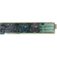
Providing regulated excitation current, the Model 10A15-8 can condition up to eight independent temperature signals from many 3-wire, dual-thermistor-bead probes, in any desired mix (within designated ranges, thermistor probes offer higher accuracy and greater long-term dependability than thermocouples).
All analog input channels derived from a Model 10A15-8 must be given a channel "type" code of 55 ("raw" millivolt signal), via the procedure described in Section 3.a, below.
ADDITIONAL 10A15-8 SPECIFICATIONS
Measurement Range and Resolution: See Table 1, below; automatically selected—on an individual channel basis—when the channel is configured; all 10A15-8 data channels are to be “typed” as “55” (see Section 3.a)
Excitation (per channel): As required for thermolinear transducer
Amplifier (per channel):
Input Impedance: As required for thermolinear transducer
Offset: Initial: ±0.02% of full scale; vs. Temperature: ±50 ppm/°C; vs. Time: ±20 ppm/month
Gain Accuracy: ±0.02% of full scale (absolute maximum input voltage range without damage is ±9 V)
Gain Stability: vs. Temperature: ±50 ppm/°C; vs. Time: ±20 ppm/month
Filter (per channel): 1-pole modified Butterworth; 3 dB down at 30 Hz; 60 dB down at 100 kHz
Step-Response Settling Time (Full-Scale Output):
To 1% of final value: 30 msec
To 0.1% of final value: 60 msec
To 0.02% of final value: 250 msec
Total System Accuracy (typical, including Model 10A15-8, probe interchangeability, and system data collection and processing): see Table 1, below
Auxiliary Outputs to Mainframe Wire-Wrap Pins: None
Table 1 Thermistor Ranges for the Model 10A15-8
| Typical Maximum |
| Display System Expected |
| Range Resolution Accuracy* Error* |
0^ C to +100^ C 0.1^ C ± 0.2^ C ± 0.3^ C
+32°F to +212°F 0.1°F ±0.3°F ±0.5°F
0^ C to +100^ C 0.01^ C ± 0.2^ C ± 0.3^ C
+32°F to +212°F 0.02°F ±0.3°F ±0.5°F
2 TRANSDUCER CONNECTIONS
The Model 10A15-8's I/O CONNECTOR mates with Daytronic CONDITIONER CONNECTOR No. 60322, shown in Fig. 1.5 (in Manual Section 1.E.1). Standard cabling is shown in Fig. 1, below; standard pin assignments for the I/O connector are given in Table 2.

Table 2 Model 10A15-8 Pin Assignments
| I/O Connector Conditioner Conditioner Pin Channel Line Number Number Function | ||
| 1 | 1 | T2 |
| A | 1 | T1 |
| 2 | 2 | |
| B | 2 | T1 |
| 3 | 3 | T2 |
| C | 3 | T1 |
| 4 | 4 | T2 |
| D | 4 | T1 |
| 5 | 5 | T2 |
| E | 5 | T1 |
| 6 | 6 | T2 |
| F | 6 | T1 |
| 7 | 7 | T2 |
| H | 7 | T1 |
| 8 | 8 | T2 |
| J | 8 | T1 |
| 9,K Not Committed | ||
| 10,L SIGNAL COMMON (GROUND) | ||
3 SETUP AND/OR OPERATING CONSIDERATIONS
3.a CONFIGURATION AND CALIBRATION
For initial configuration of ANALOG INPUT CHANNELS dedicated to a specific Model 10A15-8 card, see the general remarks on System 10 "real-channel" configuration in Manual Section 1.G.1 and elsewhere in the System 10 Guidebook.
Note, however, that you should use the following special "typing" and scaling procedure when setting up any data channel (No. "x") dedicated to the Model 10A15-8:
- Turn ON the system EEPROM SWITCH and apply a RESET (RST) command to the channel:
RST x [CR]
The channel will be retyped as "55" (i.e., a direct millivolt reading from the system's internal Called Signal Bus). Its SCALING FACTOR ("m") will be changed to "5000," and its ZERO OFFSET ("b") to "0." Its current "location" (LCT) assignment will not be affected.
- If the channel's source thermistor's range is 0^ to +100^ , and its resolution is 0.1^ , enter the following commands:
$$ \text { EMM } x = 1 0 0. 0 [ \text { CR } ] \quad \text { and } \quad \text { BEE } x = 0. 0 [ \text { CR } ] $$
-or, if the resolution is 0.01^ , enter
$$ \text { EMM } x = 1 0 0. 0 0 [ \text { CR } ] \quad \text { and } \quad \text { BEE } x = 0. 0 0 [ \text { CR } ] $$
- If the channel's source thermistor's range is +32^ to +212^ , and its resolution is 0.1^ , enter the following commands:
$$ \text { EMM } x = 1 8 0. 0 [ \text { CR } ] \quad \text { and } \quad \text { BEE } x = 3 2. 0 [ \text { CR } ] $$
-or, if the resolution is 0.02^ , enter
EMM x = 180.00 [CR] and BEE x = 32.00 [CR]
- Turn OFF the system EEPROM SWITCH.
The Model 10A15-8 normally employs CPU-BASED ABSOLUTE CALIBRATION (described in Manual Section 1.G.3.a). This means that NO calibration need be performed by the user, once each 10A15-8-based input channel has been properly configured. This includes the range/resolution-dependent EMM and BEE scaling described above.
Note, however, that the standard ZERO (ZRO) and FORCE (FRC) commands can be used to perform TWO-POINT (DEADWEIGHT) CALIBRATION in applications where independently and accurately known temperature references are available—preferably the high and low extremes to which the sensor will be subjected. In such a case, the two-point method can be used to improve the “absolute” calibration provided by the System 10 Central Processor. The mainframe’s EEPROM Write Protect Switch must be ON for the ZRO and FRC commands to be effective. See Manual Section 1.G.5 for a general discussion of this conventional “zero and span” calibration technique.



Brand : Daytronic
Model : 10A15-8
Category : Electronic board