10CISO-8 - Electronic board Daytronic - Free user manual and instructions
Find the device manual for free 10CISO-8 Daytronic in PDF.


| Product Type | Data Acquisition System |
| Model | 10CISO-8 |
| Brand | Daytronic |
| Dimensions (H x W x D) | 5.25 x 19.0 x 12.0 inches (133 x 483 x 305 mm) |
| Weight | 10.5 lb (4.8 kg) |
| Power Supply | 100–240 VAC, 50/60 Hz, 50 W max |
| Input Channels | 8 isolated analog inputs |
| Isolation | 1500 V RMS channel-to-channel and channel-to-ground |
| Input Range | ±10 V, 0–10 V, 4–20 mA (selectable) |
| Resolution | 16-bit |
| Sampling Rate | Up to 100 kHz aggregate |
| Communication Interface | Ethernet (TCP/IP), RS-232, USB |
| Operating Temperature | 0°C to 50°C (32°F to 122°F) |
| Storage Temperature | -20°C to 70°C (-4°F to 158°F) |
| Humidity | 5% to 95% non-condensing |
| Mounting | 19-inch rack mount (4U height) |
| Maintenance | Clean with a dry, lint-free cloth. Do not use solvents. |
| Safety | Use only with supplied power cord. Disconnect power before servicing. |
| Spare Parts | Contact Daytronic customer service for replacement modules and accessories. |
| Repairability | Field-replaceable modules. Refer to service manual for detailed procedures. |
| General Information | Designed for industrial data acquisition with high isolation and reliability. |
Frequently Asked Questions - 10CISO-8 Daytronic
User questions about 10CISO-8 Daytronic
0 question about this device. Answer the ones you know or ask your own.
Ask a new question about this device
Download the instructions for your Electronic board in PDF format for free! Find your manual 10CISO-8 - Daytronic and take your electronic device back in hand. On this page are published all the documents necessary for the use of your device. 10CISO-8 by Daytronic.
USER MANUAL 10CISO-8 Daytronic
Special Function "A Cards" & Accessories
Offset: Initial: ±1 mV; vs. Temp.: ±0.25 mV/°C; vs. Time: ±1 mV/month
Gain Accuracy: ±0.02% of full scale
Gain Stability: vs. Temp.: ±50 ppm/°C; vs. Time: ±10 ppm/month
Filter: 3-pole modified Butterworth; 3 dB down at 200 Hz; 60 dB down at 3.4 kHz
Step Response Settling Time (Full-Scale Output):
To 1% of final value: 5 msec
To 0.1% of final value: 7 msec
To 0.02% of final value: 10 msec
Analog Memory Decay Rate: Does not exceed 1 mV/sec
Analog Outputs (per input channel): “+ PEAK” and “- PEAK” available at rear connector; there is no direct “MAX-MIN” analog output. The full-scale amplitude of any given output will be a function of the “TYPE” designation of the respective analog input channel.
Model 10AAO-4 Analog Buffer Card
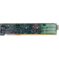
For purposes of “real-time” monitoring, the Model 10AAO-4 provides continuous buffering, filtering, and fixed gain of 1, 2, or 4 for up to four individual System 10 analog signals. Each signal may originate from any one of the system’s Conditioner Cards that provides “Auxiliary Output” to wire-wrap pins.* The actual gain setting for each output will depend on the “TYPE” designation of the corresponding “source” conditioner channel.
Each of the 10AAO-4's four outputs is nominal ±5 V-DC (±6 V maximum), with a minimum load resistance of 2 kΩ. Each output is factory-set for a "single-ended" configuration (i.e., output referenced to Signal Common (Ground)). If desired, however, all four outputs may be reconfigured as "floating," by connecting an external supply of ±9 V-DC, furnished by the user.
Each 10AAO-4 channel contains a 3-pole modified Butterworth filter with a bandwidth of 47 Hz. In addition, individual ZERO and SPAN controls are accessible at the front of the card, for further calibration or scaling of a given channel with reference to its "source" input.
Model 10AAO-8 Analog Output Card
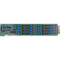
This card provides up to eight independent, digitally-controlled analog output signals that can be used for commanding servo control loops, and for driving external recorders, plotters, indicators, etc. The eight voltage outputs are individually controlled and updated once each scan cycle by the system Central Processor, in accordance with user or computer instructions.
The data source for each 10A0-8 output may be specified as a linear function of any system data channel No. y by applying an ANALOG OUTPUT (ANO) command of
$$ \mathrm{ANO} \mathrm{x} = \mathrm{m} (\mathrm{CHN} \mathrm{y}) + \mathrm{b} $$
where "m" and "b" are floating-point constants entered by the user to convert the engineering units of Channel No. y to millivolts. The allowable range is ± 5000 mV. Alternatively, the data source for an analog output may be specified as a fixed millivolt value.
Additional 10AAO-8 Specifications:
Voltage Signal Output:
Configuration: Single-ended, return to System Common
Range: ±5 volts, with 20% overrange
Resolution: Settable to one millivolt
Allowable Loading: 5 mA, maximum
Accuracy: ±0.05%, ±1 millivolt
Response Time: Output updated once each scan cycle, and processed through 3-pole, 4-Hz active filter (settling time 300 milliseconds) ^*** ; scan cycles per second = 2500/(N + 15), where N is total number of channels
Model 10CISO 8 Isolated Analog Buffer Interface
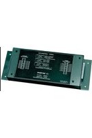
The Model 10CISO-8 is an external unit for ± 10-V isolated buffering of up to eight individual analog signals (with 20% overrange at 1mA and minimum load resistance of 2.5K ). It may be used to amplify the standard ± 5-V analog outputs of a
Model 10AAO-4 or Model 10AAO-8, or of a Conditioner Card that issues such output. A six-foot power cord comes with every unit, with a

natural_image
Exterior view of a black rectangular electronic device with mounting flanges (no visible text or symbols)Model 10CISO-8 (HWD in inches/cm: 1.14/2.90; 9.05/22.99; 3.25/8.26)
switch-selectable transformer that may be plugged into any standard source of 110 or 220 AC.
Common-mode range for the 10CISO-8 is ±50 V, with a rejection ratio of -46 dB at DC and 60 Hz.
Model 10CAI-8 Eight-Channel Buffer Interface
Using this externally mounted buffer unit with the Model 10AAO-4 or Model 10AAO-8, you can directly connect system analog outputs to a test or process that employs TSA standard 4-to-20 mA control signals, or you can amplify analog outputs to the ±10 V-DC range.
Receiving up to eight standard ±5-V inputs from the 10AMO-4 or 10AMO-8, the 10CAI-8 produces up to eight corresponding output signals, each of which is individually programmable for full-scale representation as
- 4 to 20 mA (corresponding to a 10AAO-4 or 10AAO-8 output of 0 to +5 V-DC);
- 4 to 12 to 20 mA (“zero-center,” corresponding to a -5 to +5 V-DC output); or
- ±10 V-DC (corresponding to a -5 to +5 V-DC output).
All 10CAI-8 outputs are "single-ended," and return to Signal Common.
A six-foot power cord comes with every 10CAI-8, with a switch-selectable transformer that may be plugged into any standard source of 110 or 220 V-AC.

natural_image
Electronic component with internal circuitry and mounting brackets (no visible text or symbols)Model 10CAI-8 (HWD in inches/cm: 1.14/2.90; 9.05/22.99; 3.25/8.26)
* Cards without "Auxiliary Output" currently include the Models 10A9-8C, 10A10-4, 10A15-8, 10A35, 10A62-8C, 10A64-8C, 10A65-8, and 10A69-4 (see the latest Conditioner Card Catalog). None of these cards may be directly connected to the Model 10AAO-4 without special modification.
** Higher filter values (1 kHz, 2kHz, or higher) are available on specially modified versions of the 10AAO-8.


- Special Function "A Cards" & Accessories
- Step Response Settling Time (Full-Scale Output):
- Model 10AAO-4 Analog Buffer Card
- Model 10AAO-8 Analog Output Card
- Additional 10AAO-8 Specifications:
- Voltage Signal Output:
- Model 10CISO 8 Isolated Analog Buffer Interface
- Model 10CAI-8 Eight-Channel Buffer Interface
Brand : Daytronic
Model : 10CISO-8
Category : Electronic board