
10A78 - Electronic board Daytronic - Free user manual and instructions
Find the device manual for free 10A78 Daytronic in PDF.

| Product Type | Single-channel phase-sensitive carrier amplifier conditioner for strain gage bridges |
| Brand | Daytronic |
| Model | 10A78 |
| Category | Electronic Board (Conditioner Card) |
| Transducer Types | Conventional 4-arm strain gage bridges, nominal 350 ohms or higher |
| Input Ranges (Full-Scale) | ±0.75, 1.50, or 3.00 mV/V, automatically selected based on channel configuration |
| Excitation | Regulated 3 V-AC (rms) at 3280 Hz; 50 mA (rms) maximum |
| Common-Mode Range | ±1 V operating; ±9 V without damage |
| Common-Mode Rejection Ratio | DC and 60 Hz: infinite; at 3 kHz: -60 dB |
| Input Impedance | 10 MΩ (differential and common-mode) |
| Offset (Initial) | ±3% of full scale |
| Gain Accuracy | ±0.02% of full scale typical (after calibration) |
| Filter | 3-pole modified Butterworth; 3 dB down at 7.5 Hz; 60 dB down at 60 Hz |
| Step-Response Settling Time (Full-Scale Output) | To 1%: 250 ms; to 0.1%: 350 ms; to 0.02%: 500 ms |
| Calibration Resistor (Internal) | 59 kΩ, 0.1% tolerance, user-replaceable |
| Phase and Symmetry Controls | User-adjustable via front-accessible potentiometers |
| Cabling Options | 4-wire (under 20 ft) or 8-wire (20 ft or longer); special Lebow 1600/1800 cabling supported |
| Type Codes (System 10) | 70 (0.75 mV/V), 71 (1.50 mV/V), 72 (3.00 mV/V) |
| Product Manual | 8 pages, English, available for free download in PDF |
| Compatibility | Daytronic System 10 mainframe |
Frequently Asked Questions - 10A78 Daytronic
User questions about 10A78 Daytronic
0 question about this device. Answer the ones you know or ask your own.
Ask a new question about this device
Download the instructions for your Electronic board in PDF format for free! Find your manual 10A78 - Daytronic and take your electronic device back in hand. On this page are published all the documents necessary for the use of your device. 10A78 by Daytronic.
USER MANUAL 10A78 Daytronic
The Model 10A78 is a single-channel conditioner of phase-sensitive carrier-amplifier design (rather than a two-channel, fully DC instrument). Intended for applications involving transformer-coupling to the transducer bridge (as with rotary-transformer torque sensors), this conditioner can also be used in conventional installations when high sensitivity is required or where the electrical environment is especially noisy. Responding only to the modulated carrier frequency, the 10A78 rejects extraneous voltages that can cause errors in DC systems, particularly when there is a need to "blow up" a portion of the transducer range. User-adjustable phase and symmetry controls are provided.
The Model 10A78's data channel is best calibrated by means of a "two-point (dead-weight)" or shunt-calibration technique, following an initial "calculated" calibration. The supplied calibration resistor is 59 kilohms, 1%. Note that the 10A78 can NOT be calibrated via the System 10 MV/V CALIBRATION (MVV) command. Note also that a specially modified version of the 10A78 is required if you wish to control the shunt-calibration process by means of logic-level inputs through the rear I/O CONNECTOR.
ADDITIONAL 10A78 SPECIFICATIONS
Transducer Types: Conventional 4-arm strain gage bridges, nominal 350 ohms (or higher)
Input Ranges (Full-Scale): ±0.75, 1.50, or 3.00 mV/V; automatically selected—on an individual channel basis—when the channel is configured; for the System 10 channel "type" code assigned to a 10A78 data channel, see Table 1, below. Since channel zeroing is by digital techniques, no input balance control is provided. The allowable input range, therefore, must include any initial unbalance (which, in commercially produced strain gage transducers, is usually negligible). Other transducers may have to be externally trimmed to be used with the Model 10A78, if zero unbalance exceeds 20% of full scale.
Excitation: Regulated 3 V-AC (rms) at 3280 Hz; 50 mA (rms), maximum
Amplifier:
Common-Mode Range: ±1 V operating; ±9 V without instrument damage
Common-Mode Rejection Ratio: DC and at 60 Hz: infinite; at 3 kHz: -60 dB
Input Impedance (Differential and Common-Mode): 10 MΩ
Offset: Initial: ±3% of full scale; vs. Temperature: ±0.005% f.s./°C; vs. Time: ±0.02% f.s./month
Gain Accuracy*: ±0.02% of full scale typical, following calibration
(cont'd)
Gain Stability: vs. Temperature: ±50 ppm/°C; vs. Time: ±20 ppm/month
Filter: 3-pole modified Butterworth; 3 dB down at 7.5 Hz; 60 dB down at 60 Hz
Step-Response Settling Time (Full-Scale Output):
To 1% of final value: 250 msec
To 0.1% of final value: 350 msec
To 0.02% of final value: 500 msec
Auxiliary Output: Filtered output available on mainframe wire-wrap pin
Table 1 10A78 "Type" Codes
Full-Scale Channel Input Type Code
| 0.75 mV/V 70 |
| 1.50 mV/V 71 |
| 3.00 mV/V 72 |
2 TRANSDUCER CONNECTIONS
The Model 10A78's I/O CONNECTOR mates with Daytronic CONDITIONER CONNECTOR No. 60322, shown in Fig. 1.5 (in Manual Section 1.E.1). Table 2 gives standard pin assignments for the I/O Connector. With regard to 10A78 cabling, please note the following:
a. 4-wire strain gage cabling is given in Fig. 1(a), and is to be used when the cable is under 20 feet in length. In this case, the +SENSE and -SENSE lines are tied to the corresponding EXCITATION lines (and also the CALIBRATION SENSE line to the +SIGNAL line) at the CONDITIONER CONNECTOR. It is recommended that the resistance of the conductors not exceed 0.0001 of the bridge resistance.
b. 8-wire strain gage cabling is given in Fig. 1(b), and is to be used when the cable is 20 feet or longer, or when fine wire is used.* In this case, the +SENSE and -SENSE lines are tied to the corresponding EXCITATION lines (and also the CALIBRATION SENSE line to the +SIGNAL line) at the transducer. Note also the wire connected to the -SIGNAL line, at the transducer, but left unconnected at the 10A78. This wire is to be paired with the CAL SENSE line for shielding purposes.
NOTE: The special 8-wire cabling shown in Fig. 1(c) is required for connecting a Model 10A78 to a Lebow 1600 Series Transducer. The cable should be shielded in four pairs, as shown, with the shield open at the transducer end. In the case of connection to a Lebow 1600 Series Transducer, also note that
a. SENSE and EXCITATION lines should be tied at the transducer.
b. The 10A78's Pin 5 ("LEBOW CAL") is to be connected to the "CAL" pin on the Lebow sensor (Pin 4 is not used in this case).
c. Leave the last (extra) wire unconnected at both ends, and pair it with the "LEBOW CAL" line for the fourth shield.
d. THE MODEL 10A78 MUST BE INTERNALLY SET TO "SIGNAL COMMON" MODE, via the following procedure:
- Turn OFF mainframe power and remove the 10A78 card from its mainframe slot. For "Card Insertion and Removal," see Manual Section 1.B.
- Refer to Fig. 2, below, and locate the SIGNAL PROGRAMMING JUMPER PADS on the component side of the board.
- The 10A78 is normally shipped with a solder-drop connection between the pair of jumper pads labelled "+S." When the special Lebow 1600 cabling is used, however, the connection between the "+S" pads should be removed, and a solder-drop connection should be made between the pair of jumper pads labelled "S.C."
(cont'd)
Fig. 1 Model 10A78 Transducer Cabling


Fig. 1(b) 8-Wire Strain Gage Cabling (20 ft. or longer)

Fig. 1(c) 8-Wire Cabling to Lebow 1600 Series Transducer (ONLY)
To "unblob" the "+S" jumpers, use a fine-point solder gun to heat the solder drop, until it has melted sufficiently for you to wipe it off with a clean rag. Make sure that you remove all traces of solder from the jumper pads you wish to "unblob."
- Reinsert the 10A78 card in its mainframe slot and reactivate mainframe power.
Table 2 Model 10A78 Pin Assignments
| I/O Connector ConditionerPin LineNumber Function | ||
| 1 +EXCITATION (3 V-AC)A -EXCITATION (3 V-AC)2 +SENSEB -SENSE3 +SIGNALC -SIGNAL4 C AL SENSED SIGNAL COMMON5 LEBOW CALAll Other Pins Not Committed | ||
Fig. 2 10A78 Signal Programming Jumper Pads and Shunt Calibration Resistor

3 SETUP AND/OR OPERATING CONSIDERATIONS
3.a PHASE AND SYMMETRY ADJUSTMENT FOR ALL TRANSDUCERS EXCEPT A LEBOW 1800 SERIES TRANSDUCER
Before you do a "two-point" or "shunt" calibration of your 10A78 for the first time, you should perform an initial "on-line" phase and symmetry adjustment. When using a Lebow 1800 Series Transducer (only), you should follow the special procedure given in the next section. For any other transducer, use the following procedure. ONCE SET FOR YOUR TRANSDUCER, THIS ADJUSTMENT NEED NOT BE REPEATED UNLESS A SIGNIFICANT CHANGE IN CABLE LENGTH OR CAPACITANCE IS REQUIRED.
a. Turn ON the system EEPROM Switch and enter a command of
SCALING FACTOR (EMM)
$$ \mathbf {E M M} \mathbf {x} = \mathbf {m} [ \mathbf {C R} ] $$
where "x" is the Channel Number of the 10A78's measurement channel, and "m" is the full-scale input range in the desired engineering units and with the desired resolution.
b. Provide a "live" display of the data reported by Channel No. x.
c. Without removing the 10A78 from its slot, locate the PHASE AND SYMMETRY CONTROLS, which are accessible from the front of the card (see Fig. 3).
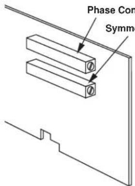
Fig. 3 10A78 Phase and Symmetry Controls
d. Load the transducer in the positive direction with a convenient "deadweight" value which is greater than one-half of full scale. Using a small insulated screwdriver, adjust the 10A78's PHASE CONTROL until a maximum reading is obtained for the 10A78 channel.
e. Remove the transducer load.
f. Make sure the system EEPROM Switch is still ON and enter a ZERO (ZRO) command of
ZRO x [CR]
g. Now switch in the 10A78's internal shunt resistor for a positive up-scale reading by entering a command of
SHP x [CR]
h. Record the reading you get.
i. Open the positive shunt and switch in the resistor for a negative reading by entering a command of
SHN x [CR]
j. Adjust the 10A78's SYMMETRY CONTROL until the negative value of the reading you recorded in Step h appears.
k. Open the negative shunt by entering a command of
RSM x [CR]
I. You are now ready to perform "on-line calibration" of the 10A78 channel by either the "Two-Point (Deadweight)" or "Simulated (Shunt)" Calibration method (see Section 3.c, below).
3.b PHASE AND SYMMETRY ADJUSTMENT FOR A LEBOW 1800 SERIES TRANSDUCER
NOTE: WHEN USING THE 10A78 WITH A LEBOW 1800 SERIES TRANSDUCER, YOU SHOULD FIRST REPLACE THE 10A78'S INTERNAL 59K SHUNT RESISTOR WITH THE CALIBRATION RESISTOR SUPPLIED WITH THE TRANSDUCER.
a. Locate the "CAL/RUN" Switch in the cable harness of the 1800 Series transducer. Place this switch in the "CAL" position.
b. Perform Steps a through c of the above procedure (Section 3.a).
c. Establish a zero input for the 10A78 channel by removing all load from the 1800 Series transducer.
d. Switch in the 10A78's internal shunt resistor for a positive up-scale reading by entering a command of
SHP x [CR]
e. Using a small insulated screwdriver, adjust the 10A78's PHASE CONTROL until a maximum reading is obtained for the channel.
f. Open the positive shunt by entering a command of
RSM x [CR]
g. Make sure the EEPROM Switch is still ON, and zero the reading of the 10A78 channel by entering a command of
ZRO x [CR]
h. Close the channel's positive shunt once more via the SHP command, as in Step d, above.
i. You will now "force" the 10A78 channel to read the "EQUIVALENT INPUT" VALUE GIVEN BY THE TRANSDUCER MANUFACTURER FOR THE CALIBRATION RESISTOR YOU INSTALLED IN THE 10A78 (for a general discussion of EQUIVALENT INPUT, see Section 3.c, below, and Manual Section 1.G.7). Enter a FORCE (FRC) command of
FRC x = z [CR]
where "z" is the equivalent input expressed in the desired engineering units.
j. Open the positive shunt and switch in the resistor for a negative reading by entering a command of
SHN x [CR]
k. Adjust the 10A78's SYMMETRY CONTROL to display the negative value of the same EQUIVALENT INPUT you entered in Step i (or some other specific negative engineering-unit value, if such a value is given by the transducer manufacturer for the calibration resistor).
I. Open the negative shunt by entering a command of
RSM x [CR]
m. Move the transducer's "CAL/RUN" Switch to the "RUN" position.
n. Zero the 10A78 channel's reading once more, as you did in Step g, above.
THE LEBOW 1800 / DAYTRONIC 10A78 SYSTEM IS NOW FULLY CALIBRATED. YOU NEED NOT PERFORM A SUBSEQUENT "DEADWEIGHT" OR "SIMULATED" CALIBRATION.
3.c CONFIGURATION AND CALIBRATION
For initial configuration of the ANALOG INPUT CHANNEL dedicated to a specific Model 10A78 card when used in System 10, see the general remarks on System 10 "real-channel" configuration in Manual Section 1.G.1 and elsewhere in the System 10 Guidebook. For 10A78 channel "type" codes, see Table 1, above.
In System 10, you can use two calibration methods with the Model 10A78 (note that this conditioner cannot be calibrated by the "MVV-CALCULATED" CALIBRATION technique that may be applied to other Strain Gage Conditioner Cards):
Two-Point (Deadweight) Calibration
Using the standard ZERO (ZRO) and FORCE (FRC) commands, this conventional "zero and span" method can easily be applied to a 10A78 channel. The mainframe's EEPROM Write Protect Switch must be ON for the ZRO and FRC commands to be effective. See Manual Section 1.G.5 for a general discussion of this calibration technique.
SIMULATED (SHUNT) CALIBRATION
This method is similar to the conventional TWO-POINT (DEADWEIGHT) procedure. The difference is that the second (“span”) input is not produced by loading the source transducer, but by “simulating” a particular up-scale value of mechanical input. This known EQUIVALENT INPUT then serves to determine the SCALING FACTOR for the channel.
For the 10A78's data channel, the equivalent input is produced by shunting a resistor of known magnitude across one arm of the strain gage bridge, thereby simulating a known value of input for either a positive or negative up-scale reading. If the transducer manufacturer has supplied the exact value of the transducer's equivalent input, it can be used as a reference point for calibrating the channel.
Equivalent input can be approximated from a knowledge of the Shunt Calibration Resistance (R), the transducer's Bridge Resistance (B), and the transducer's Full-Scale Sensitivity (K, in mV/V full scale). To determine the EQUIVALENT INPUT (X) as an approximate percentage of full-scale output, you may use the following equation:
$$ \mathrm{X} = 25000 \mathrm{B} / \mathrm{K} (\mathrm{R} + 0.5 \mathrm{B}) \% $$
Since the equivalent input is here expressed as a percentage of full-scale output, you must multiply it by the rated full-scale capacity of the transducer, in order to determine the actual input simulated by the shunt.
Shunt calibration is an easier though generally less accurate technique then two-point (deadweight) calibration. It is useful, however, when overall “deadweighting” is impossible or inconvenient, and is good for an accuracy of about 0.2% (depending, of course, on the accuracy of the specified equivalent input, and on the resistor/bridge tolerance and temperature).
The 10A78 is equipped with a 59-kΩ, 0.1% calibration resistor, located on turret terminals at the rear of the card (see Fig. 2). You may, if you wish, replace the installed 59K shunt resistor with a resistor of another value (strain-gage transducer manufacturers often supply such resistors with their instruments).
In System 10, a strain gage channel's shunt resistor may be switched in and out by means of the SHUNT CALIBRATE-POSITIVE (SHP) or SHUNT CALIBRATE-NEGATIVE (SHN) command. A RESUME (RSM) command should then be applied to remove the shunt and resume normal channel measurement. Since these are "runtime" commands, the mainframe's EEPROM Write Protect Switch need not be on for them to be effective. See Manual Section 1.G.6 for general instructions regarding the "SHUNT CALIBRATION" technique in System 10.
NOTE: If you wish to control the shunt calibration process by means of logic-level inputs through the 10A78's rear I/O CONNECTOR—a standard feature of other strain gage conditioner cards—you will require a specially modified version of the 10A78.


- ADDITIONAL 10A78 SPECIFICATIONS
- Amplifier:
- Step-Response Settling Time (Full-Scale Output):
- TRANSDUCER CONNECTIONS
- SETUP AND/OR OPERATING CONSIDERATIONS
- 3.a PHASE AND SYMMETRY ADJUSTMENT FOR ALL TRANSDUCERS EXCEPT A LEBOW 1800 SERIES TRANSDUCER
- 3.b PHASE AND SYMMETRY ADJUSTMENT FOR A LEBOW 1800 SERIES TRANSDUCER
- ZRO x [CR]
- FRC x = z [CR]
- SHN x [CR]
- RSM x [CR]
- 3.c CONFIGURATION AND CALIBRATION
- Two-Point (Deadweight) Calibration
- SIMULATED (SHUNT) CALIBRATION
Brand : Daytronic
Model : 10A78
Category : Electronic board