
DS-3E7806 - Network switch Hikvision - Free user manual and instructions
Find the device manual for free DS-3E7806 Hikvision in PDF.


| Product Type | Network Switch |
| Model | DS-3E7806 |
| Brand | Hikvision |
| Ports | 8 x 10/100/1000Base-T + 2 x SFP |
| Switching Capacity | 20 Gbps |
| Packet Forwarding Rate | 14.88 Mpps |
| MAC Address Table | 8K entries |
| Dimensions (W x D x H) | 440 mm x 200 mm x 44 mm |
| Weight | 3.5 kg |
| Power Supply | AC 100-240V, 50/60Hz |
| Power Consumption | ≤ 20W |
| PoE Support | No (non-PoE model) |
| Management | Web, CLI, SNMP, RMON |
| VLAN | 802.1Q VLAN, up to 4K |
| Quality of Service | 802.1p, DSCP |
| Security | ACL, 802.1X, Port Security |
| Mounting | Rack-mountable (1U) |
| Operating Temperature | 0°C to 45°C |
| Storage Temperature | -20°C to 70°C |
| Humidity | 5% to 95% (non-condensing) |
| Maintenance | Clean with soft dry cloth; avoid liquids |
| Safety Instructions | Read manual before use; keep away from water |
| Spare Parts | Not user-replaceable; contact support |
| General Information | Designed for small to medium networks |
Frequently Asked Questions - DS-3E7806 Hikvision
User questions about DS-3E7806 Hikvision
0 question about this device. Answer the ones you know or ask your own.
Ask a new question about this device
Download the instructions for your Network switch in PDF format for free! Find your manual DS-3E7806 - Hikvision and take your electronic device back in hand. On this page are published all the documents necessary for the use of your device. DS-3E7806 by Hikvision.
USER MANUAL DS-3E7806 Hikvision
HIKVISION DS-3E7800 Switch Series Installation Quick Start-AP100
BOM:3104A15E

- This document provides a brief guide for installing HKVISION DS-3E7800 switch series. For more installation information, see HKVISION DS-3E7800 Switch Series Installation Guide.
• The figures in this document are for illustration only. - The installation procedure is similar for the DS-3E7800 switches. The following uses an DS-3E7806 switch as an example unless otherwise specified
Safety recommendations
To avoid equipment damage or bodily injury, read the following safety recommendations before installation. Note that the recommendations do not cover every possible hazardous condition.

• To prevent ESD damage, always wear an ESD wrist strap and make sure it is reliably grounded before you touch the switch, cards, or PCB.
- Do not install the switch FRUs, or cables when the switch is powered on.
- To avoid equipment damage or bodily injury, make sure the switch is reliably grounded before powering on the switch.
Tool list

Prepare the following installation tools yourself as required.

Flat-blade screwdriver

Philips screwdriver

Needle-nose
pliers

Diagonal pliers

Marker

Wire-stripping plers

Claw hammer
Installation accessories

This section only lists the most commonly used installation accessories.
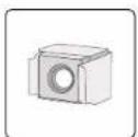
Floating nut
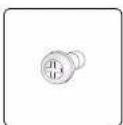
M6 screw
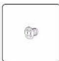
M4 counter-
sunk-head screw
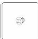
M3 counter-
sunk-head screw
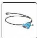
Console cable
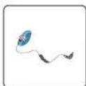
ESD wrist strap
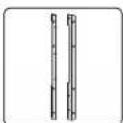
Mounting brackets
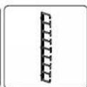
Cable management bracket
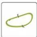
Grounding cable
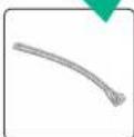
Removable cable tie
Installing the switch
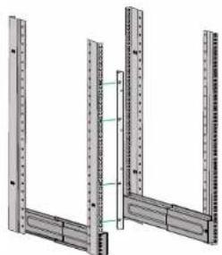
Attaching cage nuts to the rack
natural_image
Technical diagram of a structural frame with vertical and horizontal metal bars (no text or symbols)- Determine the cage nut installation holes based on the mounting bracket and side rail installation positions
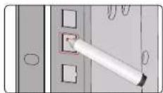
2. Mark the cage nut installation holes
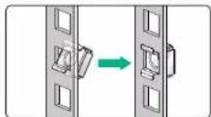
3. install cage nuts.
Installing cable management brackets
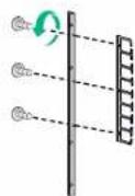
Attach the cable management bracket to the left mounting bracket, which has installation holes for the cable management bracket.
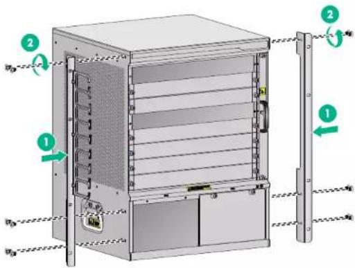
Installing mounting brackets
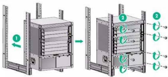
Installing the switch in a rack

Use a minimum of two people to move the switch. For heavy models, use a mechanical lift as a best practice.

- Do not try to move the chassis by holding an FRU handle, air vents of chassis, or the handle on the rear. Any attempt to carry the switch with these parts might cause equipment damage or even bodily injury.
• After placing the switch on the slide rails, do not leave go of your hands immediately because this might to the switch. Tipping the switch might cause switch damage and even bodily injury.
3
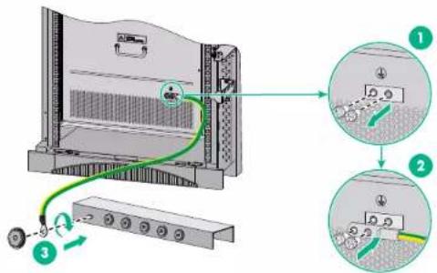
Grounding the switch

To ensure the grounding effect, use the yellow-green grounding cable provided with the switch to ground the switch

Connect the grounding cable to the grounding system in the equipment room. Do not connect it to a fire main or lightning rod.
Installing FRUs
Installing cards

Before installing a card in the chassis, make sure the connectors on the card are not broken or blocked.
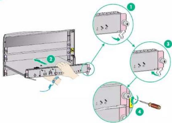
4
Installing power modules
- For dual-grid input, the input voltage, phase, and frequency for the two grids must be the same.
- To use two power modules, provide a circuit breaker for each power module.
• Do not install power modules of different models on the same switch. - To avoid power module damage or bodily injury, move a power module by supporting its bottom instead of holding its handle.
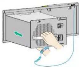
natural_image
Illustration of a hand inserting a device into a rack-mounted unit with a green arrow indicating direction (no text or symbols)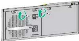
Connecting power cords
- Before connecting an AC power cord, make sure the circuit breaker at the power source end is turned off.
- Before connecting a DC power cord, make sure the circuit breakers for the positive (+) and negative (−) terminals at the power source end are switched off.
Connecting the power cord for a PSR650C-12Apower module
The PSR650C-12A power module uses a 10A AC power cord
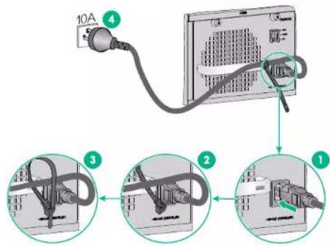
5
Connecting the power cord for a PSR650C-12D power module
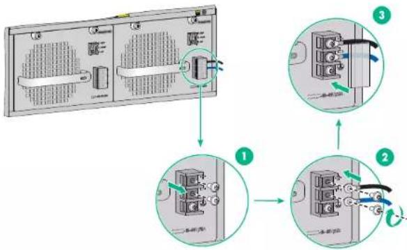
flowchart
graph TD
    A[" fan "] --> B[" component 1 "]
    B --> C[" component 2 "]
    C --> D[" component 3 "]
    D --> E[" final panel with arrow indicating rotation"]
Accessing the switch
Connecting the console cable
To access the switch for the first time, use a console cable to connect the console port or USB console port on the switch. If you connect both the console port and USB console port, only the USB console port is available.
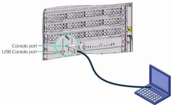
6
Powering on the switch and verifying its operation
Make sure the power cords are connected correctly and the power source is operating correctly. Then power on the switch. Verify that the switch is operating correctly by observing the LEDs on the switch. For more information about the LEDs, see HKVISION DS-3E7800 Switch Series Hardware Information and Specifications.
COPYRIGHT © 2022 Hangzhou Hikvision Digital Technology Co., Ltd.
For more information about the product and installation procedures, go to http://overseas.hikvision.com/en/
- HIKVISION DS-3E7800 Switch Series Installation Quick Start-AP100
- Safety recommendations
- Tool list
- Installation accessories
- Installing the switch
- Installing cable management brackets
- Installing power modules
- Connecting power cords
- Connecting the power cord for a PSR650C-12Apower module
- Connecting the power cord for a PSR650C-12D power module
- Accessing the switch
- Connecting the console cable
- Powering on the switch and verifying its operation
Brand : Hikvision
Model : DS-3E7806
Category : Network switch