
PowerSwitch S6100-ON - Network switch DELL - Free user manual and instructions
Find the device manual for free PowerSwitch S6100-ON DELL in PDF.


| Product Type | Network Switch |
| Brand | Dell |
| Model | PowerSwitch S6100-ON |
| Form Factor | 1U Rackmount |
| Dimensions (W x D x H) | 17.3 x 20.5 x 1.73 inches |
| Weight | 15.9 kg |
| Power Supply | AC 100-240V, 50/60Hz, Dual hot-swappable PSUs |
| Power Consumption (Typical) | 350 W |
| Ports | 48 x 10GbE SFP+ and 6 x 40GbE QSFP+ |
| Switching Capacity | 1.76 Tbps |
| Forwarding Rate | 1095 Mpps |
| Operating System | Dell Networking OS (DNOS) / ONIE |
| VLAN Support | Yes, up to 4096 VLANs |
| Security Features | ACL, 802.1X, RADIUS, TACACS+ |
| Management | CLI, SNMP v1/v2/v3, Web GUI, REST API |
| Cooling | Front-to-back airflow, hot-swappable fans |
| Spare Parts & Repairability | Hot-swappable PSUs and fan modules; optional on-site service |
| Cleaning Instructions | Disconnect power, use dry cloth only; avoid liquids |
| Safety Certifications | CE, FCC, UL, VCCI |
| Operating Temperature | 0°C to 45°C (32°F to 113°F) |
Frequently Asked Questions - PowerSwitch S6100-ON DELL
User questions about PowerSwitch S6100-ON DELL
0 question about this device. Answer the ones you know or ask your own.
Ask a new question about this device
Download the instructions for your Network switch in PDF format for free! Find your manual PowerSwitch S6100-ON - DELL and take your electronic device back in hand. On this page are published all the documents necessary for the use of your device. PowerSwitch S6100-ON by DELL.
USER MANUAL PowerSwitch S6100-ON DELL
Dell EMC PowerSwitch S6100-ON Installation Guide
March 2021
Notes, cautions, and warnings
NOTE: A NOTE indicates important information that helps you make better use of your computer.
CAUTION: A CAUTION indicates either potential damage to hardware or loss of data and tells you how to avoid the problem.
WARNING: A WARNING indicates a potential for property damage, personal injury, or death.
Contents
Chapter 1: About this guide....5
Notices....5
Related documents....5
Chapter 2: S6100-ON system....6
Introduction......6
Features....7
Physical dimensions....8
Luggage tag....8
System status....9
LED display....9
LED behavior 9
Prerequisites....11
S6100-ON configurations.... 11
Chapter 3: Site preparations....12
Site selection....12
Cabinet placement....12
Rack mounting....13
System ground....13
Fans and airflow....13
Power....13
Storing components....13
Chapter 4: NEBS compliance.... 15
Important information....15
NEBS-compliant ground installation....15
For rack spans from 22 to 23.375 inches....16
For rack spans from 23.375 to 36 inches....18
Chapter 5: S6100-ON installation....21
Installation overview....21
Unpack the S6100-ON System....21
Four-post rack assembly....22
Four-post rack mount....22
Chassis ground....23
I/O module installation....25
Important points....25
SFP+ and QSFP optics installation....26
SFP+ and QSFP optics removal....26
Port connectivity....26
System power-up....28
Chapter 6: Power supplies....29
Components....29
AC or DC power supply installation.... 30
DC power supply connection....31
AC or DC power supply replacement....32
Chapter 7: Fans....33
Components.... 33
Fan module installation....34
Fan module replacement.... 34
Fan air filter replacement....35
After system installation....35
Chapter 8: Management ports....36
RS-232 console port access....36
Accessing the RJ-45 Console Port with a DB-9 Adapter....37
Micro USB-B console port access.... 37
USB storage....37
Before you install an OS....38
ONIE service discovery....39
Chapter 9: Dell support....41
Chapter 10: Specifications....43
Chassis physical design....43
IEEE standards....44
Agency compliance....45
USA Federal Communications Commission (FCC) statement....45
European Union EMC Directive Conformance statement....45
Japan: VCCI Compliance for Class A Equipment....46
Korean Certification of Compliance....46
Safety Standards and Compliance Agency Certifications....47
Electromagnetic Compatibility (EMC)....47
Product recycling and disposal....48
About this guide
This guide provides site preparation recommendations, step-by-step procedures for rack mounting and desk mounting, inserting optional modules, and connecting to a power source.
Topics:
- Notices
•Related documents
Notices

CAUTION: To avoid electrostatic discharge (ESD) damage, wear grounding wrist straps when handling this equipment.

NOTE: Only trained and qualified personnel can install this equipment. Read this guide before you install and power up this equipment. This equipment contains two power cords. Disconnect both power cords before servicing.

NOTE: This equipment contains optical transceivers, which comply with the limits of Class 1 laser radiation.

Figure 1. Class 1 Laser Product Tag

NOTE: When no cable is connected, visible and invisible laser radiation may be emitted from the aperture of the optical transceiver ports. Avoid exposure to laser radiation and do not stare into open apertures.
Related documents
For more information about the S6100-ON system, see the following documents:
●Dell Getting Started Guide for the S6100-ON System
●Dell Release Notes for the S6100-ON System
- Open Networking (ON) Hardware Diagnostic Guide
●Dell Command Line Reference Guide for the S6100-ON System
- Dell Configuration Guide for the S6100-ON System

NOTE: For the most recent documentation, visit Dell Support: www.dell.com/support.
S6100-ON system
The following sections describe the Dell S6100-ON system:
Topics:
- Introduction
- Features
•Physical dimensions
• Luggage tag - System status
- LED display
•Prerequisites
•S6100-ON configurations
Introduction
S6100-ON is a two rack unit 10/25/40/100 GbE switch. A fully loaded system includes 64 quad form-factor pluggable (QSFP+ or QSFP28) optics for 40/100 GbE aggregation and 10/25/40/100 GbE top of rack (ToR) and end of row (EoR) applications.
The S6100-ON system includes two hot-swappable AC or DC power supply units (PSUs) and four hot-swappable fan units.
The S6100-ON supports three types of I/O modules:
- 16 x 40 GbE QSFP+
- Top row of ports can operate as:
■ Single 40G port
Quad 10G ports
NOTE: If you configure port [n] as a quad 10G port, port [n + 1] will not be available
- 8 x 100 GbE QSFP28
○Each port can operate as:
■ Single 100G port
■ Single 40G port
Quad 25G ports
Quad 10G ports
- 4 x QSFP28 + 4 x CXP
○Each QSFP28 port can operate as:
■ Single 100G port
■ Single 40G port
Quad 25G ports
Quad 10G ports
○Each CXP port can operate as:
■ Single 100G port
All 100 GbE (QSFP28) ports support 4 x 25 GbE.
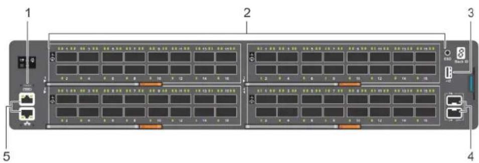
Figure 2. S6100-ON I/O-side view
- MicroUSB-B port 2. 64 x 10/40 QSFP+ or 32 x 10/25/40/100 QSFP28
- USB Type A 4. SFP+ ports
- Top: RJ-45 console port. Bottom: RJ-45 management port

Figure 3. S6100-ON PSU-side view
- Fan modules
- Power supply units
Features
The S6100-ON offers the following features:
- Up to four I/O modules of 8 x 10/25/40/50/100 GbE QSFP28 ports
- Up to four I/O modules of 16 x 10/40 GbE QSFP+ ports
- Up to four I/O modules of 4 x 10/25/40/50/100 GbE QSFP28 ports and 4 x 100 GbE CXP ports
- Up to one hundred twenty-eight 10G ports
●Up to one hundred twenty-eight 25G ports - Up to sixty-four 40G ports
●Up to sixty-four 50G ports - Up to thirty-two 100G ports
- Two SFP+ ports
●One micro universal serial bus (MicroUSB-B) console port, optional
●One 2.0 USB Type-A port for additional file storage
●One 10/100/1000BaseT Ethernet management port - Rangeley central processing unit (CPU) system with 8GB DDR III RAM.
-
Temperature monitoring
●Software-readable thermal monitor
●Real time clock (RTC) support
●Hot-pluggable redundant power supplies
●Power management monitoring
●Four hot-pluggable replaceable fan modules -
Standard 2U chassis
- Two-hole ground lug
Physical dimensions
The S6100-ON has the following physical dimensions:
- 442 x 510 x 86.75 mm (W x D x H)
- 17.40 x 20 x 3.41 inches (W x D x H)
Luggage tag
The S6100-ON system has a pull-out tag, known as a luggage tag, on the I/O-side of the system.

Figure 4. S6100-ON luggage tag
-
Service tag 2. PPID
-
MAC address 4. Express service code
System status
You can view S6100-ON status information using the LEDs.
LED display
The S6100-ON includes LED displays on the I/O side of the system.

NOTE: If you are installing third-party software, for LED information, see your third-party operating software documentation.
LED behavior
The following S6100-ON system LED behavior is seen during open networking installation environment (ONIE) operations:
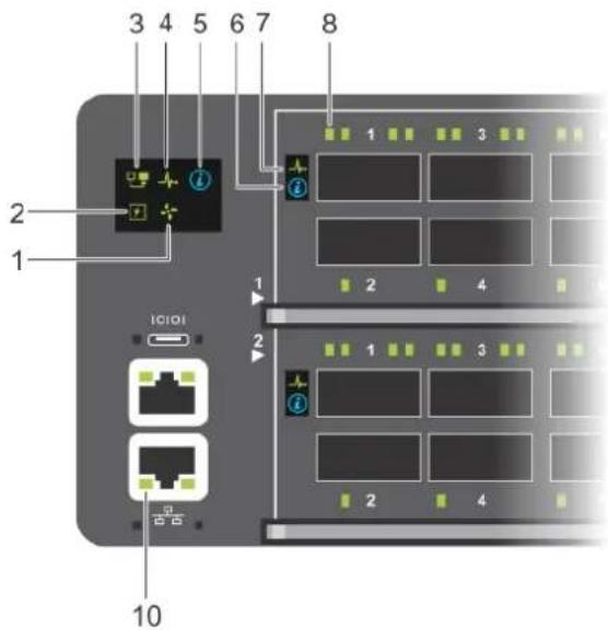
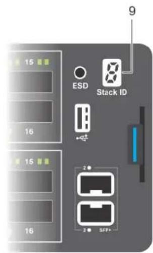
Figure 5. S6100-ON LEDs
- Fan LED 2. Power LED
- Master LED 4. System LED
- Locator LED 6. Locator LED
- System LED 8. Port LEDs
- Stack ID LED 10. RJ-45 Ethernet Management Port LED
Table 1. S6100-ON LED behavior
| LED Description | |
| System Status and Health LED | ●Off—No power●Solid green—Normal Operation●Blinking green—POST is in process●Solid amber—Critical system error●Blinking amber—Minor system error |
| Power LED | ●Off—No power●Solid green—Normal Operation●Solid amber—POST is in process●Blinking amber—Noncritical system error—power supply failure |
| Master LED | ●Off—Switch is in Stacking Slave mode●Solid green—System is in Stacking Master or Standalone mode |
| Management LED | ●Off—No Link●Solid green—Link on 1 Gbps speed●Solid amber—Link on 10/100 Mbps speeds●Blinking green—Port activity |
| FAN LED | ●Off—No power●Solid green—fan powered and running at the expected RPM●Blinking amber—fan failed, including incompatible airflow direction when you insert the PSU or fan trays with differing airflows |
| LOCATOR LED | ●Off—Locator is idle●Blinking blue—Locator is functioning |
Table 2. QSFP28 port LEDs
| LED Description | |
| Link LED | ●Off—No Link●Solid green—Port activity operating at maximum port speed●Solid amber—Port activity operating at lower speed |
| Activity LED | ●Off—No Link●Flashing green, ~30 ms—port activity operating at maximum port speed●Flashing amber, ~30 ms—port activity operating at lower port speed |
Table 3. QSFP28 port LEDs—4x25 GbE or 4x10 GbE Mode
| LED Description | |
| Link LED | ●Off—No Link●Solid green—Port link is 4x25 GbE●Solid amber—Port link is 4x10 GbE |
| Activity LED | ●Off—No Link●Flashing green, ~30 ms—Port link is 4x25 GbE●Flashing amber, ~30 ms—Port link is 4x10 GbE |
Table 4. QSFP28 Port LEDs—2x40GbE Mode
| LED Description | |
| Link LED | ●Off—No Link●Solid green—Port link is 2x40 GbE |
| Activity LED | ●Off—No Link●Flashing amber, ~30 ms—Port link is 2x40 GbE |
Table 5. SFP+ port LEDs
| LED Description | |
| Link LED | ●Off—No Link●Solid green—Port activity operating at maximum port speed●Solid amber—Port activity operating at lower speed |
| Activity LED | ●Off—No Link●Flashing green, ~30 ms—port activity operating at maximum port speed●Flashing amber, ~30 ms—port activity operating at lower port speed |
Prerequisites
The following is a list of components required for successful installation of the S6100-ON:
NOTE: Detailed installation instructions for the S6100-ON are provided in Site preparations and S6100-ON Installation.
●S6100-ON chassis or multiple chassis, if stacking
- AC or DC country and regional-specific cables to connect the AC or DC power source to each of the chassis' AC or DC power supplies
●Mounting brackets for rack installation, included
●Screws for rack installation
- #1 and #2 Phillips screw drivers, not included
●Torx screwdriver, not included
●Ground cable screws, included
●Copper or fiber cables
Other optional components are:
●Ground cable
- Extra power supply unit
- Extra fan module
- Extra mounting brackets
S6100-ON configurations
You can order the S6100-ON system in several different configurations.
- S6100–ON AC or DC Normal Airflow: thirty-two 10/25/40/100 GbE ports with four SFP+ 10 GbE ports, two AC or DC power supply units and four fan subsystems. Fan airflow is from the I/O side to the power supply side.
- S6100–ON AC or DC Reverse Airflow: thirty-two 10/25/40/100 GbE ports with four SFP+ 10 GbE ports, two AC or DC power supply units and four fan subsystems. Fan airflow is from the I/O side to the power supply side.
●Fan with airflow from the I/O side to the PSU side.
●Fan with airflow from the PSU side to the I/O side.
- AC or DC power supply with airflow from the I/O side to the PSU side.
- AC or DC power supply with airflow from the PSU side to the I/O side.
The S6100-ON offers three types of I/O modules:
- 16 x 40 GbE QSFP+
- 8 x 100 GbE QSFP28
- 4 x QSFP28 + 4 x CXP
Site preparations
The S6100-ON is suitable for installation as part of a common bond network (CBN).
You can install the system in:
●Network telecommunication facilities
- Data centers
●Other locations where the National Electric Code (NEC) applies
For more information about S6100–ON specifications, see Specifications.

NOTE: Install the S6100-ON system into a rack before installing any optional components.
Topics:
- Site selection
•Cabinet placement - Rack mounting
- System ground
•Fans and airflow
•Power - Storing components
Site selection
Install Dell equipment in restricted access areas.
A restricted access area is one in which service personnel can only gain access using a special tool, lock, key or other means of security. Access is controlled by the authority responsible for the location.
Ensure that the area where you install your S6100-ON system meets the following safety requirements:
- Near an adequate power source. Connect the system to the appropriate branch circuit protection as defined by your local electrical codes.
●Environmental temperature range is from 32° to 113°F (from 0° to 45°C). - The switch operating ambient temperature range is from 10^ to 35^ (from 50^ to 95^ ).
●Relative humidity is from 5 to 85 percent noncondensing. - In a dry, clean, well-ventilated and temperature-controlled room, away from heat sources such as hot air vents or direct sunlight.
● Away from sources of severe electromagnetic noise. - Positioned in a rack or cabinet, or on a desktop with adequate space in the front, back, and sides for proper ventilation and access.
Cabinet placement
Install the S6100-ON only in indoor cabinets designed for use in a controlled environment.
Do not install the S6100-ON in outside cabinets. For cabinet placement requirements, see Site selection.
The cabinet must meet minimum size requirements. Airflow must be in accordance with the Electronic Industries Alliance (EIA) standard. Ensure that there is a minimum of 5 inches (12.7 cm) between the intake and exhaust vents and the cabinet wall.
Rack mounting
When you prepare your equipment rack, ensure that the rack is grounded.
Ground the equipment rack to the same ground point the power service in your area uses. The ground path must be permanent.
System ground
Dell recommends grounding your system. Use the S6100–ON in a common bond network (CBN).
Connect the grounding cables as described in S6100-ON installation.
Fans and airflow
The S6100-ON fans support two airflow options: normal and reverse.
Fan combinations
The S6100-ON has stock keeping units (SKUs) that support the following configurations. Installation of the fans is done as part of the factory install based on SKU type.
●AC or DC PSU with fan airflow from the I/O to the PSU
- AC or DC PSU with fan airflow from the PSU to the I/O
Be sure to order the fans suitable to support your site's ventilation. Use a single type of airflow fan in your system. Do not mix reverse and normal airflows in a single S6100–ON chassis.
For proper ventilation, position the S6100-ON in an equipment rack or cabinet with a minimum of 5 inches (12.7 cm) of clearance around the exhaust vents. When you install two S6100-ON systems near each other, to permit proper airflow, position the two chassis at least 5 inches (12.7 cm) apart. The fan speed increases when the internal temperature reaches 161.6°F (72°C). The fan speed decreases to normal speed when the temperature falls to 136.4°F (58°C). The S6100-ON never intentionally turns off the fans.
Power
To connect the chassis to the applicable power source, use the appropriate power cord with the S6100-ON. An AC or DC power cord is included with the system.
When installing AC or DC systems, follow the requirements of the National Electrical Code, ANSI/NFPA 70 where applicable.
CAUTION: Always disconnect the power cable before you service the power supply slots.
CAUTION: Use the power supply cord as the main disconnect device on the AC system. Ensure that the socket-outlet is located and installed near the equipment and is easily accessible.
The system is powered-up when the power cord is connected between the system and the power source.
NOTE: Module power is software controlled. You do not see module LEDs when the system powers up in ONIE.
Storing components
If you do not install your S6100-ON and components immediately, properly store the system and all optional components by following these guidelines:
- Storage location temperature must remain constant. The storage range is from -40^ to 158^ (-40°C to 70°C).
- Store on a dry surface or floor, away from direct sunlight, heat, and air conditioning ducts.
- Store in a dust-free environment.

NOTE: ESD damage can occur when components are mishandled. Always wear an ESD-preventive wrist or heel ground strap when handling the S6100-ON and its accessories. After you remove the original packaging, place the S6100-ON and its components on an anti-static surface.
NEBS compliance
For your system to be network equipment building system (NEBS) compliant, you must follow the instructions detailed in this chapter.
To be NEBS-compliant, orient your system in the rack so that the air inlet is from the front aisle and the air exhaust is to the rear aisle.
Topics:
- Important information
•NEBS-compliant ground installation
Important information
WARNING: The quad form-factor pluggable (QSFP), console, Ethernet management, and universal serial bus (USB) ports are suitable for connection to intra-building or unexposed wiring or cabling only. You MUST NOT metallically connect the ports to interfaces that connect to the out side plant (OSP) or its wiring. Use these interfaces as intra-building interfaces only (Type 2 or Type 4 ports as described in GR-1089-CORE, Issue 6) and they require isolation from the exposed OSP cabling. Adding primary protectors is not sufficient protection to connect these interfaces metallicly to OSP wiring.
WARNING: If you install and connect the S6100-ON to a commercial AC power source, you must connect the system to an external special protection device (SPD).
To be NEBS-compliant, you must follow these regulations:
- Locate your system in a restricted-access area were only trained personnel are allowed access.
- Install and connect your system to the common bonding network (CBN).
- You can also install and connect your system to the central office.
- Connect the battery returns of your system as DC-I.
●Ground your system using a copper ground conductor.
- Clean all bare grounding connection points on your chassis and the bracket with an anti-oxidant solution before making connections.
- Use the two-hole, Listed, compression-type lug with a AWG 14 gauge wire to secure your system to the frame.
NOTE: The S6100-ON can operate at -48 to -60 VDC at a maximum current level of 24A.
NOTE: The S6100-ON is Earthquake Z4-compliant when you attach the ReadyRails to the four-post frame using threaded hardware.
NEBS-compliant ground installation
Before you install the switch into a rack, install the ground (GND) lug assembly.
The accessory box includes a UL-certified GND lug and two nuts, packaged separately. If any parts are missing, contact your Dell Sales Representative.
CAUTION: Grounding conductors must be made of copper. Do not use aluminum conductors.
NOTE: The rack installation ears are not suitable for grounding.
NOTE: Coat the two-hole lug with an anti-oxidant compound before crimping. Also, bring any unplated mating surfaces to a shiny finish and coat with an anti-oxidant before mating. Plated mating surfaces must be clean and free from contamination.
NOTE: Never use the same bolts to secure multiple grounding cables.
For rack spans from 22 to 23.375 inches
The switch ships without the ground lug attached. To be NEBS-compliant, attach the ground lug using these steps.
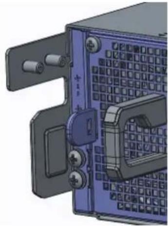
natural_image
3D CAD model of a mechanical assembly with mounting brackets and internal components (no visible text or symbols)Figure 6. Switch without ground lug
- Remove the ground lug from the shipping bag and crimp the ground wire to the lug.
The ground wire is not included.
NOTE: The grounding cable must comply with your local electrical codes in size and color. Wires are typically green or green with a yellow stripe.
- Attach the ground lug to the mounting bracket using two M5 nuts, included.
Torque to 30 in-lb.

natural_image
3D CAD model of a mechanical device with ports and mounting bracket (no visible text or symbols)Figure 7. Switch with ground lug
NOTE: For proper ventilation, position the chassis in an equipment rack or cabinet with a minimum of 5 inches (12.7 cm) of clearance around exhaust vents. The acceptable ambient temperature ranges are listed in the Environmental Parameters section.
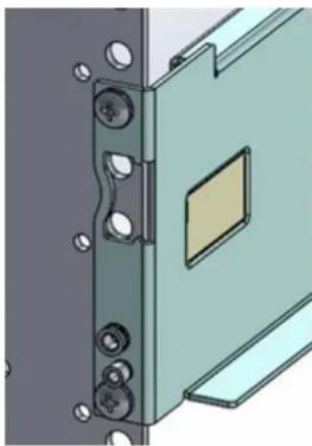
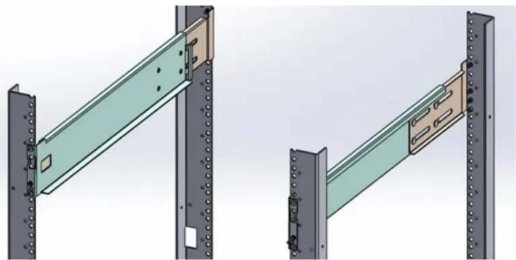
- Attach the rack rails to the rack using four screws on the front of the rack and eight screws on the back of the rack. Rack rail screws are not included.
natural_image
Technical illustration of a door panel with mounting holes and a central square component (no text or symbols)Figure 8. Attach rack rails to rack—front view
natural_image
Technical illustration of two structural beams with metal plates and mounting holes, shown from different angles (no text or symbols)Figure 9. Rack rails installed
- Insert the chassis into the rack from the front. Secure the chassis with captive screws and two additional rack screws on each side of the front of the rack.
Rack rail screws are not included.

natural_image
Close-up of a green electronic device with four circular ports and a connector (no visible text or symbols)Figure 10. Secure chassis in rack
- Attach the other end of the ground wire to the nearest appropriate facility grounding post.
For rack spans from 23.375 to 36 inches
The switch ships without the ground lug attached. To be NEBS-compliant, attach the ground lug using these steps.

natural_image
3D CAD model of a mechanical device with multiple ports and mounting brackets (no visible text or symbols)Figure 11. Switch without ground lug
- Remove the ground lug from the shipping bag and crimp the ground wire to the lug.
The ground wire is not included.

NOTE: The grounding cable must comply with your local electrical codes in size and color. Wires are typically green or green with a yellow stripe.
- Attach the ground lug to the mounting bracket using two M5 nuts, included.
Torque to ±30 in-lbs.

natural_image
3D rendering of a blue industrial control panel with ports and buttons (no visible text or symbols)Figure 12. Switch with ground lug
NOTE: For proper ventilation, position the chassis in an equipment rack or cabinet with a minimum of 5 inches (12.7 cm) of clearance around exhaust vents. The acceptable ambient temperature ranges are listed in the Environmental Parameters section.
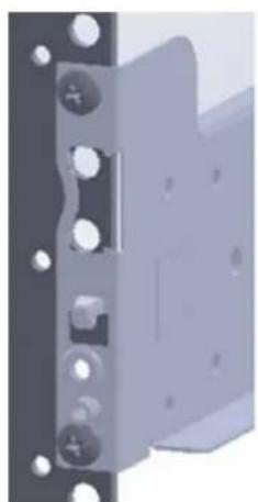
- Attach the rack rails to the rack using four screws on the front of the rack and eight screws on the back of the rack. Rack rail screws are not included.

natural_image
Technical illustration of two mechanical components with mounting holes and internal brackets (no text or symbols)Figure 13. Rack rails—rear view
natural_image
3D rendering of a mechanical component with bolt holes and mounting brackets (no text or symbols visible)Figure 14. Attach rack rails to rack—front view

natural_image
Two metal shelving units with vertical bolts, shown from different angles (no text or symbols visible)Figure 15. Rack rails installed
- Insert the chassis into the rack from the front. Secure the chassis with captive screws and two additional rack screws on each side of the front of the rack.
Rack rail screws are not included.

natural_image
Close-up of a green electronic device with multiple ports and connectors (no visible text or symbols)Figure 16. Secure chassis in rack
- Attach the other end of the ground wire to the nearest appropriate facility grounding post.
S6100-ON installation
To install the S6100-ON system, Dell recommends completing the installation procedures in the order presented.
Topics:
• Installation overview
• Unpack the S6100-ON System
- Four-post rack assembly
- Four-post rack mount
- Chassis ground
• I/O module installation
•SFP+ and QSFP optics installation
•SFP+ and QSFP optics removal
- Port connectivity
- System power-up
Installation overview
Always handle the S6100-ON and its components with care. Avoid dropping the system or its field replaceable units (FRUs). This topic describes the installation procedures as follows:
- Unpack the S6100-ON System.
- Install rack or cabinet hardware.
- Install the S6100-ON system.
- Install the SFP+ optics.
- Power up the system.
NOTE: Due to the weight of a fully populated S6100-ON chassis, remove each component before you install or remove the chassis.
NOTE: ESD damage can occur if components are mishandled. Always wear an ESD-preventive wrist or heel ground strap when handling the S6100-ON and its components. As with all electrical devices of this type, take all the necessary safety precautions to prevent injury when installing this system.
Unpack the S6100-ON System
Before unpacking the system, inspect the container and immediately report any evidence of damage. Verify that you have received your ordered items. If any item is missing or damaged, contact your Dell Networking representative or reseller for assistance.
CAUTION: Always wear an ESD-preventive wrist or heel ground strap when handling the switch and its components. Ground yourself by using an antistatic wrist strap or other device and connect it to the ESD grounding jack on the chassis. As with all electrical devices of this type, take all necessary safety precautions to prevent injury when installing this system.
CAUTION: Use an equipment lift or pallet jack to lift the shipping container with the chassis. Lifting the system by its shelves can damage the chassis.
When unpacking the S6100-ON switch, make sure that the following items are included:
●One S6100-ON switch
●One RJ-45 to DB-9 female cable
● Two sets of rail kits, no tools required
- Two PSUs
- Four fan units
●One AC or DC country and region-specific power cord
- One ground lug
- Dell Networking Getting Started Guide for the S6100-Open Networking (ON) System
●Safety and Regulatory Information
● Warranty and Support Information
Unpack the system by carefully removing the device from the container and placing it on a secure and clean surface.
Four-post rack assembly
Due to the chassis weight, the S6100-ON switch does not support a two-post rack installation; you must install the S6100-ON in a four-post rack.
To install in a four-post rack, follow the instructions in your rack frame kit. In a four-post rack, the maximum distance between the front and back vertical posts is 36 inches (91.44 cm); the minimum distance is 24 inches (60.96).

CAUTION: Use two people, an equipment lift, or pallet jack when lifting or moving the chassis. Install the chassis into the rack before inserting the chassis components. Lift the chassis only from the bottom. Lifting by the chassis shelves or power supply openings might damage the chassis.
Four-post rack mount
Rack Mounting Safety Considerations
NOTE: To prevent bodily injury when mounting or servicing this unit in a rack, take special precautions to ensure that the system remains stable. The following guidelines are provided to ensure your safety:
- If your chassis is the only unit in the rack, mount it at the bottom of the rack.
- When mounting this unit in a partially filled rack, load the rack from the bottom to the top. Be sure that the heaviest component is at the bottom of the rack.
- If the rack comes with stabilizing devices, install the stabilizers before mounting or servicing the unit in the rack.
- If the chassis ships with blanks, remove the blanks from each slot before lifting the chassis.
NOTE: These instructions are a condensed reference. Read the safety instructions in your Safety, Environmental, and Regulatory information booklet before you begin.
- Rack loading—Overloading or uneven loading of racks may result in shelf or rack failure, which may damage equipment and cause possible personal injury. Stabilize racks in a permanent location before loading begins. Mount the components starting at the bottom of the rack, then work to the top. Do not exceed your rack load rating.
- Power considerations—Connect only to the power source specified on the unit. When you install multiple electrical components in a rack, ensure that the total component power ratings do not exceed the circuit capabilities. Overloaded power sources and extension cords present fire and shock hazards.
- Elevated ambient temperature—If you install the switch in a closed rack assembly, the operating temperature of the rack environment may be greater than the room ambient temperature. Use care not to exceed the 40^ C maximum ambient temperature of the switch.
- Reduced air flow—Install the equipment in the rack so that the amount of airflow required for safe operation of the equipment is not compromised.
- Reverse air flow—To ensure cool air intake and to avoid hot air blow out from I/O panel, ensure that you have the necessary clearance.
- Reliable earthing—Maintain reliable earthing of rack-mounted equipment. Pay particular attention to the supply connections other than the direct connections to the branch circuit; for example, use of power strips.
- Do not mount the equipment with the utility panel facing in the downward position.

NOTE: The illustrations in this document are not intended to represent a specific switch.
- Align the system with rails and slide the system into rack.
- Tighten the screws on each side of the systems's front panel, item 1.
To remove the system from the rack, loosen the screws and slide the system out of the rack.

Figure 17. S6100-ON system installation
- Extra screws to restrict front-back movement of the switch
- Main screw
Chassis ground
After you mount the chassis, secure the chassis ground as follows:
To properly ground the chassis, Dell recommends using the two-hole lug shipped in a separate plastic bag with your chassis. The two-hole lug must be a UL recognized, crimp-type lug. To connect the ground cable to the framework or cabinet and to mount the unit, use thread-forming unit mounting screws that remove paint or nonconductive coatings.

CAUTION: Grounding conductors must be made of copper. Do not use aluminum conductors.
NOTE: The rack installation ears are not suitable for grounding.
NOTE: Coat the two-hole lug with an anti-oxidant compound before crimping. Also, bring any unplated mating surfaces to a shiny finish and coat with an anti-oxidant before mating. Plated mating surfaces must be clean and free from contamination.
NOTE: Never use the same bolts to secure multiple grounding cables.
- Locate the chassis ground lug nuts and holes on the chassis back.

Figure 18. Chassis ground connector
a. Ground cable
b. Two-hole chassis ground connector
- Install the grounding cables to the ground nuts.
The grounding cable must comply with your local electrical codes in size and color. Wires are typically green or green with a yellow stripe.

NOTE: For proper ventilation, position the chassis in an equipment rack or cabinet with a minimum of 5 inches (12.7 cm) of clearance around exhaust vents. The acceptable ambient temperature ranges are listed in the Environmental Parameters section.
- Tighten the M5 screws, torque between 18 and 24 in-lbs.
- Connect the opposite end of the grounding cable to the nearest appropriate facility grounding post.

Figure 19. Cable connector
a. High-strand-count conductor
b. Two-holes for cable—.27 ±.02 DIA
I/O module installation
NOTE: Install a blank panel in any unused switch I/O slot.
NOTE: The S6100-ON has capacitors on the front-left corner of the PC board. To avoid damaging these capacitors, align the I/O module with the yellow arrows located inside the chassis and then gently slide the I/O module in place.
-
Remove the I/O module from the electro-static bag.
-
Open the left ejector lever, item 1, by pressing in the orange tab, item 2, and rotating it to the right.
The level snaps into the open position.
- Slide the I/O module into the switch I/O slot.
The slot is keyed so that the I/O module fully inserts in only one way. When you install the I/O module correctly, it snaps into place and is flush with the back of the switch.
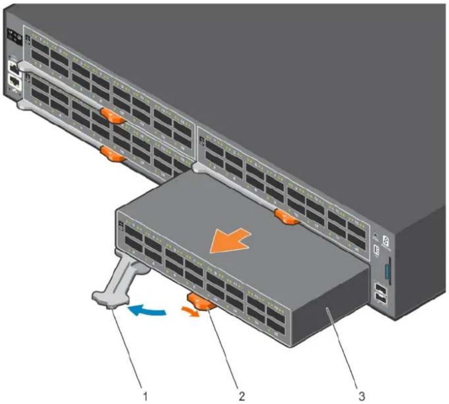
Figure 20. I/O module installation
a. Ejector lever
b. Orange release tab
c. I/O module
Important points
The S6100-ON is designed to support two hot-swappable power supplies with integrated fans that provide cooling for the chassis.
●The S6100-ON ships with two power supplies.
- The PSU slides into the slot smoothly. Do not force the PSU into a slot as this action may damage the PSU or the S6100-ON chassis.
- The S6100–ON supports AC and DC power supplies with two air-flow directions—I/O to PSU and PSU to I/O. The S6100–ON does not support mixing PSU types. The fan airflow direction for the PSUs must be the same.
- Module power is software controlled. You do not see module LEDs when the system powers up.
CAUTION: DO NOT mix airflow directions. Both power supplies must use the same airflow direction—I/O to PSU or PSU to I/O.
NOTE: Although the switch can run on one PSU, Dell highly recommends using two PSUs for full redundancy and extra cooling. To avoid overheating when the switch is running with a single PSU, install the second PSU.
NOTE: ESD damage can occur if components are mishandled. Always wear an ESD-preventive wrist or heel ground strap when handling the S6100-ON and its components.
NOTE: To prevent electrical shock, ensure that the S6100-ON is grounded properly. If you ground your equipment incorrectly, excessive emissions may result. To ensure that the power cables meet your local electrical requirements, use a qualified electrician.
NOTE: The Utility panel consists of two slots, PSU1 and PSU2. Insert PSUs in both slots.
NOTE: If you remove and re-insert a module in the same slot, the system detects the module. However, if you remove a module from a slot and insert a different module into that same slot, the system does not detect the new module.
SFP+ and QSFP optics installation
The S6100-ON has SFP+, QSFP+, and QSFP28 optical ports.
For a list of supported optics, contact your Dell representative.
CAUTION: ESD damage can occur if components are mishandled. Always wear an ESD-preventive wrist or heel ground strap when handling the S6100-ON and its components.
WARNING: When working with optical fibers, follow all warning labels and always wear eye protection. Never look directly into the end of a terminated or unterminated fiber or connector as this action can cause eye damage.
- Position the optic so it is in the correct position.
The optic has a key that prevents it from being inserted incorrectly.
- Insert the optic into the port until it gently snaps into place.
NOTE: When you cable the ports, be sure not to interfere with the airflow from the small vent holes above and below the ports.
SFP+ and QSFP optics removal
Remove an SFP+, QSFP+, or QSFP28 optic by pulling the tab on the optic and sliding the optic from the port.
CAUTION: When removing optics with direct attach cables (DACs) from the port, pull the release tab firmly and steadily. If you have difficulties pulling out the cable, gently push the optic into the port with one hand and at the same time pull the release tab slightly upwards, towards the cable or module center, with the other hand. Do not jerk or tug repeatedly on the tab.
Port connectivity
Dell recommends you distribute port groups across all four port pipes.
The S6100-ON switch has four port pipes, also known as packet processing pipelines. Because S6100-ON is a modular switch, connectivity between the front panel ports and the port pipes depends on the module type of the four slots. For the best buffer resource usage, distribute the functional port groups, such as downlinks, uplinks, interchassis links, LAGs, and ECMP across all four port pipes—0, 1, 2, and 3. If that is not possible, distribute the port groups across port pipes 0 and 2 or port pipes 1 and 3.
For example, with 8 x 100G modules, create a two-port LAG using port 1/7 from port pipe 0 and port 1/4 from port pipe 2. With 16 x 40G modules, create a four-port LAG using port 1/12 from port pipe 1, 1/14 from port pipe 0, 2/11 from port pipe 2, and 2/13 from port pipe 3. With 4 x CXP + 4 x QSFP28 modules, create a two-port LAG using port 1/6 from port pipe 1 and port 2/7 from port pipe 2.
The following tables list the port to port pipe connectivity for the 8 x 100G modules, 16 x 40G modules, and 4 x CXP + 4 x QSFP28 modules:
Table 6. Port and port pipe distribution—8 x 100G modules
| Slot/Port Port pipe | |
| 1/7, 1/8, 2/1, 2/2, 3/1, 3/2, 4/3, 4/4 0—red | |
| 1/5, 1/6, 2/3, 2/4, 3/7, 3/8, 4/5, 4/6 1—orange | |
| 1/3, 1/4, 2/5, 2/6, 3/5, 3/6, 4/7, 4/8 2—green | |
| 1/1, 1/2, 2/7, 2/8, 3/3, 3/4, 4/1, 4/2 3—blue |

Figure 21. 8 x 100G module port pipes
Table 7. Port and port pipe distribution—16 x 40G modules
| Slot/Port Port pipe | |
| 1/13, 1/14, 1/15, 1/16, 2/1, 2/2. 2/3. 2/4, 3/1, 3/2, 3/3, 3/4, 4/5, 4/6, 4/7, 4/8 | 0—red |
| 1/9, 1/10, 1/11, 1/12, 2/5, 2/6, 2/7, 2/8, 3/13, 3/14, 3/15, 3/16, 4/9, 4/10, 4/11, 4/12 | 1—orange |
| 1/5, 1/6, 1/7, 1/8, 2/9, 2/10, 2/11, 2/12, 3/9, 3/10, 3/11, 3/12, 4/13, 4/14, 4/15, 4/16 | 2—green |
| 1/1, 1/2, 1/3, 1/4, 2/13, 2/14, 2/15, 2/16, 3/5, 3/6, 3/7, 3/8, 4/1, 4/2, 4/3, 4/4 | 3—blue |

Figure 22. 16 x 40G module port pipes
Table 8. Port and port pipe distribution—4 x CXP + 4 x QSFP28 modules
| Slot/Port Port pipe | ||
| 1/7, 1/8, 2/1, 2/2, 3/1, 3/2, 4/3, 4/4 0—red | ||
| 1/5, 1/6, 2/3, 2/4, 3/7, 3/8, 4/5, 4/6 1—orange | ||
| 1/3, 1/4, 2/5, 2/6, 3/5, 3/6, 4/7, 4/8 2—green | ||
| 1/1, 1/2, 2/7, 2/8, 3/3, 3/4, 4/1, 4/2 3—blue |

Figure 23. 4 x CXP + 4 x QSFP28 port pipes
System power-up
Supply power to the S6100-ON after it is mounted in a rack or cabinet.
Dell recommends reinspecting your system before powering up. Verify the following:
- The equipment is properly secured to the rack and properly grounded—recommended.
●The equipment rack is properly mounted and grounded—recommended. - The ambient temperature around the unit, which may be higher than the room temperature, is within the limits specified for the S6100–ON, see Specifications.
●There is sufficient airflow around the unit. - The input circuits are correctly sized for the loads and that you use sufficient overcurrent protection devices.
- All protective covers are in place.
- All I/O modules are installed.

CAUTION: Do not power up the switch if you did not install a fan module.
NOTE: A US AC or DC power cable is included for powering up an AC or DC power supply. You must order all other power cables separately.
NOTE: ESD damage can occur if components are mishandled. Always wear an ESD-preventive wrist or heel ground strap when handling the S6100-ON system and its components.
Power up sequence
When the system powers up, the fans immediately come on at high speed. The fan speed slows as the system continues to boot up.
- Verify that the power source complies with the system input power requirements.
- Connect a power plug to each power connector. Make sure that the power cord is secure.
- Connect the power cable to each power supply and to a power source. The PSU LED for power blinks green to indicate that each PSU is receiving power from an outlet.
When you turn on the power supplies and supply power to the chassis, the system performs a series of power-on self-tests (POSTs). No user interaction is required during the POST.

NOTE: Module power is software controlled. You do not see module LEDs when the system powers up in ONIE.
Power supplies
The S6100-ON supports AC or DC power supplies with two air-flow directions, normal and reverse. Normal airflow is from the I/O to the PSU and reverse airflow is from the PSU to the I/O.
Two PSUs are required for full redundancy, but the system can operate with a single PSU. To protect against high-voltage shock, install a power supply blank in all unused power supply slots.
The PSU is field replaceable. When running with full redundancy—two power supplies installed and running, you can remove and replace one PSU without disrupting traffic.

CAUTION: To prevent electrical shock, ensure that the S6100-ON is grounded properly. If you do not ground your equipment correctly, excessive emissions may result. Use a qualified electrician to ensure that the power cables meet your local electrical requirements.

NOTE: Connect the power supply to the appropriate branch circuit protection as defined by your local electrical codes. Verify that the remote power source complies with the system input power specifications.

NOTE: ESD damage can occur if components are mishandled. Always wear an ESD-preventive wrist or heel ground strap when handling the S6100-ON and its components.
Topics:
- Components
• AC or DC power supply installation
• AC or DC power supply replacement
Components
The following power supply options are available for the S6100-ON:
●AC or DC power supply with integrated fan
●AC or DC power supply with integrated reverse flow fan
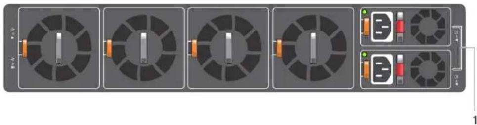
Both PSUs are on the right side of the switch. Power supply 1, PSU1, is on the top of the chassis; power supply 2, PSU2, is on the bottom of the chassis.
flowchart
graph LR
    A["Component 1"] --> B["Component 2"]
    B --> C["Component 3"]
    C --> D["Component 4"]
    D --> E["Component 5"]
    E --> F["Terminal Block"]
    style A fill:#f9f,stroke:#333
    style B fill:#f9f,stroke:#333
    style C fill:#f9f,stroke:#333
    style D fill:#f9f,stroke:#333
    style E fill:#f9f,stroke:#333
    style F fill:#f9f,stroke:#333
Figure 24. S6100-ON PSUs
1. PSU 1 and 2
The PSUs have an integrated fan, which you cannot replace individually; if the fan integrated in a PSU fails, you must replace the entire PSU. You can replace the fan trays individually. For fan tray replacement procedures, see Fans.

WARNING: Prevent exposure and contact with hazardous voltages. Do not attempt to operate this system with the safety cover removed.
CAUTION: Remove the power cable from the PSU before removing the PSU. Also, do not connect the power cable before you insert the PSU in the chassis.
NOTE: To comply with the GR-1089 Lightning Criteria for Equipment Interfacing with AC Power Ports, use an external surge protection device (SPD) at the AC input of the router.
AC or DC power supply installation
NOTE: The PSU slides into the slot smoothly. Do not force a PSU into a slot as this action may damage the PSU or the S6100-ON chassis.
NOTE: Ensure that you correctly install the PSU. When you install the PSU correctly, the power connector is on the right side of the PSU.
- Remove the PSU slot cover from the S6100-ON using a small #1 Phillips screwdriver.
- Remove the PSU from the electro-static bag.
- Use the grab handle and the orange tab to insert the PSU into the switch PSU slot.
Insert the PSU exposed PCB edge connector first. The PSU slot is keyed so that the PSU can only be fully inserted in one orientation.

Figure 25. Power supply installation
a. Power supply unit
b. Release tab
When you install the PSU correctly, it snaps into place and is flushed with the back of the switch.
- Plug in the appropriate AC three prongs power cord from the switch PSU to the external power source.
- Repeat steps 1 through 4 above using the second PSU slot on the S6100-ON system.
NOTE: The S6100-ON powers up when the cables are connected between the power supply and the power source.
DC power supply connection
Each DC powered system comes with a set containing a prewired, 3-inch 8 AWG, power supply connector and a four-screw wiring block. One set is provided for each DC PSU.

Figure 26. DC power connector and wiring block
- DC wire RTN 2. DC power connector
- Two Captive screws 4. Release tab
- PSU status LED 6. DC power socket
- DC wire -48V
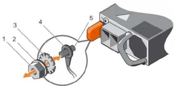
Figure 27. DC power connector ground
- Ground nut 2. Washer
- Lock washer 4. Ground cable
-
Device grounding rod
-
Strip 1/2 inches of insulation from each of the power connector's red and black wires, as shown.
-
Insert each of the power connector's bare wire lengths into the wiring block. Insert red into one hole and black into the other hole, as shown.
-
Use a flat-blade screwdriver to tighten the screws that secures the bare wires into the wiring block.
- Secure the site's DC power source wires to the other side of the wiring block, see steps 1 and 3.
NOTE: Do not cross the wires—in the wiring block, red aligns with red and black aligns with black.
- Insert the DC power connector into the power socket of the DC PSU. Ensure that the connector pins firmly seat and you hear the click of the power connector's left and right levered clamps lock into place.
NOTE: Never try to force the power connector into or out of the DC PSU power socket.
NOTE: To remove the power connector from a DC PSU, squeeze the levers on both sides of the connector. Doing so disengages the power connector's clamps. While continuing to squeeze, pull the power connector from the DC PSU socket.
AC or DC power supply replacement
CAUTION: Disconnect the power cord before removing the power supplies. Also, disconnect all power cords before servicing.
NOTE: The PSU slides into the slot smoothly. Do not force a PSU into a slot as this action may damage the PSU or the S6100-ON chassis.
NOTE: If a PSU fails, you must replace the entire unit. There are no field serviceable components in the PSU. To request a hardware replacement, see Dell Support.
- Disconnect the power cable from the PSU.
- Use the grab handle and the orange tab to slide the PSU out of the power supply bay.
- Use the grab handle and the orange tab on the replacement PSU to slide it into the power supply bay.
- Attach the power cord to the replacement PSU.
NOTE: The system powers up when the cables are connected between the power supply and the power source.
The S6100-ON comes from the factory with two PSUs and four fan module installed in the chassis. The fan module and power supply, which have integrated fans, are hot-swappable.
In addition to the power supply modules, you can order and install fan modules separately.
The S6100-ON supports two airflow direction options. DO NOT mix airflow types in a chassis; you can use only a single airflow direction in a chassis. If the airflow directions are mismatched, the S6100-ON issues an alarm. You must correct the mismatched airflow direction.
The fans and PSUs are color coded for air flow direction. Red is normal air flow and blue is reverse air flow.
●Normal—airflow is from the I/O panel to the PSU—red.
●Reversed—airflow is from the PSU to the I/O panel—blue.
All fans and PSUs in a configuration must be in the same airflow direction.
Environmental factors can decrease the amount of time required between fan replacements. Check the environmental factors regularly. An increase in temperature and particulate matter in the air might affect performance; for example, new equipment installation.

CAUTION: Check the fans at six-month intervals and replace them as necessary. Regularly monitor the speeds of the fans to accurately determine replacement intervals.
Topics:
- Components
•Fan module installation
•Fan module replacement
•Fan air filter replacement
•After system installation
Components
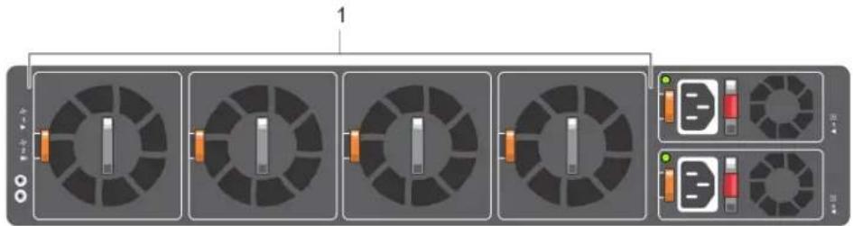
The following are the S6100-ON fan components:
●S6100-ON Fan module
●S6100-ON Fan module—reverse flow
flowchart
graph LR
    A["Component 1"] --> B["Component 2"]
    B --> C["Component 3"]
    C --> D["Component 4"]
    D --> E["Component 5"]
    E --> F["Output Port 1"]
    style A fill:#f9f,stroke:#333
    style B fill:#ccf,stroke:#333
    style C fill:#cfc,stroke:#333
    style D fill:#fcc,stroke:#333
    style E fill:#cff,stroke:#333
    style F fill:#ffc,stroke:#333
The fan module in the S6100-ON is field replaceable.
Module slot 1 is on the left side of the chassis and module slot 4 is on the right side of the chassis.

CAUTION: DO NOT mix airflow directions. All fans must use the same airflow direction—reverse or normal. If you mix the airflow direction, the switch detects the discrepancy, issues an alarm, and may auto-shutdown to avoid heat damage to components. You must correct the mixed airflow direction.
-
Take the fan module out of the shipping box.
-
Use the grab handle and the orange tab to slide the module into the bay.

natural_image
3D diagram of a server rack with multiple fans and power connectors, showing internal components and directional arrows (no text or symbols)Figure 29. Fan module installation
a. Release tab
b. Fan module
Fan module replacement

NOTE: Never leave the fan partially inserted. The fan stalls if it is left partially inserted.
- Use the grab handle and the orange tab to slide the fan module out of the bay.
- Use the grab handle and the orange tab to slide the replacement module into the bay.
Fan air filter replacement
Environmental factors can decrease the amount of time required between air filter replacements. Check the environmental factors regularly. An increase in temperature and/or particulate matter in the air might affect performance.

CAUTION: Check the fan air filters at six-month intervals and replace them as necessary. To accurately determine air filter replacement intervals, regularly monitor the speeds of the cooling fans. An increase in overall fan speed may indicate a clogged filter.
You must replace the fan air filters with new filters; you cannot clean and reuse the old fan air filters. Replacement filter media must meet the requirements found in GR-63-CORE.
●Minimum dust arrestance of 65%, per ASHRAE Standard 52.1-1992. OR
●Minimum Efficiency Rating Value (MERV) of 2, per ANSI/ASHRAE Standard 52.2-2007.

CAUTION: For NEBS compliance, use NEBS-approved filters.
Use fan air filters with reverse air flow systems—blue banded PSUs and fans. You can replace the air filters individually on each fan within the system without powering down a PSU module or disrupting traffic.
The fan air filter media slides into the frame from the top. No tools are required.
- Determine which filters to replace.
- Unlatch and remove the first module that needs the filter replaced.
- Slide the existing filter upwards to remove it from the module.
- Replace the filter with a new filter of the same size.
- Repeat for the remaining modules that need the filter replaced.
After system installation
After you have securely installed and powered on the S6100-ON, to configure your system, see your third-party ONIE-compatible OS or Dell OS documentation.
Management ports
Besides the 10/25/40/50/100 GbE RJ-45 ports, the S6100–ON system provides several ports for management and storage.
Topics:
•RS-232 console port access
- Micro USB-B console port access
- USB storage
•Before you install an OS
•ONIE service discovery
RS-232 console port access
The RS-232 console port is on the I/O-side of the S6100-ON chassis, as shown.

natural_image
Front view of a network switch interface with multiple Ethernet ports and indicator lights (no readable text or symbols)Figure 30. S6100-ON RS-232 console ports
- Top: RS-45 console port; bottom: RJ-45 management port

CAUTION: Ensure that any equipment attached to the serial port can support the required 115200 baud rate.
NOTE: When connecting the RJ45 console to the patch panel or terminal server using Cat5e or Cat6 Ethernet cables, the maximum cable length is 100m. However, if the Ethernet cable is disconnected from the patch panel or terminal server but connected to the RJ45 console, the maximum cable length is 6m. If the cable is longer than 6m when disconnected from the panel or server, your switch may not boot.
NOTE: Be sure that your PC has a 9-pin serial port and that you have a terminal emulation program already installed and running on the PC.
NOTE: If your PC's serial port cannot accept a female DB-9 connector, acquire a DB-9 male-to-male adaptor.
- Install the provided RJ-45 connector side of the provided cable into the S6100-ON console port.
- Install the DB-9 female side of the provided copper cable into your PC's serial port or into other data terminal equipment (DTE) server hardware.
- Keep the default terminal settings on the console as follows:
●115200 baud rate
- No parity
- 8 data bits
- 1 stop bit
- No flow control
Accessing the RJ-45 Console Port with a DB-9 Adapter
You can connect to the console using an RJ-45 to RJ-45 rollover cable and an RJ-45 to DB-9 female DTE adapter to a terminal server (for example, a PC).
The pin assignments between the console and a DTE terminal server are as follows:
Table 9. Pin Assignments Between the Console and a DTE Terminal Server
| S6100-ON Console Port | RJ-45 to RJ-45 Rollover Cable | RJ-45 to RJ-45 Rollover Cable | RJ-45 to DB-9 Adapter | Terminal Server Device |
| Signal RJ-45 Pinout RJ-45 Pinout DB-9 Pin Signal | ||||
| NC 18 8 CTS | ||||
| NC 2 7 6 DSR | ||||
| TxD 3 6 2 RxD | ||||
| GND 4 5 5 GND | ||||
| GND 5 4 5 GND | ||||
| RxD 6 3 3 TxD | ||||
| NC 7 2 4 DTR | ||||
| NC 8 1 7 RTS | ||||
Micro USB-B console port access
The Micro USB type B console port is on the I/O side of the switch.

NOTE: The S6100-ON switch uses the Silicon Labs CP2102 USB-B chip. To find the correct USB-B universal asynchronous receiver-transmitter (UART) driver, see https://www.silabs.com/products/development-tools/software/usb-to-uart-bridge-vcp-drivers.
When you connect the micro USB-B port, it becomes the primary connection and, while connected, all messages are sent to the micro USB-B port.
- Power on the PC.
- Connect the USB-A end of cable into an available USB port on the PC.
- Connect the micro USB-B end of cable into the micro USB-B console port on the S6100-ON.
- Power on the S6100-ON.
- Install the necessary USB device drivers.
- Open your terminal software emulation program to access the S6100-ON.
- Confirm that the terminal settings on your terminal software emulation program are as follows:
●115200 baud rate
- No parity
- 8 data bits
- 1 stop bit
- No flow control
USB storage
The USB storage supports the FAT file system. The USB storage does not automatically mount. To use USB storage, first mount the device.
- Create a mount directory for the USB.
ONIE:/ # mkdir /mnt/usb
- View the fixed disks using the fdisk command.
ONIE:/mnt # fdisk -1
For internal storage:
Disk /dev/sda: 15.8 GB, 15829303296 bytes
255 heads, 63 sectors/track, 1924 cylinders
Units = cylinders of 16065 * 512 = 8225280 bytes
Device Boot Start End Blocks Id System
/dev/sda1 1 1925 15458303+ ee EFI GPT
For USB storage:
Disk /dev/sdb: 30.9 GB, 30942946304 bytes
64 heads, 32 sectors/track, 29509 cylinders
Units = cylinders of 2048 * 512 = 1048576 bytes
Device Boot Start End Blocks Id System
- Mount the device /dev/sdb to the /mnt/usb directory.
ONIE: / # mount -t vfat /dev/sdb /mnt/usb

NOTE: The following message displays if the /mnt/usb directory is missing: mount: mounting /dev/sdb on /mnt/usb failed: No such file or directory.

NOTE: The following message displays if the USB device is not seen: mount: mounting /dev/sdb on /mnt/usb failed: No such device or address.
- Add a device to the file systems table, fstab, and mount the file systems.
ONIE:/ # vi /etc/fstab
<h1 id="fstab-entry-for-the-onie-boot-partition-mounted-on-boot">FSTAB entry for the ONIE-BOOT partition mounted on /boot</h1>
LABEL=ONIE-BOOT /mnt/onie-boot ext4 defaults,rw,errors=remount-ro 0 1
/dev/sdb /mnt/usb vfat defaults 0 1
ONIE:/ # mount -a
Before you install an OS
After powering on the S6100-ON system, it goes through a power-on self-test (POST).
POST runs every time the switch is initialized and checks the hardware components to determine if the switch is fully operational before booting. After POST, the system uses the Grub bootloader.
To select an entry, use the up and down arrow keys. Press Enter to select an OS or enter e to edit the commands before booting. Enter c for a command line. The selected entry runs automatically in the operating system.

NOTE: These output examples are for reference only; your output may be different.
Grub bootloader example
GNU GRUB version 2.02~beta2+e4a1fe391
*ONIE: Install OS
ONIE: Rescue
ONIE: Uninstall OS
ONIE: Update ONIE
ONIE: Embed ONIE
ONIE: Diag ONIE
Your system comes with ONIE installed.
ONIE example
ONIE: Install OS
For downloading and installing an OS from a URL
Starts ONIE with ONIE Discovery Service
(factory default boot)
ONIE: Rescue
Starts ONIE without ONIE Discovery Service
Useful for running Diagnostics manually
ONIE: Uninstall OS
Restore to factory defaults erases any installed OS
ONIE: Update ONIE
For downloading and updating ONIE from a URL
ONIE: Embed ONIE
For downloading and updating ONIE from a URL and erases any installed OS
ONIE: Diag ONIE
Run Diagnostic package for S6100-ON
During the initial setup, the system boots to ONIE Install. ONIE Install boots with ONIE Discovery to the console—ONIE:.
ONIE service discovery
ONIE attempts to locate the installer through several discovery methods, as shown. To download and run an installer, the ONIE Service Discovery feature uses the first successful method found.
- Search locally attached storage devices for one of the ONIE default installer filenames—for example, the filename is: onie self update from the USB.
- Query to the IPv4 and IPv6 link-local neighbors using HTTP for an installer.
- Discover TFTP-based image from the DHCP server.
If none of the ONIE Service Discovery methods are successful, you can disable this using the onie-discovery-stop command.
You can install an operating system manually from HTTP, FTP, or TFTP using the onie-nos-install
The ONIE Install environment uses DHCP to assign an IP address to the management interface, eth0. If that fails, it uses the default IP address 192.168.3.10/255.255.255.0.

NOTE: These output examples are for reference only; your output may be different.
To display the IP address, use the ifconfig eth0 command, as shown.
ONIE:/ # ifconfig eth0
eth0 Link encap:Ethernet HWaddr 90:B1:1C:F4:9C:76
inet addr:10.11.53.33 Bcast:10.255.255.255 Mask:255.0.0.0
inet6 addr: fe80::92b1:1cff:fef4:9c76/64 Scope:Link
UP BROADCAST RUNNING MULTICAST MTU:1500 Metric:1
RX packets:18 errors:0 dropped:0 overruns:0 frame:0
TX packets:24 errors:0 dropped:0 overruns:0 carrier:0 collisions:0 txqueuelen:1000
RX bytes:1152 (1.1 KiB) TX bytes:6864 (6.7 KiB)
Interrupt:21 Memory:ff300000-ff320000
To assign an IP address to the management interface, eth0, and verify network connectivity, use the ifconfig eth0
ONIE:/ # ifconfig eth0 10.11.53.33/16
Verify the network connection with ping.
ONIE:/ # ping 10.11.8.12
PING 10.11.8.12 (10.11.8.12): 56 data bytes
64 bytes from 10.11.8.12: seq=0 ttl=62 time=1.357 ms
64 bytes from 10.11.8.12: seq=1 ttl=62 time=0.577 ms
^C
Dell support
The Dell Support site provides a range of documents and tools to help you effectively use the Dell equipment and the impact of network outages. You can obtain technical information regarding Dell products, access software upgrades and patches, download available management software, and manage your open cases. The Dell support site provides integrated, secure access to these services.
To access the Dell Support site, go to www.dell.com/support/. To display information in your language, scroll down to the bottom of the web page and select your country from the drop-down menu.
- To obtain product-specific information, enter the 7-character service tag, known as a luggage tag, or 11-digit express service code of your switch and click Submit.
To view the chassis service tag or express service code, pull out the tag or enter the show chassis command from the CLI. The service tag is one the I/O-side, bottom-left, of the system.
- To receive more kinds of technical support, click Contact Us. On the Contact Information web page, click Technical Support.
To download system documentation, go to www.dell.com/manuals/.
To search for drivers and downloads, go to www.dell.com/drivers/.
To participate in the Dell community blogs and forums, go to www.dell.com/community.
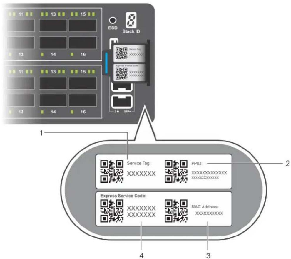
Figure 31. S6100-ON luggage tag
- Service tag 2. PPID
- MAC address 4. Express service code
Specifications
This topic lists the S6100–ON specifications.
CAUTION: Operate the product at an ambient temperature not higher than 113^ F ( 45^ C).
CAUTION: Lithium Battery Caution: There is a danger of explosion if the battery is incorrectly replaced. Replace only with same or equivalent type of battery. Dispose of the batteries according to the manufacturer's instructions.
NOTE: For RoHS information, see Restricted Material Compliance.
Topics:
• Chassis physical design
- IEEE standards
•Agency compliance
• USA Federal Communications Commission (FCC) statement
• European Union EMC Directive Conformance statement
•Japan: VCCI Compliance for Class A Equipment
• Korean Certification of Compliance
•Safety Standards and Compliance Agency Certifications
•Electromagnetic Compatibility (EMC)
•Product recycling and disposal
Chassis physical design
Table 10. Chassis physical design
| Parameter Specifications | |
| Height 3.50 inches (88.9 mm) | |
| Width 17.1 inches (434.3 mm) | |
| Depth 18 inches (457.2 mm) | |
| Chassis Weight with Factory-Installed Components 44 lbs (20 kg)—with two PSUs and four I/O modules | |
| Rack Clearance Required | Front: 5 inches (12.7 cm)Rear: 5 inches (12.7 cm) |
Table 11. Environmental Parameters
| Parameter Specifications | |
| Operating Temperature 32° to 113°F (0° to 45°C) | |
| Operating Humidity 5 to 95 percent (RH), non-condensing | |
| Storage Temperature -40° to 158°F (-40° to 70°C) | |
| Storage Humidity 5 to 95 percent, non-condensing | |
| Thermal Output | Typical: 1170.4 BTU/hr (343 W)Maximum: 3057.3 BTU/hr (896 W) |
| Maximum operational altitude 10,000 feet (3,048 meters) | |
| Maximum non-operational altitude No performance degradation to 35,000 feet (10,668 meters) | |
| Shock SV0115 — ODM |
Table 12. AC power requirements
| Parameter Specifications | |
| Power Supply 100–240 VAC 50/60 Hz | |
| Maximum Current Draw Per System 12A–6.5A @ 100–240 VAC | |
| PSU Maximum Power Capability 1100 Watts | |
| Typical and Maximum Power Consumption | 343 Watts typical896 Watts maximum |
| Reliability MTBF 1,154,397 hours |
Table 13. DC power requirements
| Parameter Specifications | |
| PSU Maximum Power Capability 1100 Watts | |
| PSU Maximum current required 32A | |
| Minimum and maximum input voltage range -40.5 V / -48 V/ -60 V | |
| Input power at full load | -40.5 V/970 W -48 V/930 W -60 V/950 W, without fan-40.5 V/980 W -48 V/940 W -60V/ 960 W, with fan |
| Input current at full load | -40.5V/23.8A -48V/19.0A -60V/ 15.6A, without fan-40.5V/24.0A -48V/19.2A -60V/ 16.0A, with fan |
| Start up VDC 39.0+/-1.5 V | |
| Start off VDC 37.5+/-1.5 V |
IEEE standards
The S6100-ON complies with the following IEEE standards:
●802.3ab Gigabit Ethernet (1000BASE-T)
●802.3ae 10 Gigabit Ethernet (10GBASE-X)
●802.3ba 40 Gigabit Ethernet (40GBase-SR4, 40GBase-CR4) on optical ports
●802.3ba 100 Gigabit Ethernet
●802.3bj 100 Gigabit Ethernet
●802.3bm 100 Gigabit Ethernet
Agency compliance
The S6100-ON is designed to comply with the following safety and agency requirements.
USA Federal Communications Commission (FCC) statement
This equipment has been tested and found to comply with the limits for a Class A digital device, pursuant to Part 15 of the FCC rules. These limits are designated to provide reasonable protection against harmful interference when the equipment is operated in a commercial environment. This equipment generates, uses, and can radiate radio frequency energy. If it is not installed and used in accordance to the instructions, it may cause harmful interference to radio communications. Operation of this equipment in a residential area is likely to cause harmful interference, in which case users will be required to take whatever measures necessary to correct the interference at their own expense.
Properly shielded and grounded cables and connectors must be used in order to meet FCC emission limits. Dell is not responsible for any radio or television interference caused by using other than recommended cables and connectors or by unauthorized changes or modifications in the equipment. Unauthorized changes or modification could void the user's authority to operate the equipment.
This device complies with Part 15 of the FCC Rules. Operation is subject to the following two conditions: (1) this device may not cause harmful interference, and (2) this device must accept any interference received, including interference that may cause undesired operation.
Industry Canada Class A emission compliance statement
This Class A digital apparatus complies with Canadian ICES-003.
Figure 32. Canadian Department of Communication statement
European Union EMC Directive Conformance statement
This product is in conformity with the protection requirements of EU Council Directive 2004/108/EC on the approximation of the laws of the Member States relating to electromagnetic compatibility. Dell Networking can not accept responsibility for any failure to satisfy the protection requirements resulting from a non-recommended modification of this product, including the fitting of non-Dell Networking option cards.
This product has been tested and found to comply with the limits for Class A Information Technology Equipment according to CISPR 22/European Standard EN 55022. The limits for Class A equipment were derived for commercial and industrial environments to provide reasonable protection against interference with licensed communication equipment.

NOTE: This is a Class A product. In a domestic environment, this device may cause radio interference, in which case, you may be required to take adequate measures.
European Community Contact
Dell Networking, EMEA - Central
Dahlienweg 19
66265 Heusweiler
Germany
http://www.force10networks.com/german/
Tel: +49 172 6802630
Email: EMEA Central Sales
Japan: VCCI Compliance for Class A Equipment
Figure 33. Japan: VCCI Compliance for Class A Equipment
This is Class A product based on the standard of the Voluntary Control Council For Interference by Information Technology Equipment (VCCI). If this equipment is used in a domestic environment, radio disturbance may arise. When such trouble occurs, the user may be required to take corrective actions.

NOTE: Use the AC power cords with Dell Networking equipment only. Do not use Dell Force10 AC power cords with any unauthorized hardware.
Figure 34. Japan: Warning Label
Korean Certification of Compliance
Figure 35. Korean Certification of Compliance
 [equipment type] [equipment type] | |
| 품명(Product Name) | Ethernet Switch |
| 모델명(Model) | [model number] |
| 신청인(Applicant) | Force10 Networks, Inc. |
| 제조자(Manufacturer) | Delta Networks, (Dongguan) Ltd. |
| 제조년월(Manufacturing Date) | [date] |
| 제조국(Country of Origin) | China |
Figure 36. Korean Package Label
Safety Standards and Compliance Agency Certifications
•CUS UL 60950-1, 2nd Edition
•CSA 60950-1-03, 2nd Edition
●EN 60950-1, 2nd Edition
•EN 60825-1, 1st Edition
• EN 60825-1 Safety of Laser Products—Part 1: Equipment Classification Requirements and User's Guide
- EN 60825-2 Safety of Laser Products—Part 2: Safety of Optical Fibre Communication Systems
●FDA Regulation 21CFR 1040.10 and 1040.11
- IEC 60950-1, 2nd Ed, including all National Deviations and Group Differences
Electromagnetic Compatibility (EMC)
Emissions
•International: CISPR 22: 2006, Class A
●Australia/New Zealand: AS/NZS CISPR 22:2009, Class A
• Canada: ICES-003, Issue-4, Class A
●Europe: EN55022 2006 (CISPR 22: 2006), Class A
●Japan: VCCI V-3/2011.04 Class A
●USA: FCC CFR47 Part 15, Subpart B, Class A
Immunity
•EN 300 386 v1.5.1:2010 EMC for Network Equipment
●EN55022 2006, Class A
●EN 55024 1998 + A1: 2001 + A2: 2003
●EN 61000-3-2 Harmonic Current Emissions
●EN 61000-3-3 Voltage Fluctuations and Flicker
•EN 61000-4-2 ESD
•EN 61000-4-3 Radiated Immunity
●EN 61000-4-4 EFT
- EN 61000-4-5 Surge
●EN 61000-4-6 Low Frequency Conducted Immunity
Product recycling and disposal
You must recycle or discard this system according to applicable local and national regulations.
Dell Networking encourages owners of information technology (IT) equipment to responsibly recycle their equipment when it is no longer needed. Dell Networking offers a variety of product return programs and services in several countries to assist equipment owners in recycling their IT products.
Waste Electrical and Electronic Equipment (WEEE) directive for recovery, recycle and reuse of IT and telecommunications products
Dell Networking switches are labeled in accordance with European Directive 2002/96/EC concerning waste electrical and electronic equipment (WEEE). The Directive determines the framework for the return and recycling of used appliances as applicable throughout the European Union. This label is applied to various products to indicate that the product is not to be thrown away, but rather reclaimed upon end of life per this Directive.

Figure 37. The European WEEE symbol
In accordance with the European WEEE Directive, electrical and electronic equipment (EEE) is to be collected separately and to be reused, recycled, or recovered at end of life. Users of EEE with the WEEE marking per Annex IV of the WEEE Directive, as shown above, must not dispose of end of life EEE as unsorted municipal waste, but use the collection framework available to customers for the return, recycling and recovery of WEEE. Customer participation is important to minimize any potential effects of EEE on the environment and human health due to the potential presence of hazardous substances in EEE.
Dell Networking products, which fall within the scope of the WEEE, are labeled with the crossed-out wheelie-bin symbol, as shown above, as required by WEEE.
For information on Dell Networking product recycling offerings, see the WEEE Recycling instructions on Support. For more information, contact the Dell Technical Assistance Center (TAC), see Dell Support.
- Dell EMC PowerSwitch S6100-ON Installation Guide
- Contents
- Chapter 1: About this guide....5
- Chapter 2: S6100-ON system....6
- Chapter 3: Site preparations....12
- Chapter 4: NEBS compliance.... 15
- Chapter 5: S6100-ON installation....21
- Chapter 6: Power supplies....29
- Chapter 7: Fans....33
- Chapter 8: Management ports....36
- Chapter 9: Dell support....41
- Chapter 10: Specifications....43
- About this guide
- Topics:
- Notices
- Related documents
- S6100-ON system
- Introduction
- Features
- Physical dimensions
- Luggage tag
- System status
- LED display
- LED behavior
- Figure 5. S6100-ON LEDs
- Prerequisites
- S6100-ON configurations
- Site preparations
- Site selection
- Cabinet placement
- Rack mounting
- System ground
- Fans and airflow
- Fan combinations
- Power
- Storing components
- NEBS compliance
- Important information
- NEBS-compliant ground installation
- For rack spans from 22 to 23.375 inches
- For rack spans from 23.375 to 36 inches
- S6100-ON installation
- Installation overview
- Unpack the S6100-ON System
- Four-post rack assembly
- Four-post rack mount
- Chassis ground
- I/O module installation
- Important points
- SFP+ and QSFP optics installation
- SFP+ and QSFP optics removal
- Port connectivity
- System power-up
- CAUTION: Do not power up the switch if you did not install a fan module.
- Power up sequence
- Power supplies
- Components
- PSU 1 and 2
- AC or DC power supply installation
- DC power supply connection
- AC or DC power supply replacement
- Fan module replacement
- Fan air filter replacement
- After system installation
- Management ports
- RS-232 console port access
- Accessing the RJ-45 Console Port with a DB-9 Adapter
- Micro USB-B console port access
- USB storage
- Before you install an OS
- Grub bootloader example
- ONIE example
- ONIE service discovery
- Dell support
- Specifications
- Chassis physical design
- IEEE standards
- Agency compliance
- USA Federal Communications Commission (FCC) statement
- European Union EMC Directive Conformance statement
- Japan: VCCI Compliance for Class A Equipment
- Figure 33. Japan: VCCI Compliance for Class A Equipment
- Figure 34. Japan: Warning Label
- Korean Certification of Compliance
- Figure 35. Korean Certification of Compliance
- Safety Standards and Compliance Agency Certifications
- Electromagnetic Compatibility (EMC)
- Emissions
- Immunity
- Product recycling and disposal
- Waste Electrical and Electronic Equipment (WEEE) directive for recovery, recycle and reuse of IT and telecommunications products
Brand : DELL
Model : PowerSwitch S6100-ON
Category : Network switch