
LVS-800 - Blender ROLAND - Free user manual and instructions
Find the device manual for free LVS-800 ROLAND in PDF.


| Product Type | Video Mixer / Switcher |
| Dimensions | 376.0 (W) x 315 (D) x 136 (H) mm (14-13/16 x 12-7/16 x 5-3/8 inches) |
| Weight | 4.3 kg (9 lbs 8 oz) |
| Power Supply | Roland PSB-7U AC adaptor; 2,200 mA current draw |
| Video Inputs | Composite (BNC) x6 (ch 1-6); S-Video (4-pin mini DIN) x4 (ch 5-8); RGB (D-Sub 15-pin) x2 (PC1, PC2) |
| Video Outputs | A/B MIX OUT: Composite (BNC) x2, S-Video x1; PGM OUT: Composite (BNC) x2, S-Video x1; MONITOR OUT: Composite (BNC) x8; A/B MIX PVW: Composite (BNC) x1; PGM PVW: Composite (BNC) x1 |
| Supported Video Formats | NTSC or PAL (switchable) |
| Supported Computer Resolutions | 640x480/120Hz, 800x600/120Hz, 832x624/75Hz, 1024x768/80Hz, 1152x864/75Hz, 1152x870/75Hz, 1280x1024/75Hz, 1600x1200/60Hz |
| Transition Effects (A/B Mix) | Cut, Mix, Hard Edge Wipe, Soft Edge Wipe (multiple patterns) |
| Transition Effects (DSK) | Cut, Mix |
| Composition Effects | Picture-in-Picture (4 positions), Downstream Keyer (Luminance/Chroma key) |
| Remote Control | MIDI (IN, OUT/THRU), RS-232C (D-Sub 9-pin) |
| Panel Presets | 12 buttons (1-6, Shift+7-12) for saving/recalling settings |
| Key Level Adjustment | Rotary dial for DSK key level |
| Video Fader | T-bar type for manual transitions |
| AUTO Transition | Button for automatic A/B mix with adjustable time (0-4 seconds) |
| Output Fade | PGM OUTPUT FADE button with adjustable time (0-4 seconds); color selectable (black/white) |
| Memory Protect | On/Off setting to prevent accidental changes |
| Cleaning | Use a soft, dry cloth; mild detergent for stubborn dirt; never use benzine, thinners, alcohol, or solvents |
| Safety Features | Overcurrent protection, cord hook to prevent accidental disconnection; ground terminal for static discharge |
| Accessories Included | AC Adaptor (PSB-7U), Power Cord, RCA-BNC adaptor plugs (x4), Owner's Manual |
Frequently Asked Questions - LVS-800 ROLAND
User questions about LVS-800 ROLAND
0 question about this device. Answer the ones you know or ask your own.
Ask a new question about this device
Download the instructions for your Blender in PDF format for free! Find your manual LVS-800 - ROLAND and take your electronic device back in hand. On this page are published all the documents necessary for the use of your device. LVS-800 by ROLAND.
USER MANUAL LVS-800 ROLAND
Before using this unit, carefully read the sections entitled: "USING THE UNIT SAFELY" and "IMPORTANT NOTES" (Owner's Manual p. 3-4; p. 5). These sections provide important information concerning the proper operation of the unit. Additionally, in order to feel assured that you have gained a good grasp of every feature provided by your new unit, Owner's Manual should be read in its entirety. The manual should be saved and kept on hand as a convenient reference.
MMP (Moore Microprocessor Portfolio) refers to a patent portfolio concerned with microprocessor architecture, which was developed by Technology Properties Limited (TPL). Roland has licensed this technology from the TPL Group.
For the U.K.
IMPORTANT: THE WIRES IN THIS MAINS LEAD ARE COLOURED IN ACCORDANCE WITH THE FOLLOWING CODE.
BLUE: NEUTRAL
BROWN: LIVE
As the colours of the wires in the mains lead of this apparatus may not correspond with the coloured markings identifying the terminals in your plug, proceed as follows:
The wire which is coloured BLUE must be connected to the terminal which is marked with the letter N or coloured BLACK. The wire which is coloured BROWN must be connected to the terminal which is marked with the letter L or coloured RED. Under no circumstances must either of the above wires be connected to the earth terminal of a three pin plug.
INSTRUCTIONS FOR THE PREVENTION OF FIRE, ELECTRIC SHOCK, OR INJURY TO PERSONS
About ⚠️ WARNING and ⚠️ CAUTION Notices
 | Used for instructions intended to alert the user to the risk of death or severe injury should the unit be used improperly. |
 | Used for instructions intended to alert the user to the risk of injury or material damage should the unit be used improperly.* Material damage refers to damage or other adverse effects caused with respect to the home and all its furnishings, as well to domestic animals or pets. |
About the Symbols
| (2047) | The △ symbol alerts the user to important instructions or warnings. The specific meaning of the symbol is determined by the design contained within the triangle. In the case of the symbol at left, it is used for |
| (3162) | The ⊗ symbol alerts the user to items that must never be carried out (are forbidden). The specific thing that must not be done is indicated by the design contained within the circle. In the case of the symbol at left, it means that the unit must never be disassembled. |
| (4154) | The ● symbol alerts the user to things that must be carried out. The specific thing that must be done is indicated by the design contained within the circle. In the case of the symbol at left, it means that the power-cord plug must be unplugged from the outlet. |
ALWAYS OBSERVE THE FOLLOWING
WARNING
- Do not open (or modify in any way) the unit or its AC adaptor.

- Do not attempt to repair the unit, or replace parts within it (except when this manual provides specific instructions directing you to do so). Refer all servicing to your retailer, the nearest Roland Service Center, or an authorized Roland distributor, as listed on the "Information" page.

- Never install the unit in any of the following locations.
- Subject to temperature extremes (e.g., direct sunlight in an enclosed vehicle, near a heating duct, on top of heat-generating equipment); or are
- Damp (e.g., baths, washrooms, on wet floors); or are
- Exposed to steam or smoke; or are
- Subject to salt exposure; or are
- Humid; or are
- Exposed to rain; or are
• Dusty or sandy; or are
- Subject to high levels of vibration and shakiness.

- Subject to temperature extremes (e.g., direct sunlight in an enclosed vehicle, near a heating duct, on top of heat-generating equipment); or are

- Make sure you always have the unit placed so it is level and sure to remain stable. Never place it on stands that could wobble, or on inclined surfaces.

WARNING
- Be sure to use only the AC adaptor supplied with the unit. Also, make sure the line voltage at the installation matches the input voltage specified on the AC adaptor's body. Other AC adaptors may use a different polarity, or be designed for a different voltage, so their use could result in damage, malfunction, or electric shock.

- Use only the attached power-supply cord. Also, the supplied power cord must not be used with any other device.

- Do not excessively twist or bend the power cord, nor place heavy objects on it. Doing so can damage the cord, producing severed elements and short circuits. Damaged cords are fire and shock hazards!

- Do not allow any objects (e.g., flammable material, coins, pins); or liquids of any kind (water, soft drinks, etc.) to penetrate the unit.


WARNING
- Immediately turn the power off, remove the AC adaptor from the outlet, and request servicing by your retailer, the nearest Roland Service Center, or an authorized Roland distributor, as listed on the "Information" page when:
- The AC adaptor, the power-supply cord, or the plug has been damaged; or
• If smoke or unusual odor occurs - Objects have fallen into, or liquid has been spilled onto the unit; or
- The unit has been exposed to rain (or otherwise has become wet); or
-
The unit does not appear to operate normally or exhibits a marked change in performance.
-
In households with small children, an adult should provide supervision until the child is capable of following all the rules essential for the safe operation of the unit.
- Protect the unit from strong impact. (Do not drop it!)
- Do not force the unit's power-supply cord to share an outlet with an unreasonable number of other devices. Be especially careful when using extension cords—the total power used by all devices you have connected to the extension cord's outlet must never exceed the power rating (watts/amperes) for the extension cord. Excessive loads can cause the insulation on the cord to heat up and eventually melt through.
- Before using the unit in a foreign country, consult with your retailer, the nearest Roland Service Center, or an authorized Roland distributor, as listed on the "Information" page.


CAUTION
- The unit and the AC adaptor should be located so their location or position does not interfere with their proper ventilation.
- Always grasp only the plug on the power-supply cord when plugging into, or unplugging from, an outlet or this unit.
- At regular intervals, you should unplug the AC adaptor and clean it by using a dry cloth to wipe all dust and other accumulations away from its prongs. Also, disconnect the power plug from the power outlet whenever the unit is to remain unused for an extended period of time. Any accumulation of dust between the power plug and the power outlet can result in poor insulation and lead to fire.
- Try to prevent cords and cables from becoming entangled. Also, all cords and cables should be placed so they are out of the reach of children.
- Never climb on top of, nor place heavy objects on the unit.
- Never handle the AC adaptor or its plugs with wet hands when plugging into, or unplugging from, an outlet or this unit.
- Before moving the unit, disconnect the AC adaptor and all cords coming from external devices.
- Before cleaning the unit, turn off the power and unplug the AC adaptor from the outlet.
- Whenever you suspect the possibility of lightning in your area, disconnect the AC adaptor from the outlet.
- Keep any screws you may remove and the included plugs in a safe place out of children's reach, so there is no chance of them being swallowed accidentally.


Power Supply
- Do not connect this unit to same electrical outlet that is being used by an electrical appliance that is controlled by an inverter (such as a refrigerator, washing machine, microwave oven, or air conditioner), or that contains a motor. Depending on the way in which the electrical appliance is used, power supply noise may cause this unit to malfunction or may produce audible noise. If it is not practical to use a separate electrical outlet, connect a power supply noise filter between this unit and the electrical outlet.
- The AC adaptor will begin to generate heat after long hours of consecutive use. This is normal, and is not a cause for concern.
- Before connecting this unit to other devices, turn off the power to all units. This will help prevent malfunctions and/or damage to other devices.
Placement
- This device may interfere with radio and television reception. Do not use this device in the vicinity of such receivers.
- Noise may be produced if wireless communications devices, such as cell phones, are operated in the vicinity of this unit. Such noise could occur when receiving or initiating a call, or while conversing. Should you experience such problems, you should relocate such wireless devices so they are at a greater distance from this unit, or switch them off.
- When moved from one location to another where the temperature and/or humidity is very different, water droplets (condensation) may form inside the unit. Damage or malfunction may result if you attempt to use the unit in this condition. Therefore, before using the unit, you must allow it to stand for several hours, until the condensation has completely evaporated.
- Depending on the material and temperature of the surface on which you place the unit, its rubber feet may discolor or mar the surface.
You can place a piece of felt or cloth under the rubber feet to prevent this from happening. If you do so, please make sure that the unit will not slip or move accidentally.
Maintenance
- For everyday cleaning wipe the unit with a soft, dry cloth or one that has been slightly dampened with water. To remove stubborn dirt, use a cloth impregnated with a mild, non-abrasive detergent. Afterwards, be sure to wipe the unit thoroughly with a soft, dry cloth.
- Never use benzine, thinners, alcohol or solvents of any kind, to avoid the possibility of discoloration and/or deformation.
- For everyday cleaning wipe the unit with a soft, dry cloth or one that has been slightly dampened with water. To remove stubborn dirt, use a cloth impregnated with a mild, non-abrasive detergent. Afterwards, be sure to wipe the unit thoroughly with a soft, dry cloth.
- Never use benzine, thinners, alcohol or solvents of any kind, to avoid the possibility of discoloration and/or deformation.
Additional Precautions
- This unit allows you to switch images Sat high speed. For some people, viewing such images can cause headache, nausea, or other discomfort. Do not use this unit to create video that might cause these types of health problems. Roland Corporation will accept no responsibility for any such health problems that may occur in yourself or in viewers.
- Use a reasonable amount of care when using the unit's buttons, sliders, or other controls; and when using its jacks and connectors. Rough handling can lead to malfunctions.
- When connecting / disconnecting all cables, grasp the connector itself—never pull on the cable. This way you will avoid causing shorts, or damage to the cable's internal elements.
- When you need to transport the unit, package it in the box (including padding) that it came in, if possible. Otherwise, you will need to use equivalent packaging materials.
- Security Slot ( )
http://www.kensington.com/
Check the included items....7
Names of Things and What They Do....8
Top Panel 8
Rear Panel....10
Connecting Peripheral Devices....11
Connecting Source Devices....11
Connecting Video Devices 11
Connecting Computers....11
Connecting Output Devices....12
The Difference Between A/B MIX OUT and PGM OUT....12
Connecting Output Devices....13
TALLY Output....13
Turning the Power On/Off 14
Connecting the AC adaptor 14
Turning the power on....15
Switching Between A Bus and B Bus 16
Switching the Picture in the A/B Mode 16
Switching the Picture Using the Video Fader 16
Switching Using the AUTO Button 18
Use in Other Operation Modes Besides the A/B Mode 19
Changing the Operation Mode....19
Switching After Monitoring the Preview Picture (PGM-PST Mode).... 20
Switching the Picture Directly (LVS Mode).... 21
Using Picture-in-Picture to Composite Two Screens 22
Composition in the A/B Mode or LVS Mode 22
Composition in the PGM-PST Mode 24
Using the Downstream Keyer (DSK) 26
What's a Downstream Keyer (DSK)? 26
Trying Out DSK Composition....27
Combining DSK and Picture-in-Picture....29
Applying Fade to the Final Output 30
Saving Settings to PANEL PRESET Buttons 31
Saving the Current Settings 31
Calling Up Saved Settings....31
Copying Saved Settings to Another Button....32
Exchanging Saved Settings with Another Button 33
Returning to Factory-default State (Factory Reset).... 34
Switching Between NTSC and PAL....35
Changing Settings Using the Menus 36
Displaying the Menus....36
Menu Levels 36
Menu Operations....37
Menu List 38
Troubleshooting....44
Main Specifications 46
Remote Control....46
Index......47
Check the included items
The following items are included. Please make sure that all items are present. If anything is missing, please contact your dealer.
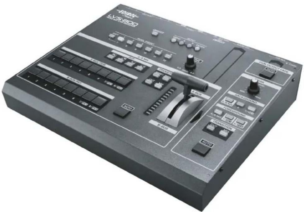
LVS-800 itself
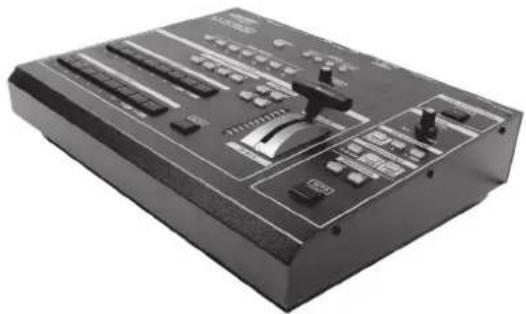
natural_image
Black industrial audio workstation with control knobs and buttons (no visible text or labels)AC Adaptor (PSB-7U) and Power Cord
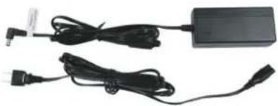
natural_image
Two black cables and a rectangular electronic device with connectors, shown against a white background (no text or symbols visible)RCA-BNC adaptor plugs (four)
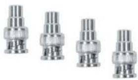
natural_image
Four identical metallic connectors with threaded leads, arranged in a row (no text or symbols visible)Owner's Manual (this document)

Top Panel
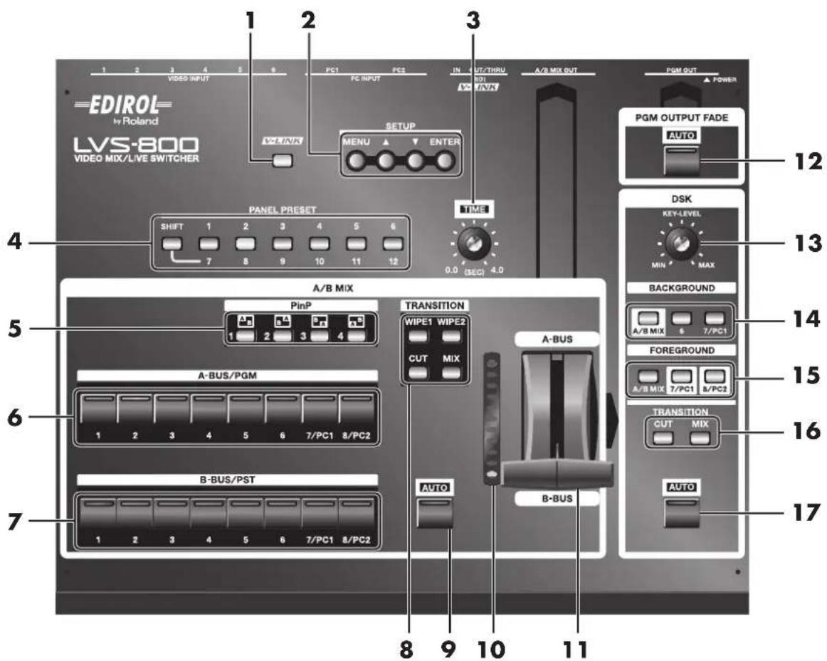
1. V-LINK Button
This allows connection of V-LINK-compatible equipment from Roland. To operate the RSS-V-Mixer by remote control, press this button to switch it on.
What's V-LINK?
V-LINK is a feature for performing video synchronized to music using MIDI. The V-LINK feature provides a quick and simple way to establish a link with a Roland instrument, music-production device, or video presenter.
MEMO
During remote control of a V-LINK-compatible instrument, music-production device, or video equipment via a MIDI connection, this button lights up automatically when V-LINK is switched on at the connected device.
MEMO
For more information about remote control via MIDI, V-LINK, or the RS-232C interface, please download the separately available reference document from the following Roland website.
http://www.rolandsystemsgroup.net/
2. SETUP Buttons (p. 36)
These are used for such tasks as displaying various menu items and making system settings.
3. TIME Dial
This sets the transition time when performing a switch using the AUTO button. It makes the following three AUTO-button time settings.
- For A/B MIX
- For DSK
•For PGM OUTPUT FADE
4. PANEL PRESET Buttons (p. 31)
These save the current panel settings. Use them to instantly call up saved panel settings.
5. PinP Buttons (p. 22)
These are used for Picture-in-Picture composition of the A Bus video and B Bus video.
6. A Bus/PGM Input Selectors (p. 16)
These select the video to input to A Bus.
*During use in the PGM-PST mode, you use these to select the video channel for program output.
7. B Bus/PST Input Selectors (p. 16)
These select the video to input to B Bus.
*During use in the PGM-PST mode, you use these to select the video for preview output.
8. TRANSITION Buttons for A/B MIX (p. 16)
These select the transition effect used during a transition between A Bus and B Bus.
9. AUTO Button for A/B MIX (p. 18)
This performs a transition between A Bus and B Bus by button operation, without using the video fader. It flashes during the transition operation. When the transition ends, it goes dark.
10. TRANSITION Indicator
This displays the location of the video fader. The lighted location is changed by operation of the video fader or the AUTO button for A/B MIX. Illumination of more elements toward the front of the unit indicates a greater ratio of B Bus video. Illumination of more elements toward the back of the unit indicates a greater ratio of A Bus video.
11. Video Fader (p. 17)
This is a T-bar type video fader. You switch between A Bus and B Bus by moving it up and down.
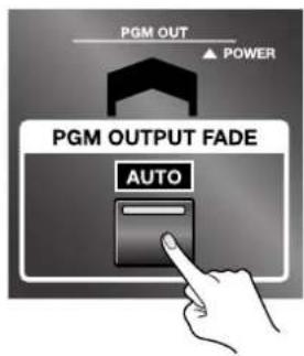
12. PGM OUTPUT FADE Button (p. 30)
Operating this button automatically applies a fade-in or fade-out to program output. The time of the fade-in or fade-out is set using the TIME dial. This lights up when a fade-out has been completed. It goes dark when a fade-in has been completed and program video is being output. It flashes while a fade is in progress.
This adjusts the degree of the key composition.
14. BACKGROUND Buttons (p. 27)
These select the DSK background picture.
15. FOREGROUND Buttons (p. 27)
These select the DSK foreground picture.
16. TRANSITION Buttons for DSK (p. 27)
These select how the picture set for the foreground to appear and disappear.
17. AUTO Button for DSK (p. 28)
This displays the picture set for the foreground. It lights up when the foreground picture is output. It goes dark when the picture is not output. It flashes while a mix is in progress.
Rear Panel
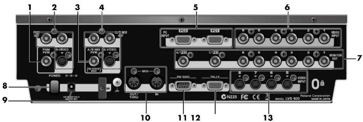
1. PGM PVW Connector
This outputs the DSK preview picture. Before performing DSK composition, you connect a monitor to check and verify the video displayed as the DSK foreground. You can then composite the background picture after first checking the logos, text, or other images.
2. PGM OUT Connectors
These output the mixed video plus the DSK composition. You connect them to projectors or other display equipment for the final output.
Two composite connectors and one S-Video connector are available. All connectors output the same picture.
3. A/B MIX PVW Connector
This outputs a preview picture for the video mix. You connect a monitor for previewing a source prior to committing to a transition. The current location of the video fader and the selected video on the inactive bus are output.
A variety of setting menus are also displayed at the top of the preview picture.
4. A/B MIX OUT Connectors
These output only the mix results for A Bus and B Bus. You can connect a video deck or other such recording unit and record the video prior to DSK composition.
Two composite connectors and one S-Video connector are available. All connectors output the same picture.
5. PC INPUT Connectors
These are for RGB-signal input. You can connect computers that serve as video source.
*Incoming computer signal will be downscalled to match the resolution of other video sources.
6. VIDEO INPUT (Composite) Connectors
These are for composite-signal input. You can connect cameras or other video sources.
7. MONITOR OUT Connectors
These output signals being input via the VIDEO INPUT connectors (composite or S-Video) without processing. You can connect a monitor to each of these "loop-thru" monitor outputs.
8. POWER Button
This switches the power on and off.
9. AC Adapter Connector
This is for connecting the included AC adapter (PSB-7U).
10. MIDI IN and OUT/THRU Connectors
Use these when connecting a MIDI device (a V-LINK-compatible product or the like) to operate the unit remotely, or when using the unit to perform remote control of another device.
11. RS-232C Connector
Use this when connecting an external device to operate the unit remotely.
MEMO
For more information about remote control via MIDI, V-LINK, or RS-232C interface, please download the separately available reference materials from the following Roland website. http://www.rolandsystemsgroup.net/
12. TALLY Connector
Provides low-current contact closure to activate tally lamps on your cameras or tally light system.
13. VIDEO INPUT (S-Video) Connectors
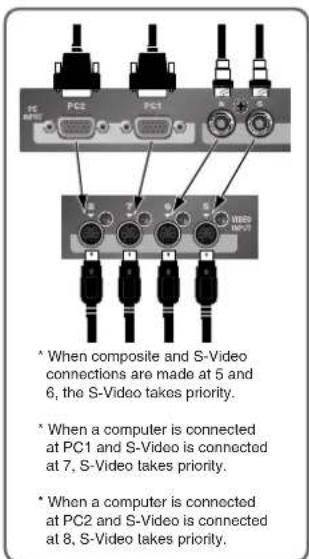
These are for input of S-Video signals. You can connect cameras or other video sources. When composite or RGB and S-Video signals are simultaneously input to the same channel, the S-Video signals take priority.
Connecting Source Devices
To prevent malfunction or damage to video monitors or other devices, always turn off the power on all devices before making any connections.
Connecting Video Devices
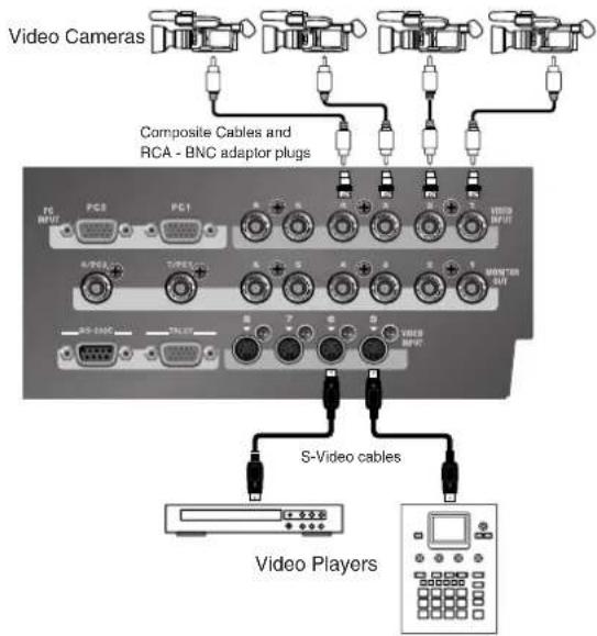
Channels 1 through 4 are exclusively for composite signals. S-Video can be connected to channels 5 through 8. Channels 5 and 6 can be used either for composite or S-Video, but S-Video takes priority when both types of signals are input.
*When connecting a device that has an RCA pin type connector to a composite input connector, use the included adapter plug.
Connecting Computers
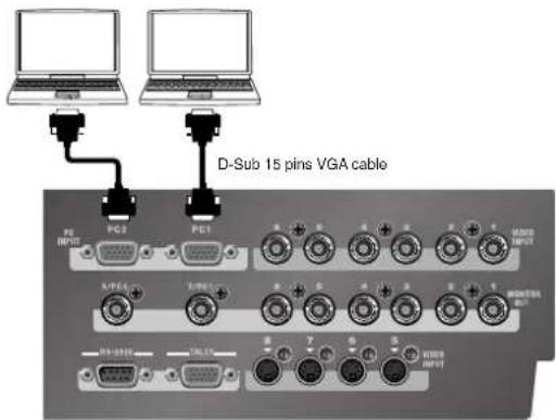
Computers can be connected at the PC1 and PC2 connectors. A built-in scan converter converts the incoming RGB signal to a standard definition video signal. Channels 7 and 8 can be used for both computer and S-Video input. When both types of signals are input, the S-Video takes priority.
*The PC1 and PC2 input connectors on the LVS-800 are for D-Sub 15-pin cables. Using a cable adapter makes it possible to connect devices that have DVI-I output connectors. A D-Sub 15-pin to DVI-I adapter is not included. Please purchase one separately.
Supported Resolutions
| 640 x 480 / 120Hz | 800 x 600 / 120Hz |
| 832 x 624 / 75Hz | 1024 x 768 / 80Hz |
| 1152 x 864 / 75Hz | 1152 x 870 / 75Hz |
| 1280 x 1024 / 75Hz | 1600 x 1200 / 60Hz |
* The refresh rate is the maximum value of each resolution.
NOTE
When displaying a movie from computer input, flicker or other picture corruption may occur. This is called tearing, and does not indicate an equipment malfunction.
Connecting Output Devices
The Difference Between A/B MIX OUT and PGM OUT
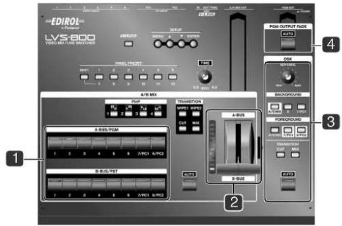
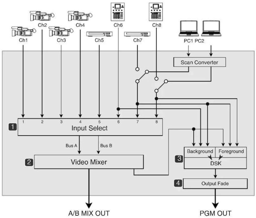
The LVS-800 is equipped with two sets of output connectors. These are the A/B MIX OUT connectors and the PGM OUT connectors. The A/B MIX OUT connectors output only the results of the mixed video of A Bus and B Bus (A/B MIX). The PGM OUT connectors output the results of the A/B mix plus your composited logos, text, etc (DSK composition). Final output fade is enabled only for PGM OUT.
*In the figure shown below, 1 through 4 indicate where on the panels the respective internal blocks are located.
flowchart
graph TD
    A["Input Select"] --> B["Video Mixer"]
    B --> C["A/B MIX OUT"]
    B --> D["PGM OUT"]
    E["Ch1 Ch2 Ch3 Ch4 Ch5 Ch6 Ch7 Ch8 PC1 PC2"] --> F["Scan Converter"]
    F --> G["Background"]
    F --> H["Foreground"]
    G --> I["DSK"]
    H --> I
    I --> J["Output Fade"]
    style A fill:#f9f,stroke:#333
    style E fill:#f9f,stroke:#333
    style F fill:#ccf,stroke:#333
    style G fill:#cfc,stroke:#333
    style H fill:#cfc,stroke:#333
    style I fill:#fcc,stroke:#333
    style J fill:#fcc,stroke:#333
Connecting Output Devices
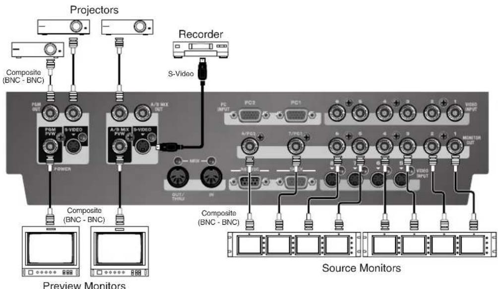
You can connect displays or capture devices to the A/B MIX OUT in order to view or capture the output of the A/B mix only (no DSK). You should connect displays or capture devices to the PGM OUT jacks in order to view or capture the final mix of A/B mix plus DSK. You can connect source monitors to the MONITOR OUT jacks to have at-a-glance monitoring of all your input sources. Monitors connected to the A/B MIX PVW or PGM PVW jacks will allow you to preview sources.
*When computers are connected to the PC1 and PC2 input connectors, the scan-converted video signals are output from the 7/PC1 and 8/PC2 output connectors.
*The output from A/B MIX PVW displays on-screen menu items in addition to the video before transition.
TALLY Output
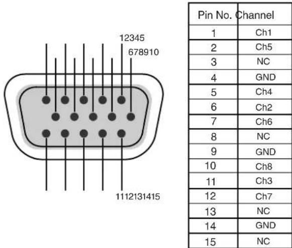
The LVS-800 is equipped with a D-Sub 15-pin TALLY output connector. Connecting a video monitor capable of tally input to this makes it possible to illuminate the tally lamps on the monitor. The lamp is switched on and off according to the channel selection, enabling you to see which channel is currently in use on the monitor.
The pin assignment is as shown below. The LVS-800 uses an open-collector tally output (closed contact).
*Connecting a video monitor capable of tally input requires a cable that must be obtained separately.
Connecting the AC adaptor
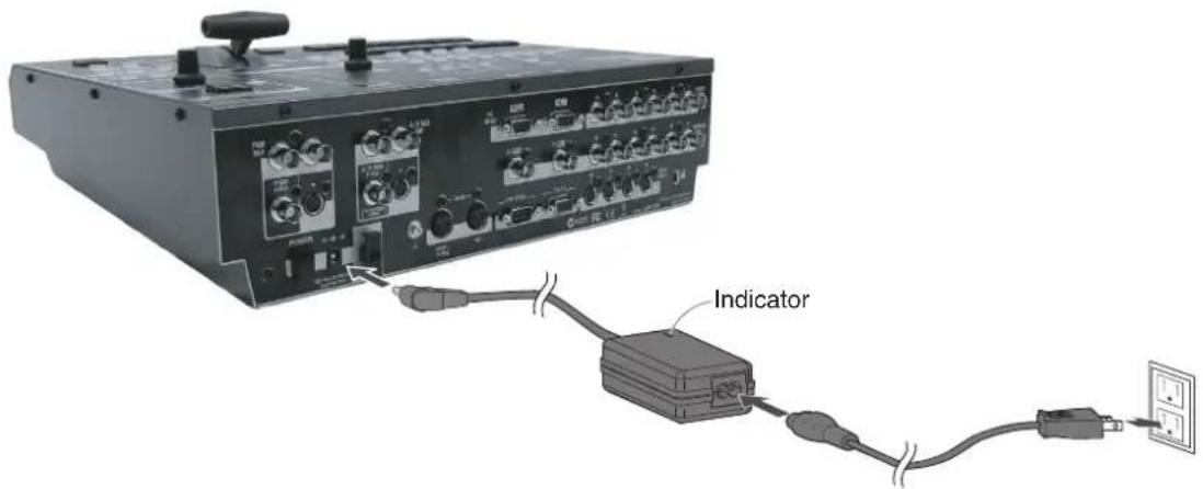
Connect the AC adaptor to LVS-800. Place the AC adaptor so the side with the indicator (see illustration) faces upwards and the side with textual information faces downwards. The indicator will light when you plug the AC adaptor into an AC outlet.
About Cord Hook
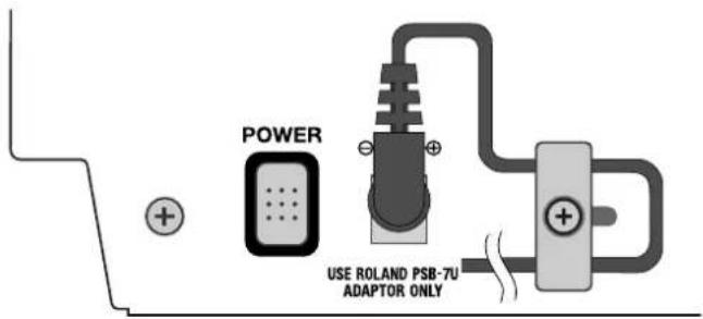
To prevent the inadvertent disruption of power to your unit (should the plug be pulled out accidentally), and to avoid applying undue stress to the AC adaptor connector, anchor the power cord using the cord hook, as shown in the illustration.
Caution regarding the power supply
Depending on the circumstances of a particular setup, you may experience a discomforting sensation, or perceive that the surface feels gritty to the touch when you touch this device, cameras connected to it, or the metal portions of other objects, such as VCRs. This is due to an infinitesimal electrical charge, which is absolutely harmless. However, if you are concerned about this, connect the ground terminal (see figure) with an external ground. When the unit is grounded, a slight noise may occur, depending on the particulars of your installation. If you are unsure of the connection method, contact the nearest Roland Service Center, or an authorized Roland distributor, as listed on the "Information" page.

Unsuitable places for connection
• Water pipes (may result in shock or electrocution)
•Gas pipes (may result in fire or explosion)
- Telephone-line ground or lightning rod (may be dangerous in the event of lightning)
Turning the power on
*Once the connections have been completed (p. 14), turn on power to your various devices in the order specified. By turning on devices in the wrong order, you risk causing malfunction and/or damage to monitors and other devices.
*This unit is equipped with a protection circuit. A brief interval (a few seconds) after power up is required before the unit will operate normally.
Turning the power on
Make sure that the AC adaptor is correctly connected. Press the [POWER] button located on rear panel. It takes few seconds to boot the system.
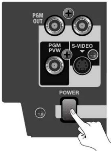
Turning the power off
Press the [POWER] button located on rear panel. Check all indicators/LEDs to turn off.
Switching Between A Bus and B Bus
Input sources are selected and switched between the A Bus and the B Bus. The unit has eight input selectors for each Bus, and you choose the input video for each bus before you perform the transition.
With the LVS-800, you can switch between A Bus and B Bus in three different modes. Operation of each of these modes is described below.
- A/B mode This performs switching using the video fader or the [AUTO] button for A/B MIX.
- PGM-PST mode This lets you check the preview picture before switching and perform the transition using the [AUTO] button.
• LVS mode This lets you perform switching directly, using only the input selector buttons.
The results of these operations are output from the A/B MIX OUT connectors. If you want to output the results from the PGM OUT connectors as well, make the settings described below.
- At [PGM OUTPUT FADE], switch off the [AUTO] button.
- At DSK, for [BACKGROUND], select [A/B MIX].
- Switch off the [AUTO] button for DSK.
Switching the Picture in the A/B Mode
Switching the Picture Using the Video Fader
1. Choose the A Bus and B Bus video.
Select the channels of the video input to A Bus and B Bus. Selecting an input channel makes the LED for the button light up. For information about what the color of the LED means, see the following page.
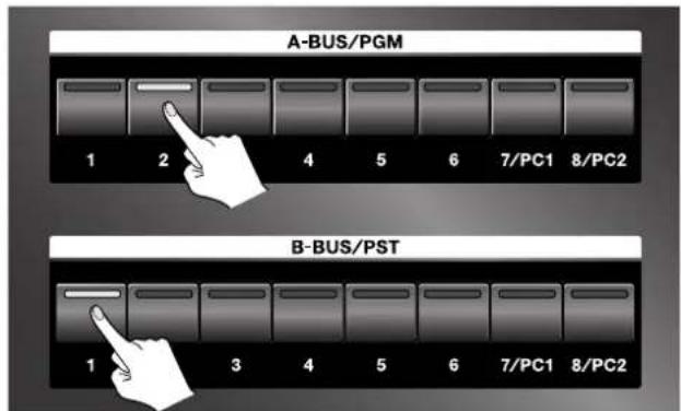
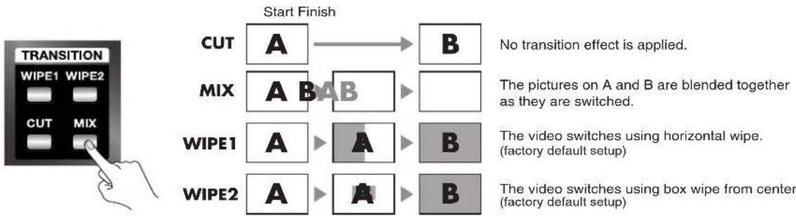
2. Choose the type of transition (transition effect).
If you want to apply a transition effect, use a [TRANSITION] button to choose [MIX], [WIPE1], or [WIPE2]. To apply no effect, choose [CUT].
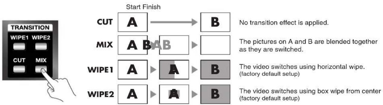
flowchart
graph TD
    A["Start Finish"] --> B["CUT"]
    B --> C["A"]
    C --> D["B"]
    E["MIX"] --> F["A"]
    F --> G["B"]
    G --> H["The images on A and B are blended together as they are switched."]
    I["WIPE1"] --> J["A"]
    J --> K["A"]
    K --> L["B"]
    M["WIPE2"] --> N["A"]
    N --> O["A"]
    O --> P["B"]
    Q["No transition effect is applied."] --> R["Factory default setup"]
    S["The video switches using box wipe from center (factory default setup)"] --> T["Factory default setup"]
3. Move the video fader.
Move the video fader. Moving it toward the back of the unit makes more of the picture on A Bus appear, and moving toward the front displays more B Bus picture.
*If you selected [CUT] in step 2, the picture is switched between A Bus and B Bus at the middle position of the video fader.
*When the same input channel has been selected for A Bus and B Bus, moving the video fader does not affect the output.
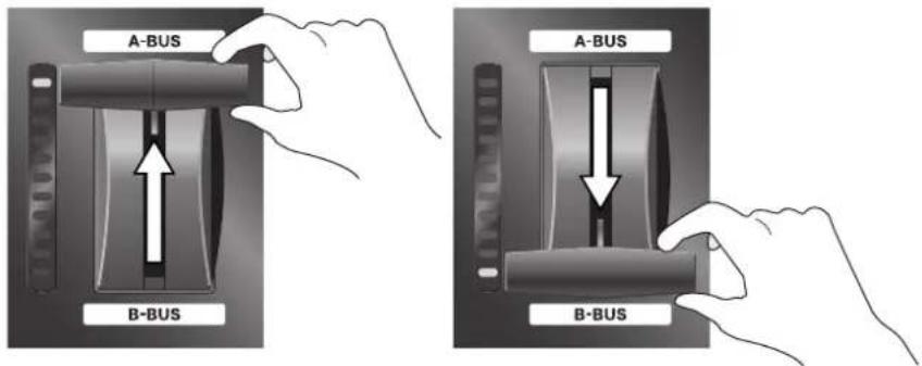
NOTE
When the video fader has not been moved all the way to the A Bus or B Bus side, changing the input channel for the opposite bus may cause noise on the output picture. When changing the input channel for the bus on the side opposite the bus displayed, first make sure that the video fader has been moved all the way to the end of the stroke.
The LEDs of the Input Selector Buttons
Pressing an input selector button for A Bus or B Bus makes the button's LED light up. The color of the LED may change to red or green, depending on the position of the video fader. The LED at the end of the stroke to which the video fader has been moved completely (100% output) lights up in red, and the LED at the opposite end of the stroke (corresponding to the channel now in standby and providing no output at all) lights up in green. When the control is not completely at one of these ends, and both buses are producing output, both LEDs light up in red.
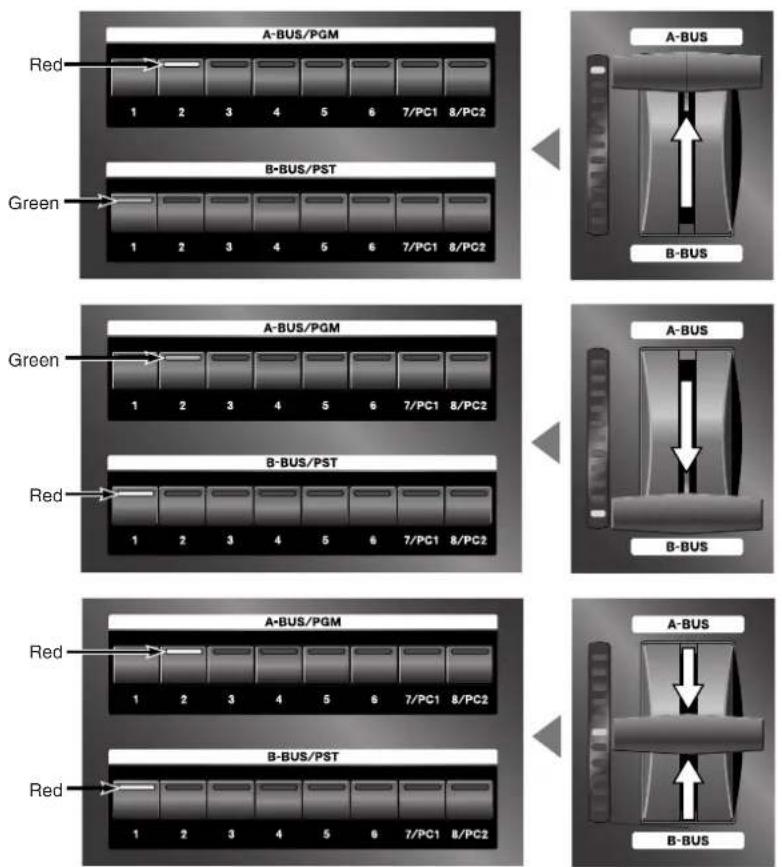
Switching Between A Bus and B Bus
Switching Using the AUTO Button
You can also perform switching simply by pressing the [AUTO] button for A/B MIX, without using the video fader. The video fader itself does not move, but movement between A and B is performed automatically. The location of the light on the TRANSITION indicator shows the movement between A and B.
1. Choose the type of transition (transition effect).
If you want to apply a transition effect, use a [TRANSITION] button to choose [MIX], [WIPE1], or [WIPE2]. To apply no effect, choose [CUT].
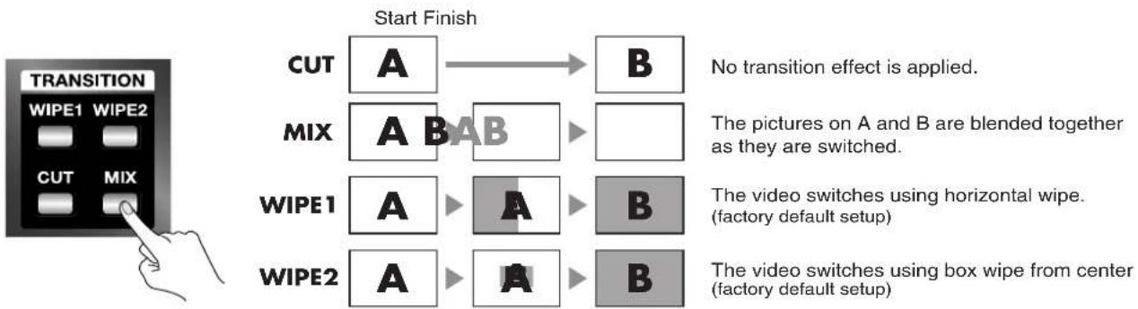
flowchart
graph TD
    A["Start Finish"] --> B["CUT"]
    A --> C["MIX"]
    A --> D["WIPE1"]
    A --> E["WIPE2"]
    B --> F["A"]
    C --> G["A"]
    D --> H["A"]
    E --> I["A"]
    F --> J["B"]
    G --> K["B"]
    H --> L["B"]
    style A fill:#f9f,stroke:#333
    style B fill:#ccf,stroke:#333
    style C fill:#ccf,stroke:#333
    style D fill:#ccf,stroke:#333
    style E fill:#ccf,stroke:#333
    note right of A: 'No transition effect is applied.'
    note right of G: 'The pictures on A and B are blended together as they are switched.'
    note right of L: 'The video switches using box wipe from center (factory default setup)'
2. Set the transition time.
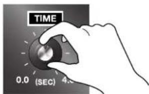
Turn the [TIME] dial to set the transition time. You can set this anywhere within the range of 0 (zero) to 4 seconds. You can set the transition time at any point along a stepless range.
*If you selected [CUT] in step 1, the time setting has no effect.
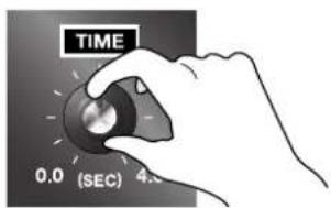
3. Perform the transition.
Press the [AUTO] button. The TRANSITION indicator shows the shift between A and B.
*When the same input channel has been selected for both A Bus and B Bus, no transition in the video occurs when the button is pressed.
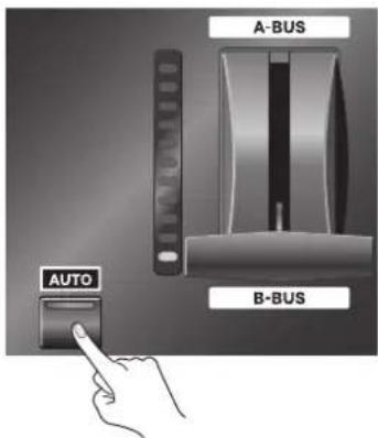
NOTE
When a transition has been made using the [AUTO] button, the position of the video fader does not match the lighted location of the TRANSITION indicator. Pulling the video fader back all the way toward the front may result in the indicator lighting up at the A Bus side.
A Bus is output in this status. To restore the original relation, move the video fader forward and backward all the way.
Use in Other Operation Modes Besides the A/B Mode
Changing the Operation Mode
Changing the operation mode is accomplished using the menus. For more information about how to do this, refer to "Changing Settings Using the Menus" (p. 36).
*The on-screen menu will only appear on a monitor connected to the A/B MIX PVW jack.
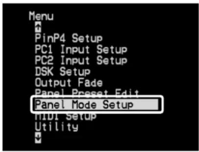
1. From the menu, select "Panel Mode Setup."
Press the [MENU] button to display the menu screen. From the list that appears, choose "Panel Mode Setup," then press the [ENTER] button.
2. Choose "PGM-PST Mode" or "LVS Mode."
- PGM-PST mode This lets you use the [AUTO] button for A/B MIX to execute a transition after checking the preview video.
- LVS mode This lets you perform a transition directly using the input selector buttons.
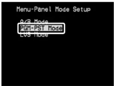
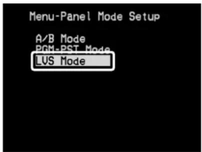
3. End the menu display.
Press the [MENU] button several times to make the menu display disappear.
The Names of the Buses in the PGM-PST Mode
When the operation mode is changed to the PGM-PST mode, the names of the buses also change. "A" becomes "PGM," and "B" becomes "PST."
Switching After Monitoring the Preview Picture (PGM-PST Mode)
In the PGM-PST mode, before you perform a switch, you can check the video on the preview monitor, then use the buttons to execute the transition. The preview picture is displayed on the preview monitor connected to the A/B MIX PVW connector.
1. Choose the type of transition (transition effect).
If you want to apply a transition effect, use a [TRANSITION] button to choose [MIX], [WIPE1], or [WIPE2]. To apply no effect, choose [CUT].
flowchart
graph TD
    A["Start Finish"] --> B["CUT"]
    A --> C["MIX"]
    A --> D["WIPE1"]
    A --> E["WIPE2"]
    B --> F["A"]
    C --> G["A"]
    D --> H["A"]
    E --> I["A"]
    F --> J["B"]
    G --> K["B"]
    H --> L["B"]
    style A fill:#f9f,stroke:#333
    style B fill:#ccf,stroke:#333
    style C fill:#ccf,stroke:#333
    style D fill:#ccf,stroke:#333
    style E fill:#ccf,stroke:#333
    note right of A: "No transition effect is applied."
    note right of G: "The pictures on A and B are blended together as they are switched."
    note right of L: "The video switches using box wipe from center (factory default setup)"
2. Set the transition time.
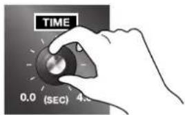
Turn the [TIME] dial to set the transition time. You can set this anywhere within the range of 0 (zero) to 4 seconds. You can set the transition time at any point along a stepless range.
*If you selected [CUT] in step 1, the time setting has no effect.
3. Choose the video channel on the PST side.
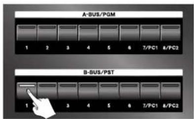
The picture on the selected channel is output to the preview monitor connected to the A/B MIX PVW connector. The selected video is not output to A/B MIX OUT or PGM OUT at this stage.
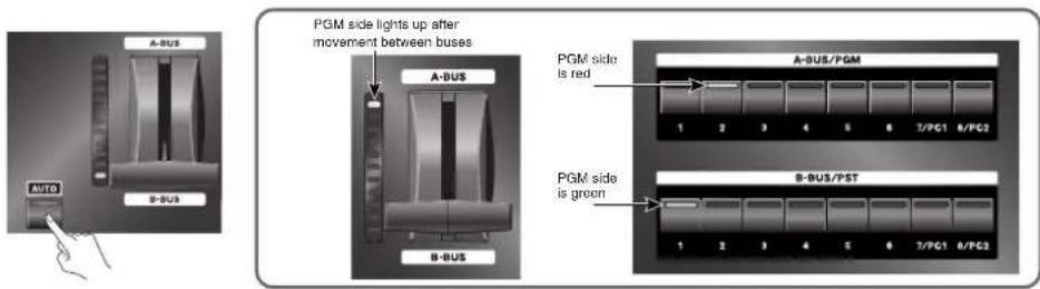
Press the [AUTO] button for A/B MIX. The video you selected in step 3 is output from the A/B MIX OUT and PGM OUT connectors. As this happens, the corresponding input LED is lit on the PGM Bus to indicate that the selected input is now active. PGM Bus will always indicate the currently active input being sent to the PGM outputs. In the PGM-PST mode, the TRANSITION indicator and the button LEDs work as shown below.
Switching the Picture Directly (LVS Mode)
When no previewing is needed, you can perform switching by using only the input selector buttons. This lets you execute a transition more easily and rapidly. You can do this in the LVS mode.
MEMO
In the LVS mode, B Bus is handled as main video and A Bus is handled as insert video. Moving the video fader to the A Bus side superimposes the insert video selected on A Bus over the main video of B Bus. P in P (Picture-in-Picture) settings are also enabled.
MEMO
The video selected for A Bus is output from the A/B MIX PVW connector.
- Move the video fader to the B Bus side.
- Select the input channel.
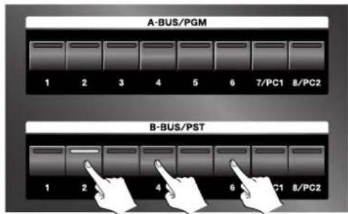
Press the B Bus input selector buttons in succession to switch the video.
*The transition-effect and transition-time settings remain in effect for switching performed in this way. Also note that no channel can be selected for A Bus while a transition effect is being applied.
NOTE
When the LVS mode is enabled and the video fader is set to A Bus, using the B Bus input selector buttons to switch the channel makes the output video change in the sequence shown below.
- Selected channel on A Bus
2.Previously selected channel on B Bus - Newly selected channel on B Bus
*At step 2, the picture is displayed briefly, then immediately changes to 3.
*Between 1 and 2, the transition-effect and transition-time settings have no effect.
*between 2 and 3, the transition-effect and transition-time settings are applied.
Let's say that you have selected input 2 on A Bus and input 1 on B Bus, and the video fader is set to A Bus. In this state, the video for input 2 is output. If you now change the selected channel for B Bus from input 1 to input 3, the output picture changes in the sequence shown below.
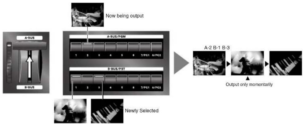
flowchart
graph LR
    A["Input Image"] --> B["Add Data to A-BUS"]
    B --> C["Add Data to B-BUS"]
    C --> D["Add Data to A-BUS/PGM"]
    D --> E["Add Data to B-BUS/PST"]
    E --> F["Add Data to A-2 B-1 B-3"]
    F --> G["Output only momentarily"]
    G --> H["Add Data to B-3"]
    H --> I["Newly Selected"]
    style A fill:#f9f,stroke:#333
    style B fill:#ccf,stroke:#333
    style C fill:#cfc,stroke:#333
    style D fill:#fcc,stroke:#333
    style E fill:#cff,stroke:#333
    style F fill:#ffc,stroke:#333
    style G fill:#fcf,stroke:#333
    style H fill:#cff,stroke:#333
    style I fill:#ffc,stroke:#333
Using Picture-in-Picture to Composite Two Screens
You can apply Picture-in-Picture to create a small window of one source superimposed over another source.
Composition in the A/B Mode or LVS Mode
The A Bus video is the inset screen, and is displayed over the B Bus video (the background).
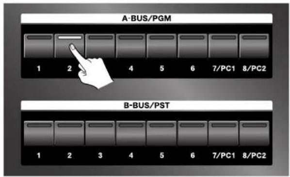
1. Choose the picture to display in the inset screen.
Choose the channel of the video to display in the inset screen on A Bus.
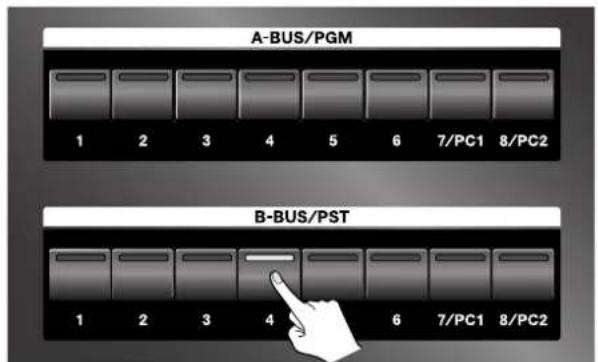
2. Choose the picture to make the background.
Choose the channel of the video for the background on B Bus.
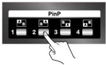
3. Press a [P in P] button.
Press any of the four [PinP] buttons. The location where the inset screen is displayed varies depending on the button you press.
The [A] in the square on the panel indicates the location of the inset screen.
MEMO
Pressing the illuminated [PinP] button a second time cancels the selection and makes the button go dark. The picture on the inset screen displayed changes to a full-screen display.
Switching Between A Bus and B Bus
4. Move the video fader to the A Bus (inset screen) side.
Move the video fader to the A Bus side. The inset screen appears.
*The way the inset screen comes into view differs according to the transition-effect setting. When [CUT] has been selected, it remains hidden until the middle position is reached, and is displayed thereafter.
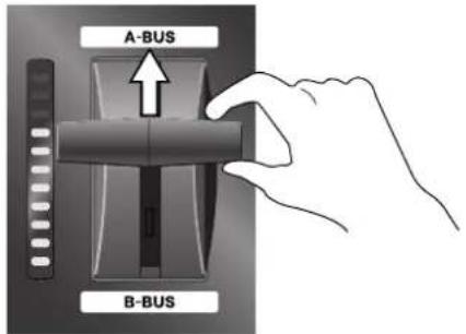
5. Move the video fader to the B Bus (background) side.
Move the video fader to the B Bus side. The inset screen disappears.
*The way the inset screen disappears from view differs according to the transition-effect setting.
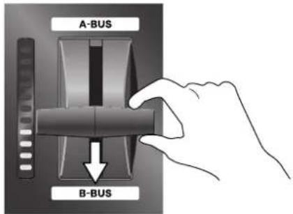
TIP
You can apply Picture-in-Picture by using the [AUTO] button for A/B MIX, without operating the video fader.
TIP
You can also change where the inset screen is displayed while Picture-in-Picture is being applied. Pressing a different [P in P] button from the one you chose in step 3 changes the display location.
NOTE
In the LVS mode, using a B Bus input selector to change the background picture during display of an inset screen makes the displayed inset screen disappear. If this happens, move the video fader to the B Bus side, then move it back to the A Bus side. Returning it to the A Bus side makes the inset screen reappear.
In the A/B mode, changing the background does not make the displayed inset screen disappear.
NOTE
The only transition effects available for selection during Picture-in-Picture composition are [MIX] and [CUT]. Selecting [WIPE1] or [WIPE2] is not possible.
Switching Between A Bus and B Bus
Composition in the PGM-PST Mode
You can use Preview to check the video for inset-screen display first, then display it using the [AUTO] button.
1. Choose the background channel.
Choose the channel of the video to display as the background with PST.
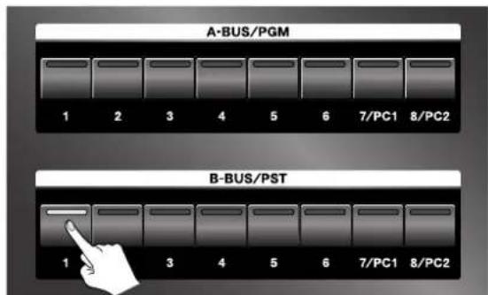
2. Display the background.
Press the [AUTO] button to display the background video.
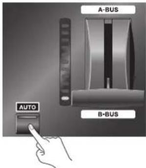
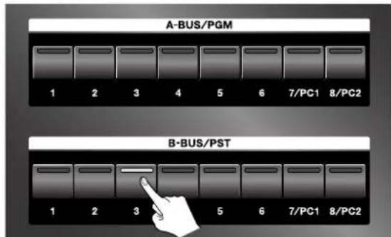
3. Check the picture of the inset screen.
Choose the channel of the video to display in the inset screen with PST. The selected picture is output to the preview monitor connected to the A/B MIX PVW connector.
Switching Between A Bus and B Bus
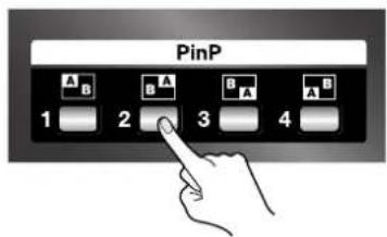
4. Press a [P in P] button.
Press any of the four [PinP] buttons. The location where the inset screen is displayed varies depending on the button you press. The [A] in the square on the panel indicates the location of the inset screen.
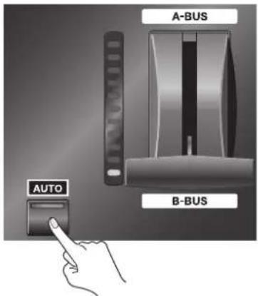
5. Display the inset screen.
Press the [AUTO] button for A/B MIX to composite the inset-screen picture on the background. The results of composition are output to a recording unit or projector connected to a A/B MIX OUT connector.
*The way the inset screen comes into view differs according to the transition-effect setting. When |CUT| has been selected, it appears instantly when the [AUTO] button for / B MIX is pressed.
6. Make the inset screen disappear.
Press the [AUTO] button for A/B MIX to make the inset-screen picture disappear.
*The way the inset screen disappears from view differs according to the transition-effect setting. When [CUT] has been selected, it disappears instantly when the [AUTO] button for A/B MIX is pressed.
TIP
You can also change where the inset screen is displayed while Picture-in-Picture is being applied. Pressing a different [PinP] button from the one you chose in step 3 changes the display location.
What's a Downstream Keyer (DSK)?
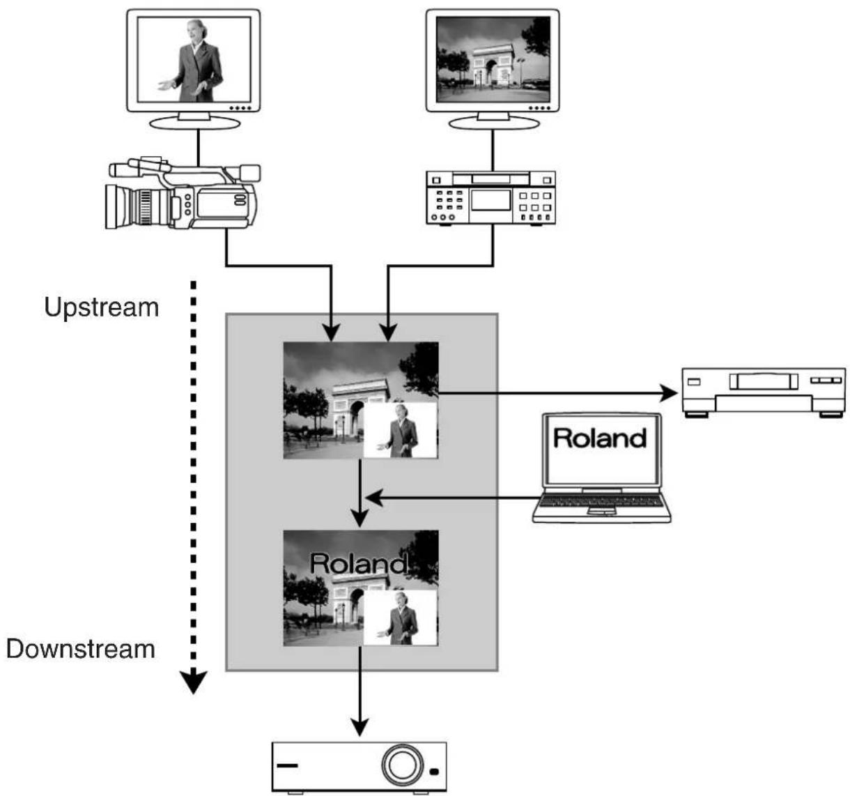
A Downstream Keyer (DSK) allows you to superimpose text or graphics over background video. Since the text of graphics appear "downstream" from your A/B mix, you can freely switch or mix various video sources behind your "keyed" text or graphics.
Generally, elements such as logos and text are composited using DSK. This feature makes it possible to switch the background video or actuate picture-in-picture while displaying same logos or text in the foreground.
NOTE
The results of DSK composition are output only via the PGM OUT connectors. No DSK output comes from the A/B MIX OUT connectors.
flowchart
graph TD
    A["Upstream"] --> B["Camera"]
    C["Downstream"] --> D["Radio"]
    B --> E["Monitor 1"]
    B --> F["Monitor 2"]
    B --> G["Monitor 3"]
    B --> H["Monitor 4"]
    B --> I["Monitor 5"]
    B --> J["Monitor 6"]
    B --> K["Monitor 7"]
    B --> L["Monitor 8"]
    B --> M["Monitor 9"]
    B --> N["Monitor 10"]
    B --> O["Monitor 11"]
    B --> P["Monitor 12"]
    B --> Q["Monitor 13"]
    B --> R["Monitor 14"]
    B --> S["Monitor 15"]
    B --> T["Monitor 16"]
    B --> U["Monitor 17"]
    B --> V["Monitor 18"]
    B --> W["Monitor 19"]
    B --> X["Monitor 20"]
    B --> Y["Monitor 21"]
    B --> Z["Monitor 22"]
    B --> AA["Monitor 23"]
    B --> AB["Monitor 24"]
    B --> AC["Monitor 25"]
    B --> AD["Monitor 26"]
    B --> AE["Monitor 27"]
    B --> AF["Monitor 28"]
    B --> AG["Monitor 29"]
    B --> AH["Monitor 30"]
    B --> AI["Monitor 31"]
    B --> AJ["Monitor 32"]
    B --> AK["Monitor 33"]
    B --> AL["Monitor 34"]
    B --> AM["Monitor 35"]
    B --> AN["Monitor 36"]
    B --> AO["Monitor 37"]
    B --> AP["Monitor 38"]
    B --> AQ["Monitor 39"]
    B --> AR["Monitor 40"]
    B --> AS["Monitor 41"]
    B --> AT["Monitor 42"]
    B --> AU["Monitor 43"]
    B --> AV["Monitor 44"]
    B --> AW["Monitor 45"]
    B --> AX["Monitor 46"]
    B --> AY["Monitor 47"]
    B --> AZ["Monitor 48"]
    B --> BA["Monitor 49"]
    B --> BB["Monitor 50"]
    B --> BC["Monitor 51"]
    B --> BD["Monitor 52"]
    B --> BE["Monitor 53"]
    B --> BF["Monitor 54"]
    B --> BG["Monitor 55"]
    B --> BH["Monitor 56"]
    B --> BI["Monitor 57"]
    B --> BJ["Monitor 58"]
    B --> BK["Monitor 59"]
    B --> BL["Monitor 60"]
    B --> BM["Monitor 61"]
    B --> BN["Monitor 62"]
    B --> BO["Monitor 63"]
    B --> BP["Monitor 64"]
    B --> BQ["Monitor 65"]
    B --> BR["Monitor 66"]
    B --> BS["Monitor 67"]
    B --> BT["Monitor 68"]
    B --> BU["Monitor 69"]
    B --> BV["Monitor 70"]
    B --> BW["Monitor 71"]
    B --> BX["Monitor 72"]
    B --> BY["Monitor 73"]
    B --> BZ["Monitor 74"]
    B --> CA["Monitor 75"]
    B --> CB["Monitor 76"]
    B --> CC["Monitor 77"]
    B --> CD["Monitor 78"]
    B --> CE["Monitor 79"]
    B --> CF["Monitor 80"]
Trying Out DSK Composition
1. Choose the background picture.
Use the three BACKGROUND buttons to choose the background video. If you want to use the results of the A/B mix as the background, press the [A/B MIX] button to make it light up. If you want to use source video directly from channel 6 or channel 7 as the background, choose [6] or [7/PC1].
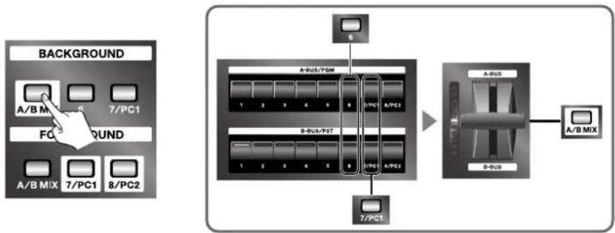
flowchart
graph TD
    A["BACKGROUND"] --> B["A/B MIX"]
    B --> C["7/PC1"]
    C --> D["FC"]
    D --> E["7/PC1"]
    E --> F["8/PC2"]
    G["6"] --> H["A-PU3/PGM"]
    H --> I["1 2 3 4 5 6 7/PC1"]
    I --> J["8-PU3/PST"]
    J --> K["1 2 3 4 5 6 7/PC1"]
    L["7/PC1"] --> M["A-PU3"]
    M --> N["D-PU3"]
    N --> O["A/B MIX"]
    style A fill:#f9f,stroke:#333
    style G fill:#f9f,stroke:#333
    style L fill:#f9f,stroke:#333
2. Choose the foreground picture.
Use the three FOREGROUND buttons to choose the video you want to composite and display on the foreground. If you want to composite a logo, text, or other such element from a computer, press either the [7/PC1] button or the [8/PC2] button to make it light up. The picture you selected using FOREGROUND is output to the preview monitor via the PGM PVW connector.
NOTE
Before you perform composition, check whether the picture from the computer is being output correctly to the LVS-800. Send the output from channels 7 or 8 to a monitor or projector, and check the picture. The output might not look correct if the proper settings have not been made on the computer.
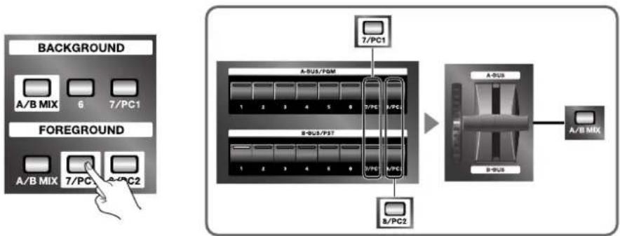
flowchart
graph TD
    A["BACKGROUND"] --> B["A/B MIX 6 7/PC1"]
    C["FOREGROUND"] --> D["A/B MIX 7/PC2"]
    E["7/PC1"] --> F["B-USB/PDM"]
    G["8/PC2"] --> H["B-USB/PST"]
    I["A-USB"] --> J["A/B MIX"]
    K["B-USB"] --> L["A/B MIX"]
3. Decide how the keyed material appears and disappears.
Decide how the picture you selected in step 2 to appears and disappears. Select either [CUT] or [MIX]. Selecting [CUT] makes the foreground picture appear and disappear instantly. Selecting [MIX] makes it fade in and fade out. You can set the time for the fade-in and fade-out (from 0 to 4 seconds) by turning the [TIME] dial.
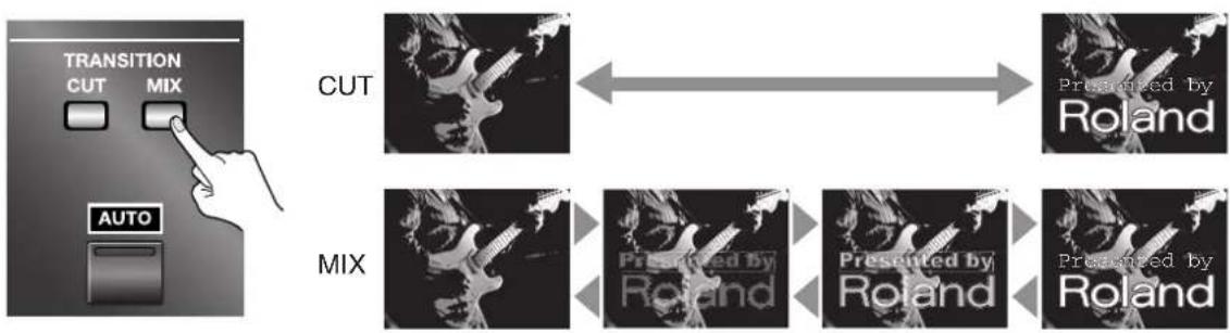
flowchart
graph LR
    A["TRANSITION CUT MIX"] --> B["CUT"]
    C["AUTO"] --> D["MIX"]
    E["Presented by Roland"] --> F["Presented by Roland"]
    G["Presented by Roland"] --> H["Presented by Roland"]
Using the Downstream Keyer (DSK)
4. Perform composition and output.
Pressing the [AUTO] button for DSK performs composition of the selected FOREGROUND picture superimposed on the selected BACKGROUND picture. The composited video is output to a projector or other device connected to the PGM OUT connectors.
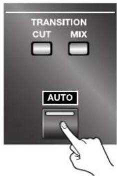
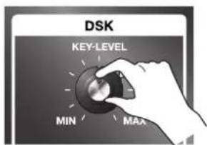
5. Adjust the key level.
You can adjust the key level by turning the [KEY LEVEL] dial. Turning it all the way to [MIN] makes no key composition at all, and outputs the FOREGROUND picture unchanged. At [MAX], keying is maximum, and only the BACKGROUND picture is output. Find the place where the key level is exactly right.
MEMO
By default, black is the key color used in key composition. Keyed material featuring white, yellow or brightly colored (non-dark) text or logos on a black background produces optimal "overlay" onto your background video. You can also use the menus to select a different color. Refer to "Changing Settings Using the Menus" (p. 36) and "Menu List" (p. 38).

MEMO
You can also add edge blur (soft edges) to text or logos displayed in the composited foreground. Edge blur can help reduce jagged, noisy edges on your key material. The degree of blur is set using the menus. Refer to "Changing Settings Using the Menus" (p. 36) and "Menu List" (p. 38).
TIP
You can also display the FOREGROUND picture as an inset screen using Picture-in-Picture, instead of using key composition. You use the menus to change the DSK mode. Refer to "Changing Settings Using the Menus" (p. 36) and "Menu List" (p. 38).
Combining DSK and Picture-in-Picture
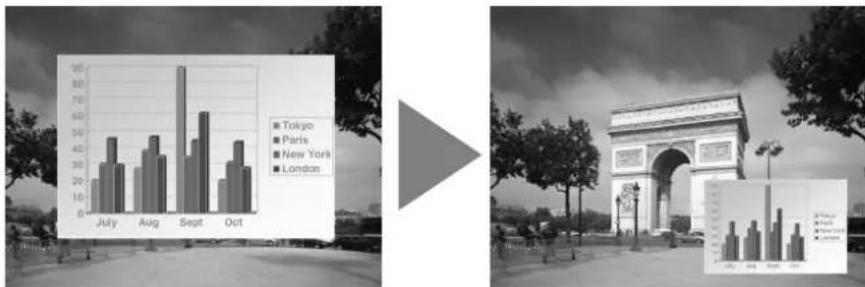
With the LVS-800, you can perform DSK composition, then also apply Picture-in-Picture (PinP). This lets you display logos or other elements in smaller size and at the place you want on the screen. For information on how to select the background and foreground video, refer to the previous section.
*When key composition and Picture-in-Picture are used in combination, the Border and Shadow settings assigned to PinP1 through PinP4 have no effect. Only the settings for location and size are effective.
Keyer only Keyer + PinP
bar
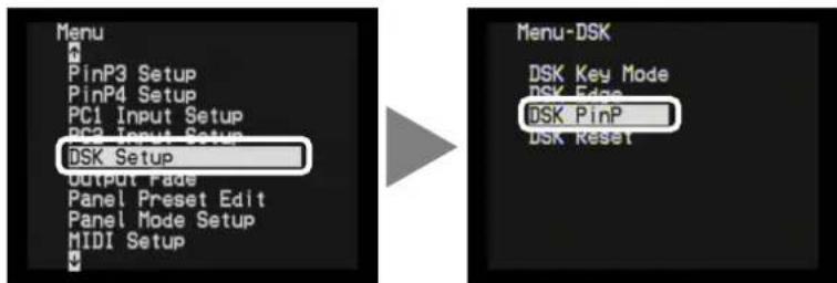
| Month | Tokyo | Paris | New York | London | |---|---|---|---|---| | July | 25 | 38 | 30 | 40 | | Aug | 30 | 42 | 35 | 38 | | Sept | 90 | 45 | 65 | 30 | | Oct | 20 | 35 | 40 | 30 |1. From the menu, select "DSK Setup" and "DSP PinP."
Press the [MENU] button to display the menu screen. From the list that appears, use UP or DOWN to highlight "DSK Setup," then press the [ENTER] button. From the list that appears, choose "DSK PinP." After making the selection, press the [ENTER] button.
*The on-screen menu will only appear on a monitor connected to the A/B MIX PVW jack.
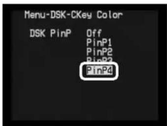
2. Decide on the P in P number.
By default, this is set to "Off." Choose the number from "PinP1" to "PinP4". After making the selection, press the [MENU] button three times to quit the menu display.
3. Perform composition and output.
Pressing the [AUTO] button for DSK reduces the size of the FOREGROUND picture according to the setting of PinP1 through PinP4, and performs composition of the FOREGROUND picture superimposed on the BACKGROUND picture.
4. Adjust the key level.
You can adjust the key level by turning the [KEY LEVEL] dial.
Applying Fade to the Final Output
You can apply fade-in or fade-out to the output from the PGM OUT connectors (the program output).
Pressing the [AUTO] button for PGM OUTPUT FADE makes the button's LED flash and starts a fade-out. When the fade-out has been completed, the button stops flashing and stays lit. Press the PGM OUTPUT FADE button again to start a fade-in. When the fade-in ends, the LED goes dark.
If you want to change the fade-in or fade-out time (to any value from 0 to 4 seconds), adjust it using the TIME dial.
MEMO
By default, black is the color used for fades. You can also use the menus to select white. Refer to "Changing Settings Using the Menus" (p. 36) and "Menu List" (p. 38).
You can save the state of various controls to [PANEL PRESET] buttons. Saving lets you call up a variety of settings at the press of a button. The [PANEL PRESET] buttons are numbered from 1 to 12, and let you save up to 12 sets of settings.
You can save the state of the controls described below.
| Items Parameters to save | ||
| A/B MIX Section | Bus A Input Selector Selected input channel | |
| Bus B Input Selector Selected input channel | ||
| PinP Button Selected PinP position (1-4) | ||
| TRANSITION Button Selected transition effect type | ||
| Video Fader Position between A and B * | ||
| DSK Section | BACKGROUND Button Background channel | |
| FOREGROUND Button Foreground channel | ||
| TRANSITION Button Appearance and disappearance of foreground | ||
| AUTO Button Output or non-output of foreground | ||
| KEY LEVEL Dial Level of keyer | ||
| DSK Key Mode Color of keyer | ||
| DSK PinP On/Off of DSK PinP and the position (1-4) | ||
| Others | TIME Dial Time of transition and PGM output fade | |
| PGM OUTPUT FADE Output or non-output of program picture | ||
*The internal position between A and B of the video fader is indicated by the lighted location of the TRANSITION indicator next to the video fader. This may not necessarily match the position of the video fader. To make these match up, move the video fader forward and backward all the way.
Saving the Current Settings
Follow the steps described below to save the current state.
1. Put the unit in the state you want to save.
Make the settings for the bus input channels, Picture-in-Picture, and other values.
2. Save the settings.
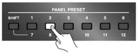
To save the settings to one of the [PANEL PRESET] buttons from 1 through 6, press and hold the button for three seconds or longer.
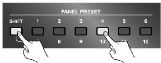
To save the settings to a button from 7 through 12, press the [SHIFT] button to make it light up, then press and hold the desired button for three seconds or longer.
When all [PANEL PRESET] buttons flash, the saving operation has finished.
1-6 7-12
Calling Up Saved Settings
To recall values that have been saved, press the button corresponding to the number you want to call up. The pressed button lights up and the saved values are recalled. Recalling settings in this way puts the various controls in the same state they were in when the settings were saved. The pressed button lights up while the recalled state remains in effect. If the called-up state is changed, the button goes dark.
*To call up values saved at a button from 7 through 12, press the [SHIFT] button, then press the numbered button.
Copying Saved Settings to Another Button
You can copy the settings saved from any Panel Preset button to another Panel Preset button. Use the menus to perform the copy operation. For information on how to use the menus, refer to "Changing Settings Using the Menus" (p. 36).
*To view the on-screen menu, you need to have a monitor connected to the A/B MIX PVW jack.
NOTE
Executing a copy operation overwrites any existing settings at the copy destination, causing any previously saved settings to be lost.
1. Display the menu.
Press the [MENU] button to display the menu.
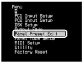
2. Select "Panel Preset Edit."
From the list that appears, choose "Panel Preset Edit," then press the [ENTER] button.
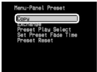
3. Select "Copy."
From the list that appears, choose "Copy," then press the [ENTER] button.
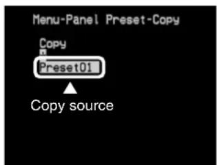
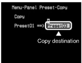
4. Select the numbers of the copy source and destination.
The number displayed on the left side of the screen is the copy source. Use the arrow buttons to select the number of the copy source, then press the [ENTER] button. Pressing this displays a number for the copy destination on the right side of the screen. Use the arrow buttons to select the number of the copy destination, then press the [ENTER] button.
5. Execute the copy operation.
To execute the copy operation, select "Yes [ENTER] SW" and press the [ENTER] button. To cancel execution, select "No" and press the [ENTER] button. When the operation has ended, press the [MENU] button several times to quit the menu display.
![Menu-Panel Preset-Copy Copy Preset01 ==> Preset03 No Yes [ENTER] SW](/content/2026/05/979765/images/1e451ab65b1acabc1c6e41d10b9432ce09cae9544cebfe775a01924925678170.jpg)
Exchanging Saved Settings with Another Button
You can exchange (swap) the settings saved at any button with the settings at another button. Use the menus to perform the exchange operation. For information on how to use the menus, refer to "Changing Settings Using the Menus" (p. 36).
1. Display the menu.
Press the [MENU] button to display the menu.
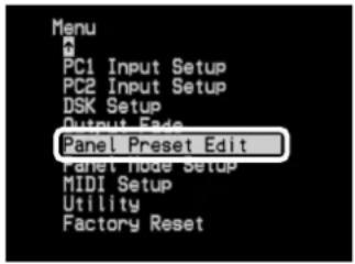
2. Select "Panel Preset Edit."
From the list that appears, choose "Panel Preset Edit," then press the [ENTER] button.
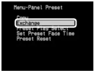
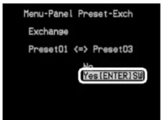
3. Select "Exchange."
From the list that appears, choose "Exchange," then press the [ENTER] button.
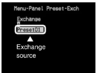
4. Select the numbers of the exchange source and destination.
The number displayed on the left side of the screen is the exchange source. Use the arrow buttons to select the number of the exchange source, then press the [ENTER] button. Pressing this displays a number for the exchange destination on the right side of the screen. Use the arrow buttons to select the number of the exchange destination, then press the [ENTER] button.
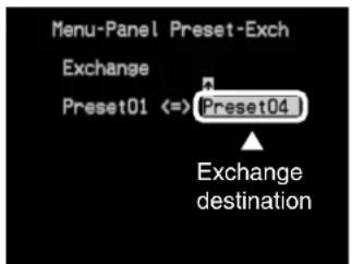
5. Execute the exchange operation.
To execute the exchange operation, select "Yes [ENTER] SW" and press the [ENTER] button. To cancel execution, select "No" and press the [ENTER] button. When the operation has ended, press the [MENU] button several times to quit the menu display.
This returns various settings to their factory defaults.
Executing a factory reset causes all settings and saved values except the following settings to be lost.
(Please be aware that settings saved to PANEL PRESET buttons are also lost.)
•NTSC/PAL setting (p. 35)
- Calibration of the video fader (Video Fader Calibrate A/B)
*To view the on-screen menu, you need to have a monitor connected to the A/B MIX PVW jack.
1. At the menu, choose "Factory Reset."
Press the [MENU] button to display the menu. From the list, choose "Factory Reset," then press the [ENTER] button.
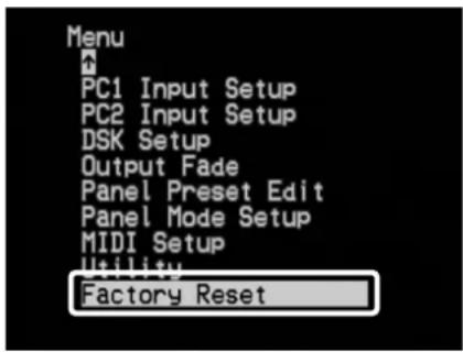
2. Choose "Yes [ENTER] SW."
Use the arrow buttons to choose "Yes [ENTER] SW."
![Menu-Factory Reset Are You Sure ? No Yes [ENTER] SW](/content/2026/05/979765/images/baf52367892a3dadc511f6beb2c16173d2877c4c106a7de98472064b5ab0793e.jpg)
3. Execute FACTORY RESET.
Pressing the [ENTER] button returns the unit to its factory-default state.
*Pressing the [MENU] button at this stage returns you to the previous screen without returning the unit to its factory-default state.
4. Quit the menu screen.
Press the [MENU] button several times to make the menu display disappear.
Switching Between NTSC and PAL
The LVS-800 can switch to NTSC or PAL at startup.
Switching to NTSC at Startup
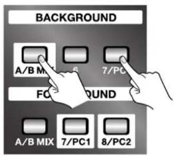
At the DSK section, under [BACKGROUND], hold down the [A/B MIX] and [7/PC1] buttons and turn on the power. Once set to NTSC, the setting persists in memory even after power off.
Switching to PAL at Startup
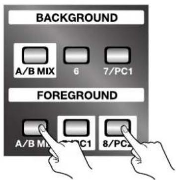
At the DSK section, under [FOREGROUND], hold down the [A/B MIX] and [8/PC2] buttons and turn on the power. Once set to PAL, the setting persists in memory even after power off.
You can also use the menus to switch between NTSC and PAL. At the "Utility" menu, choose "NTSC/PAL," then select "NTSC" or "PAL." After this operation, the setting requires some time to take effect.
Changing Settings Using the Menus
Making changes to various settings, including the operation mode and the location and size of the inset screen for Picture-in-Picture, are tasks you perform after first displaying the menus.
Displaying the Menus
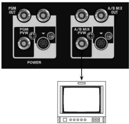
The menus are displayed in the preview monitor connected to the A/B MIX PVW connector. When you're performing menu operations, first be sure to connect a preview monitor.
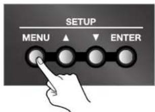
Pressing the [MENU] button displays the menu screen on the preview monitor.
Menu Levels
The menus are structured using the level hierarchy shown below. Selecting an upper-level item displays the lower level for setting the value.
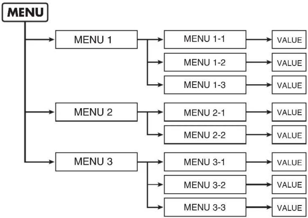
flowchart
graph TD
    A["MENU"] --> B["MENU 1"]
    A --> C["MENU 2"]
    A --> D["MENU 3"]
    B --> E["MENU 1-1"]
    B --> F["MENU 1-2"]
    B --> G["MENU 1-3"]
    E --> H["VALUE"]
    F --> I["VALUE"]
    G --> J["VALUE"]
    C --> K["MENU 2-1"]
    C --> L["MENU 2-2"]
    D --> M["MENU 3-1"]
    D --> N["MENU 3-2"]
    D --> O["MENU 3-3"]
    K --> P["VALUE"]
    L --> Q["VALUE"]
    M --> R["VALUE"]
    N --> S["VALUE"]
    O --> T["VALUE"]
Menu Operations
Use the procedure described below to change various settings.
1. Display the menu.
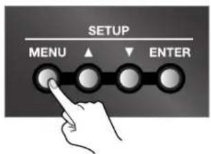
Go to SETUP and press the [MENU] button. The menu screen appears on the preview monitor.
2. Choose the item whose setting you want to change.
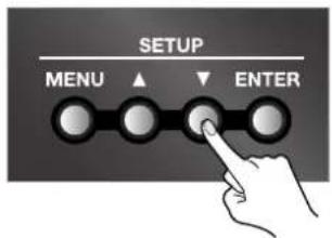
Use the up and down arrow buttons to choose the item whose setting you want to change.
3. Decide on the setting-change item.
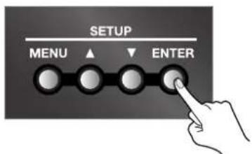
Press the [ENTER] button to move down one level.
*If the menu item is located at a deeper level, repeat steps 2 and 3.
*To go back to the original level, press the [MENU] button.
4. Change the setting value.
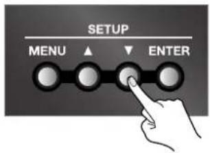
Use the up and down arrow buttons to change the setting value.
5. End the menu display.
Press the [MENU] button several times to make the menu display disappear.
MEMO
The values of menu settings are saved in internal memory when you exit the menu. To save the values of settings, exit the menu screen before you turn off the power.
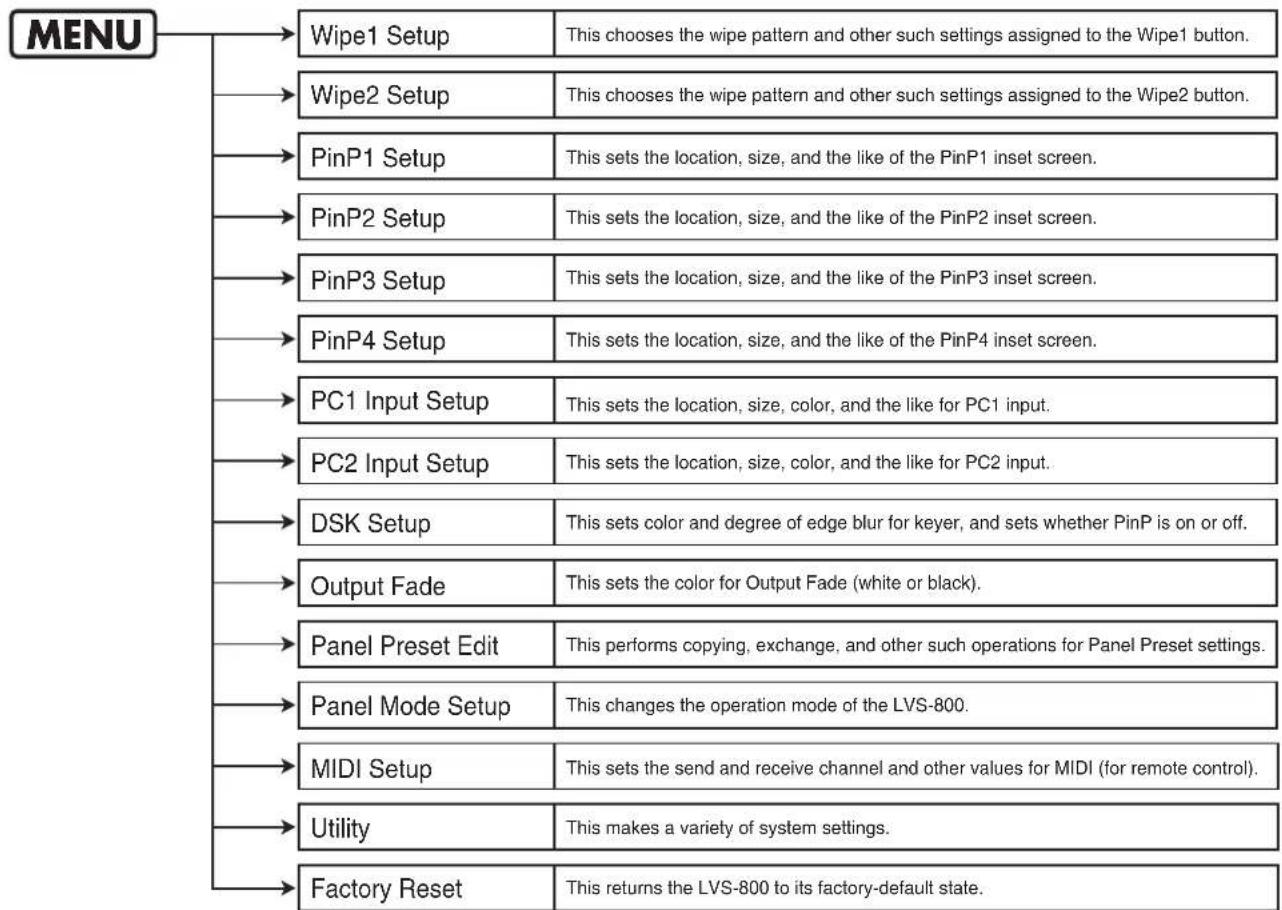
Going to SETUP and pressing the [MENU] button starts by displaying the menu items at the first level.
For information on the menu items at the second level, refer to the following pages.
flowchart
graph TD
    A["MENU"] --> B["Wipe1 Setup"]
    A --> C["Wipe2 Setup"]
    A --> D["PinP1 Setup"]
    A --> E["PinP2 Setup"]
    A --> F["PinP3 Setup"]
    A --> G["PinP4 Setup"]
    A --> H["PC1 Input Setup"]
    A --> I["PC2 Input Setup"]
    A --> J["DSK Setup"]
    A --> K["Output Fade"]
    A --> L["Panel Preset Edit"]
    A --> M["Panel Mode Setup"]
    A --> N["MIDI Setup"]
    A --> O["Utility"]
    A --> P["Factory Reset"]

    B --> Q["This chooses the wipe pattern and other such settings assigned to the Wipe1 button."]
    C --> R["This chooses the wipe pattern and other such settings assigned to the Wipe2 button."]
    D --> S["This sets the location, size, and the like of the PinP1 inset screen."]
    E --> T["This sets the location, size, and the like of the PinP2 inset screen."]
    F --> U["This sets the location, size, and the like of the PinP3 inset screen."]
    G --> V["This sets the location, size, and the like of the PinP4 inset screen."]
    H --> W["This sets the location, size, color, and the like for PC1 input."]
    I --> X["This sets the location, size, color, and the like for PC2 input."]
    J --> Y["This sets color and degree of edge blur for keyer, and sets whether PinP is on or off."]
    K --> Z["This sets the color for Output Fade (white or black)."]
    L --> AA["This performs copying, exchange, and other such operations for Panel Preset settings."]
    M --> AB["This changes the operation mode of the LVS-800."]
    N --> AC["This sets the send and receive channel and other values for MIDI (for remote control)."]
    O --> AD["This makes a variety of system settings."]
    P --> AE["This returns the LVS-800 to its factory-default state."]
*For more information about Factory Reset, refer to "Returning the Unit to Its Factory-default State" (p. 34).
Wipe Setup Menu
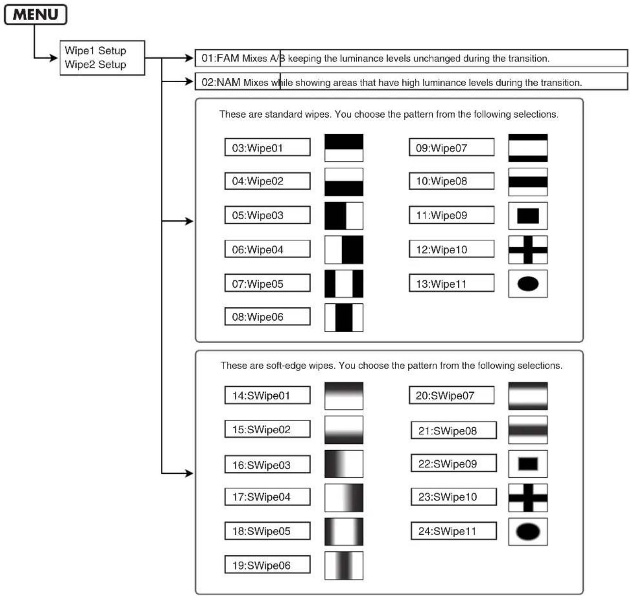
flowchart
graph TD
    A["MENU"] --> B["Wipe1 Setup\nWipe2 Setup"]
    B --> C["01:FAM Mixes A/B keeping the luminance levels unchanged during the transition."]
    B --> D["02:NAM Mixes while showing areas that have high luminance levels during the transition."]
    C --> E["These are standard wipes. You choose the pattern from the following selections."]
    D --> E
    E --> F["03:Wipe01"]
    E --> G["04:Wipe02"]
    E --> H["05:Wipe03"]
    E --> I["06:Wipe04"]
    E --> J["07:Wipe05"]
    E --> K["08:Wipe06"]
    G --> L["09:Wipe07"]
    G --> M["10:Wipe08"]
    G --> N["11:Wipe09"]
    G --> O["12:Wipe10"]
    G --> P["13:Wipe11"]
    H --> Q["These are soft-edge wipes. You choose the pattern from the following selections."]
    I --> Q
    J --> Q
    K --> Q
    L --> R["14:SWipe01"]
    L --> S["15:SWipe02"]
    L --> T["16:SWipe03"]
    L --> U["17:SWipe04"]
    L --> V["18:SWipe05"]
    L --> W["19:SWipe06"]
    M --> X["20:SWipe07"]
    M --> Y["21:SWipe08"]
    M --> Z["22:SWipe09"]
    M --> AA["23:SWipe10"]
    M --> AB["24:SWipe11"]
MEMO
When shipped from the factory, 05:Wipe03 is assigned to WIPE1 and 22:SWipe09 is assign to WIPE2 by default.
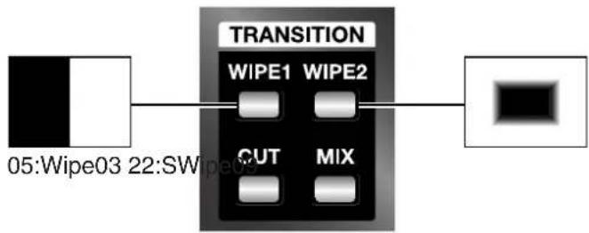
flowchart
graph LR
    A["05:Wipe03 22:SWIPE1"] --> B["TRANSITION"]
    B --> C["WIPE1 WIPE2"]
    B --> D["CUT MIX"]
    B --> E["Black Box"]
Menu List
PinP Setup Menu
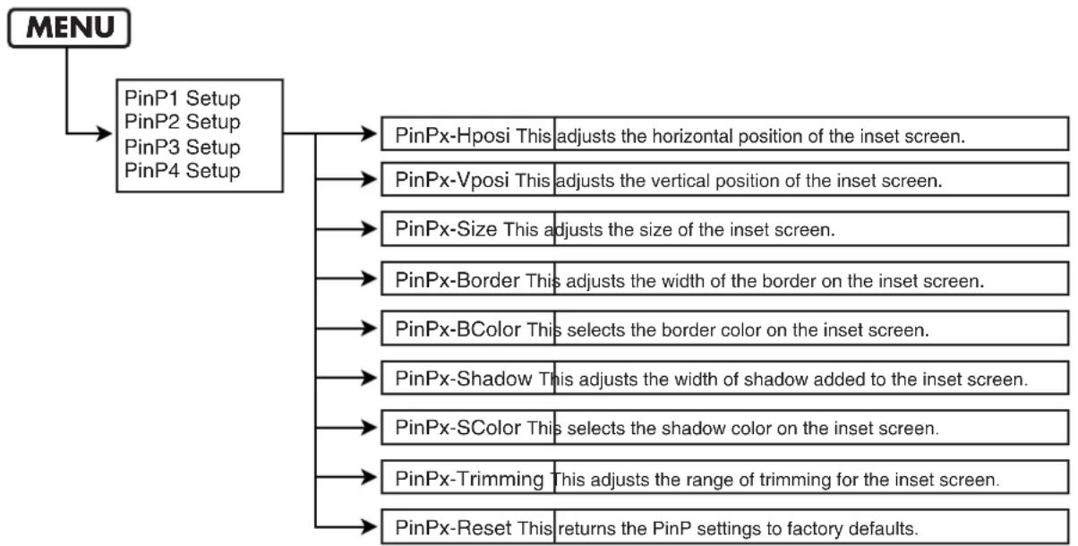
flowchart
graph TD
    A["MENU"] --> B["PinP1 Setup\nPinP2 Setup\nPinP3 Setup\nPinP4 Setup"]
    B --> C["PinPx-Hposi This adjusts the horizontal position of the inset screen."]
    B --> D["PinPx-Vposi This adjusts the vertical position of the inset screen."]
    B --> E["PinPx-Size This adjusts the size of the inset screen."]
    B --> F["PinPx-Border This adjusts the width of the border on the inset screen."]
    B --> G["PinPx-BColor This selects the border color on the inset screen."]
    B --> H["PinPx-Shadow This adjusts the width of shadow added to the inset screen."]
    B --> I["PinPx-SColor This selects the shadow color on the inset screen."]
    B --> J["PinPx-Trimming This adjusts the range of trimming for the inset screen."]
    B --> K["PinPx-Reset This returns the PinP settings to factory defaults."]
*In the "PinPx-Hposi" and other items described above, a number from 1 through 4 appears at the location shown by "x." For example, a "1" is inserted when "PinP1 Setup" has been selected, and a "4" is inserted when "PinP4 Setup" has been selected.
MEMO
In the factory-default state, the locations of the inset screen for PinP1 through PinP4 are as shown below. All selections from 1 through 4 have a white border added. By default, no shadow is added.
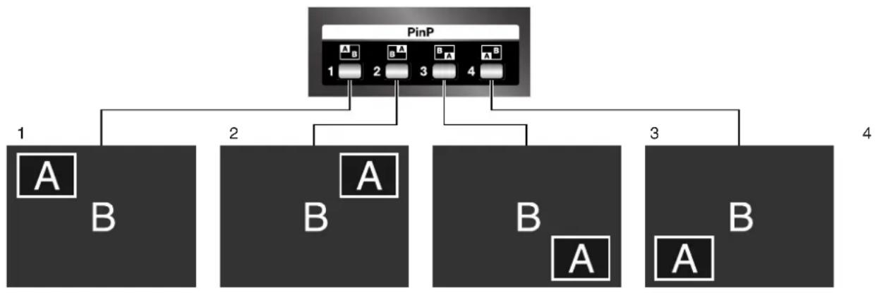
flowchart
graph TD
    PinP["PinP"] --> A1["A"]
    PinP --> A2["B"]
    PinP --> A3["A"]
    PinP --> A4["A"]
    PinP --> A5["B"]
    PinP --> A6["A"]
    PinP --> A7["B"]
    PinP --> A8["A"]
    PinP --> A9["B"]
PC Input Setup Menu
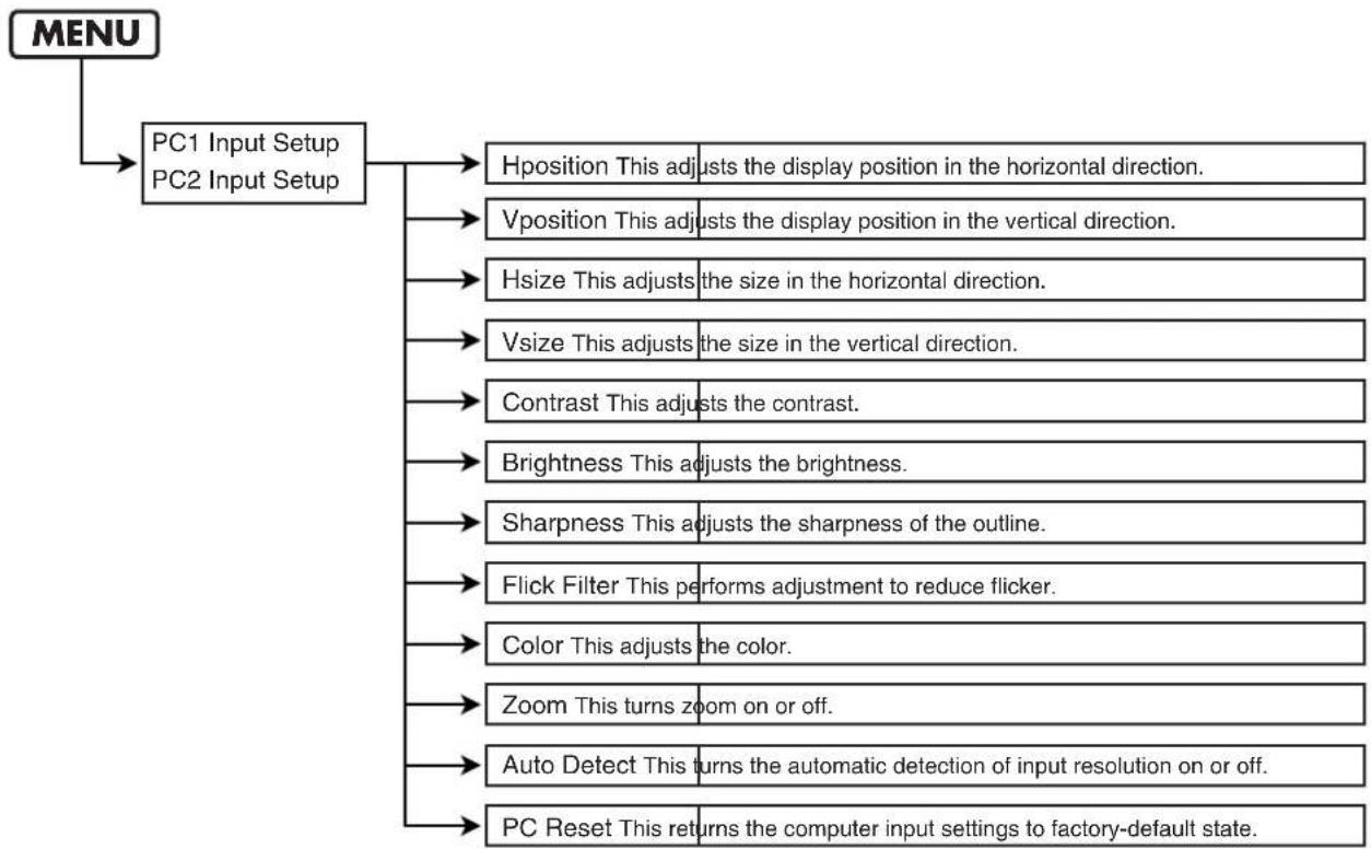
flowchart
graph TD
    A["MENU"] --> B["PC1 Input Setup PC2 Input Setup"]
    B --> C["Hposition This adjusts the display position in the horizontal direction."]
    B --> D["Vposition This adjusts the display position in the vertical direction."]
    B --> E["Hsize This adjusts the size in the horizontal direction."]
    B --> F["Vsize This adjusts the size in the vertical direction."]
    B --> G["Contrast This adjusts the contrast."]
    B --> H["Brightness This adjusts the brightness."]
    B --> I["Sharpness This adjusts the sharpness of the outline."]
    B --> J["Flick Filter This performs adjustment to reduce flicker."]
    B --> K["Color This adjusts the color."]
    B --> L["Zoom This turns zoom on or off."]
    B --> M["Auto Detect This turns the automatic detection of input resolution on or off."]
    B --> N["PC Reset This returns the computer input settings to factory-default state."]
DSK Setup Menu
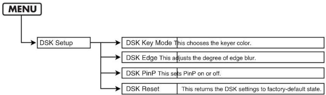
flowchart
graph TD
    A["MENU"] --> B["DSK Setup"]
    B --> C["DSK Key Mode This chooses the keyer color."]
    B --> D["DSK Edge This adjusts the degree of edge blur."]
    B --> E["DSK PinP This sets PinP on or off."]
    B --> F["DSK Reset This returns the DSK settings to factory-default state."]
MEMO
In the factory-default state, black is the key color for key composition. This produces attractive composition of white text or logos on a black background, as shown below. Edges are slightly blurred.

Menu List
Output Fade Menu
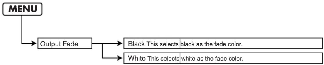
flowchart
graph TD
    A["MENU"] --> B["Output Fade"]
    B --> C["Black This selects black as the fade color."]
    B --> D["White This selects white as the fade color."]
MEMO
In the factory-default state, this is set to black.
Panel Preset Edit Menu
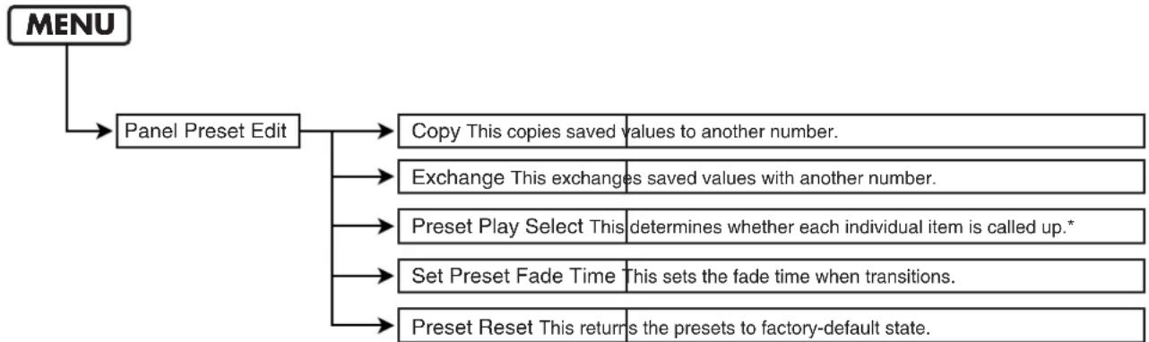
flowchart
graph TD
    A["MENU"] --> B["Panel Preset Edit"]
    B --> C1["Copy This copies saved values to another number."]
    B --> C2["Exchange This exchanges saved values with another number."]
    B --> C3["Preset Play Select This determines whether each individual item is called up.*"]
    B --> C4["Set Preset Fade Time This sets the fade time when transitions."]
    B --> C5["Preset Reset This returns the presets to factory-default state."]
*When a saved state is recalled by pressing a PANEL PRESET button, only items for which "Load" has been selected are called up. The saved state is not called up for items for which "Free" has been selected. When you want to keep the input channels for A Bus and B Bus unchanged while changing the values of all other items to a saved state, set the "A-BUS/B-BUS" item to "Free."
MEMO
In the factory-default state, all items are set to "Load." This means the saved state is called up for all items.
Panel Mode Setup Menu
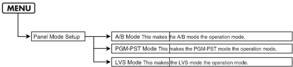
flowchart
graph TD
    A["MENU"] --> B["Panel Mode Setup"]
    B --> C["A/B Mode This makes the A/B mode the operation mode."]
    B --> D["PGM-PST Mode This makes the PGM-PST mode the operation mode."]
    B --> E["LVS Mode This makes the LVS mode the operation mode."]
MEMO
In the factory-default state, the A/B mode is set as the operation mode. For more information on how to operate the unit in other modes, refer to "Use in Other Operation Modes Besides the A/B Mode" (p. 19).
MIDI Setup Menu
These settings are required when operating the unit by remote control.
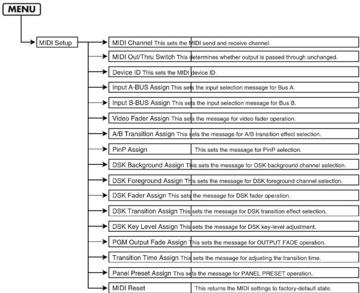
flowchart
graph TD
    A["MENU"] --> B["MIDI Setup"]
    B --> C1["MIDI Channel This sets the MIDI send and receive channel."]
    B --> C2["MIDI Out/Thru Switch This determines whether output is passed through unchanged."]
    B --> C3["Device ID This sets the MIDI device ID."]
    B --> C4["Input A-BUS Assign This sets the input selection message for Bus A."]
    B --> C5["Input B-BUS Assign This sets the input selection message for Bus B."]
    B --> C6["Video Fader Assign This sets the message for video fader operation."]
    B --> C7["A/B Transition Assign This sets the message for A/B transition effect selection."]
    B --> C8["PinP Assign This sets the message for PinP selection."]
    B --> C9["DSK Background Assign This sets the message for DSK background channel selection."]
    B --> C10["DSK Foreground Assign This sets the message for DSK foreground channel selection."]
    B --> C11["DSK Fader Assign This sets the message for DSK fader operation."]
    B --> C12["DSK Transition Assign This sets the message for DSK transition effect selection."]
    B --> C13["DSK Key Level Assign This sets the message for DSK key-level adjustment."]
    B --> C14["PGM Output Fade Assign This sets the message for OUTPUT FADE operation."]
    B --> C15["Transition Time Assign This sets the message for adjusting the transition time."]
    B --> C16["Panel Preset Assign This sets the message for PANEL PRESET operation."]
    B --> C17["MIDI Reset This returns the MIDI settings to factory-default state."]
Utility Menu
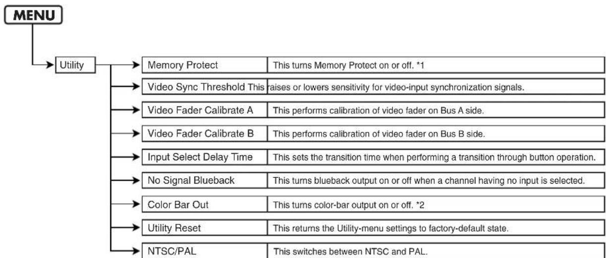
flowchart
graph TD
    A["MENU"] --> B["Utility"]
    B --> C["Memory Protect"]
    C --> D["This turns Memory Protect on or off. *1"]
    B --> E["Video Sync Threshold This"]
    E --> F["aises or lowers sensitivity for video-input synchronization signals."]
    B --> G["Video Fader Calibrate A"]
    G --> H["This performs calibration of video fader on Bus A side."]
    B --> I["Video Fader Calibrate B"]
    I --> J["This performs calibration of video fader on Bus B side."]
    B --> K["Input Select Delay Time"]
    K --> L["This sets the transition time when performing a transition through button operation."]
    B --> M["No Signal Blueback"]
    M --> N["This turns blueback output on or off when a channel having no input is selected."]
    B --> O["Color Bar Out"]
    O --> P["This turns color-bar output on or off. *2"]
    B --> Q["Utility Reset"]
    Q --> R["This returns the Utility-menu settings to factory-default state."]
    B --> S["NTSC/PAL"]
    S --> T["This switches between NTSC and PAL."]
*1 When Memory Protect is on, PANEL PRESET settings can be called up, but setting values cannot be changed or saved. It also becomes impossible to change the setting values for any menu items.
*2 The settings for other items persist in memory after the power is switched off, but the on/off setting for color-bar output is not saved.
Power Supply
The power does not come on when the POWER switch is turned on.
- Is an AC adapter other than the included one being connected? Use the included AC adapter (Roland PSB-7U).
Video Output
No picture is output.
- If the PGM OUTPUT FADE button illuminated? No video is output while the output fade button is lighted. "Applying Fade to the Final Output (PGM OUT)" (p. 30)
- Are the selections for the input channels correct? When selecting the input for A Bus or B Bus, selecting a channel that has no input signal results in no picture being output. "Switching Between A Bus and B Bus" (p. 16)
- Is any signal being output from the connected camera or playback device? Check the source monitor connected to a MONITOR OUT connector.
The picture is corrupt.
- Is the selection of NTSC or PAL correct? "Switching Between NTSC and PAL" (p. 35)
- The signal from the camera or other source device may be below the threshold value. Go to the "Utility" menu and try adjusting the "Video Sync Threshold" setting.
- A weak incoming video signal can cause PGM output to be black-and-white or distorted. Make sure your video source devices and cabling are providing adequate video signal.
- Is a moving image being input from a computer? Flicker or skew may occur in moving images input from a computer. This is called tearing, and does not indicate an equipment malfunction.
- Was the input channel for one bus changed while the video fader was at a position short of fully moved to the opposite end? When you're switching the input channel for the bus other than the one displayed, first move the video fader all the way to the end of its stroke. "Switching Between A Bus and B Bus" (p. 16)
Operating the video fader does not change the picture.
- Is the same input channel selected for A Bus and B Bus? If the same input channel has been selected, operating the video fader does not change the output picture. "Switching Between A Bus and B Bus" (p. 16)
- Is the operation mode set to the PGM-PST mode? In this mode, only button operations can be used to change the picture. Operating the video fader has no effect. "Use in Other Operation Modes Besides the A/B Mode" (p. 19)
- The video fader might not be calibrated correctly. To perform calibration, go to the "Utility" menu and execute "Video Fader Calibrate" (A and B). Move the control all the way to the A Bus end and execute "Video Fader Calibrate A," then move it all the way to the B Bus end and execute "Video Fader Calibrate B."
DSK
Logos or text from a computer are not displayed.
- Is the video output from the computer in a format that the LVS-800 does not support? Change the settings on the computer to enable output in a supported format.
"Connecting Computers" (p. 11)
- Is the input from the computer selected as the FOREGROUND picture? No key composition is applied to the BACKGROUND picture.
- Is KEY LEVEL for DSK set at MAX? Turning the dial all the way to MAX makes the picture set as FOREGROUND disappear from view. "Trying Out DSK Composition" (p. 27)
Composition with the background picture does not look correct.
- Has the color to use for key composition been set correctly? By default, black is used for composition. Inputting a background image of a color other than black results in incorrect compositing with the background picture. Go to the "DSK Setup" menu and use "DSK Key Mode" to change the color to use for key composition.
"Trying Out DSK Composition" (p. 27)
Others
Menu settings are not saved.
- Was the power turned off before you quit the menu display? The values of menu settings are saved in internal memory when you exit the menu. To save the values of settings after making any changes, first quit the menu display before you switch off the power.
Settings cannot be saved to a PANEL PRESET.
- Do the controls allow their states to be saved? For some controls, saving the current state is not possible.
- Was the button used as the destination for saving held depressed until all PANEL PRESET buttons started to flash? Holding down the button for several seconds makes the buttons flash and saves the settings in internal memory, but the values are not saved until the buttons flash. "Saving Settings to PANEL RESET Buttons" (p. 31)
- Is Memory Protect set at the "On" setting? Go to the "Utility" menu, choose "Memory Protect," and select "Off." The unit cannot be returned to its factory-default state.
- Is Memory Protect set at the "On" setting? Go to the "Utility" menu, choose "Memory Protect," and select "Off."
| Video Processing | Input Connectors | |||
| Format | NTSC/PAL (ITU601) | Video | S-Video (4 pins mini DIN type) x 4 (ch 5, 6, 7, 8)Composite (BNC type) x 6 (ch 1, 2, 3, 4, 5, 6)* If S-Video is simultaneously input to 5-8, S-Video takes priority. | |
| Sampling | 13.5 MHz, 4:2:2 (Y:R-Y:B-Y), 8 bit | |||
| Frame Synchronizer | Built in x 3 | RGB | D-Sub 15 pin shrink type x 2 (PC1, PC2)* If S-Video is simultaneously input to ch 7-8, S-Video takes priority. | |
| Supported RGB Inputs | 640 x 480/120 Hz, 800 x 600/120 Hz,832 x 624/75 Hz, 1024 x 768/80 Hz,1152 x 864/80 Hz, 1152 x 870/75 Hz,1280 x 1024/75 Hz, 1600 x 1200/60 Hz* Conforms to VESA DMTVer 1.0 Revision 10* The refresh rate is the maximum valueof each resolution. | RemoteControl | MIDI (IN, OUT/THRU),RS-232C (D-Sub 9 pin type) | |
| Output Connectors | ||||
| MONITOR Composite (BNC type) x 8 | ||||
| A/B MIX S-Video (4 pins mini DIN type) x 1,Composite (BNC type) x 2 | ||||
| A/B MIX PVW | Composite (BNC type) x 1* Preview and OSD Menu | |||
| Input Level and Impedance | ||||
| Video (Composite) | 1.0Vp-p, 75 ohms | PGM OUT S-Video (4 pins mini DIN type) x 1,Composite (BNC type) x 2 | ||
| S-Video | Luminance signal : 1.0 Vp-p, 75 ohmsChrominance Signal : 0.286 Vp-p, 75 ohms (NTSC)0.3 Vp-p, 75 ohms (PAL) | PGM OUT PVW | Composite (BNC type) x 1* Preview of ch 6-8 or A/B MIX OUT | |
| PC-RGB | 0.7 Vp-p, 75 ohms (H, V:5VTTL) | TALLY D-Sub | 15 pin shrink type x 1, Max Input : 12 V,200 mA Open collector type | |
| Output Level and Impedance | ||||
| 1.0 Vp-p, 75 ohmsVideo (Composite) | Others | |||
| S-Video | Luminance signal : 1.0 Vp-p, 75 ohmsChrominance Signal : 0.286 Vp-p, 75 ohms (NTSC)0.3 Vp-p, 75 ohms (PAL) | Power Supply | AC Adaptor : Roland PSB-7U | |
| Current Draw | 2,200 mA | |||
| Transition Effects | ||||
| A/B MIX | Cut, Mix,Hard Edge Wipe, Soft Edge Wipe | Dimensions | 376.0(W) x 315(D) x 136(H) mm14-13/16(W) x 12-7/16(D) x 5-3/8 (D) inches | |
| DSK | Cut, Mix | Weight | 4.3 kg9 lbs 8 oz | |
| Composition Effects | ||||
| A/B MIX | Picture In Picture | Accessories | AC Adaptor (Roland PSB-7U),RCA to BNC adaptor x 4,Owner's Manual | |
| DSK | Luminance Key, Chroma Key,Picture In Picture | |||
*In the interest of product improvement, the specifications and/or appearance of this unit are subject to change without prior notice.
Remote Control
For more information about remote control via MIDI, V-LINK, or the RS-232C interface, please download the separately available reference document from the following Roland website.
http://www.rolandsystemsgroup.net/
A
A/B MIX OUT 10
A/B MIX PVW 10
A/B Mode 16
AUTO Button 18
B
background 9,27
C
Cord Hook 14
D
Downstream Keyer 26
DSK 26,29
F
Factory Reset 34
Fade 30
Final Output ...... 30
foreground 9,27
G
ground terminal 14
K
KEY LEVEL 9
L
LVS Mode 21
LVS mode 19
M
Menu 36
Menu List 38
MIDI 8
MONITOR OUT 10
N
NTSC 35
0
Operation Mode 19
OUTPUT FADE 9
P
PAL 35
PANEL PRESET 8,31
PC INPUT 10
PGM OUT 10
PGM PVW 10
PGM-PST Mode 20
PGM-PST mode 19
Picture-in-Picture 22
PinP 8
R
RS-232C 10
S
SETUP 8
Source 11
T
TALLY 10, 13
T-bar 9
TIME Dial 8
transition 9
transition effect 16
transition time 18
V
video fader 9
VIDEO INPUT 10
V-LINK 8
Memo
Memo
Memo
For EU Countries


This symbol indicates that in EU countries, this product must be collected separately from household waste, as defined in each region. Products bearing this symbol must not be discarded together with household waste.

This equipment has been tested and found to comply with the limits for a Class B digital device, pursuant to Part 15 of the FCC Rules. These limits are designed to provide reasonable protection against harmful interference in a residential installation. This equipment generates, uses, and can radiate radio frequency energy and, if not installed and used in accordance with the instructions, may cause harmful interference to radio communications. However, there is no guarantee that interference will not occur in a particular installation. If this equipment does cause harmful interference to radio or television reception, which can be determined by turning the equipment off and on, the user is encouraged to try to correct the interference by one or more of the following measures:
— Reorient or relocate the receiving antenna.
— Increase the separation between the equipment and receiver.
- Connect the equipment into an outlet on a circuit different from that to which the receiver is connected.
- Consult the dealer or an experienced radio/TV technician for help.
This device complies with Part 15 of the FCC Rules. Operation is subject to the following two conditions:
(1) this device may not cause harmful interference, and
(2) this device must accept any interference received, including interference that may cause undesired operation.
Unauthorized changes or modification to this system can void the users authority to operate this equipment.
This equipment requires shielded interface cables in order to meet FCC class B Limit.
For Canada
NOTICE
This Class B digital apparatus meets all requirements of the Canadian Interference-Causing Equipment Regulations.
AVIS
This product contains chemicals known to cause cancer, birth defects and other reproductive harm, including lead.
For the USA
DECLARATION OF CONFORMITY Compliance Information Statement
Type of Equipment : Video Mixer
Responsible Party : Roland Systems Group U.S.
Address: 425 Sequoia Drive, Suite 114, Bellingham, WA 98226
Telephone : (360) 594-4282
Information
When you need repair service, call your nearest EDIROL/Roland Service Center or authorized EDIROL/Roland distributor in your country as shown below.
AFRICA
SOUTH AFRICA
Paul Bothner(PTY) Ltd.
Royal Cape Park, Unit 24
Londonderry Road, Ottery 7800
Cape Town, SOUTH AFRICA
TEL:(021)7994900
ASIA
INDONESIA
PT. Citra IntiRama
5F. No.1500 Pingliang Road
Shanghai 200090, CHINA
TEL:(021)5580-0800
Roland Shanghai Electronics Co., Ltd.
(BEIJING OFFICE)
10F. No.18 3 Section Anhuaxili
Chaoyang District Beijing
100011 CHINA
TEL: (010) 6426-5050
KOREA
KOREA AVICS CO., LTD.
Unit B-2208, Woolimblue9,
240-21, Yeomchang-dong,
Gangseo-gu, Seoul, Korea
Tel: 02-322-3264
TAIWAN
ROLAND TAIWAN
ENTERPRISE CO., LTD.
Room 5, 9fl. No. 112 Chung Shan
N.Road Sec.2, Taipei, TAIWAN, R.O.C.
TEL:(02) 2561 3339
SINGAPORE/
MALAYSIA
Roland Asia Pacific Sdn. Bhd.
45-1, Block C2, Jalan PJU 1/39,
Dataran Prima, 47301 Petaling Jaya,
Selangor, MALAYSIA
TEL: 3-7805-3263
CENTRAL/LATIN AMERICA
BRAZIL
Roland Brasil Ltda.
Rua San Jose, 211
Parque Industrial San Jose
Cotia - Sao Paulo - SP, BRAZIL
TEL: (011) 4615 5666
Other CENTRAL/ LATIN AMERICA
Roland Systems Group U.S.
425 Sequoia Drive Suite 114,
Bellingham, Washington,
98226 USA
TEL: 360-594-4282
EUROPE
AUSTRIA/GERMANY/
ITALY/IRELAND/
UNITED KINGDOM
EDIROL (Europe) Ltd.
Studio 3.4 114 Power Road London
W4 5PY
U.K.
TEL: (0)20 8747 5949
BELGIUM/FRANCE/
LUXEMBOURG/
SWITZERLAND/
HOLLAND/SPAIN/
PORTUGAL
Roland Iberia, S.L.
Paseo Garcia Faria, 33-35
08005 Barcelona SPAIN
TEL: 93 493 91 00
CROATIA
ART-CENTAR
Degenova 3.
HR - 10000 Zagreb
TEL: (1) 466 8493
CZECH REP.
CZECH REPUBLIC DISTRIBUTOR
s.r.o
Voctárova 247/16
CZ - 180 00 PRAHA B,
CZECH REP
TEL:(2)830 20270
DENMARK
Roland Scandinavia A/S
Nordhavnsvej 7, Postbox 880,
DK-2100 Copenhagen
DENMARK
TEL: 3916 6200
FINLAND
Roland Scandinavia As, Filial
Finland
Vanha Nurmijarventie 62
01670 Vantaa
Finland
TEL:(0)9 68 24 020
NORWAY
Roland Scandinavia Avd.
Kontor Norge
Danvik Center 28, 2 tr.
S-131 30 Nacka SWEDEN
TEL:(0)8 702 00 20
HUNGARY
Roland East Europe Ltd.
2045 Torokbalint, FSD Park, building 3.
TEL: (23) 511011
POLAND
ROLAND POLSKA SP. Z O.O.
No.41 Nike St., Dr.Shariyati Ave.,
Roberoye Cerahe Mirdamad
Tehran, IRAN
TEL:(021)-2285-4169
OCEANIA
AUSTRALIA/
NEW ZEALAND
Roland Corporation
Australia Pty., Ltd.
38 Campbell Avenue
Dee Why West, NSW 2099
AUSTRALIA
For Australia
Tel: (02) 9982 8266
For New Zealand
Tel: (09) 3098 715
NORTH AMERICA
CANADA
Roland Canada Ltd.
(Head Offi ce)
5480 Parkwood Way, Richmond B.
C., V6V 2M4 CANADA
TEL: (604) 270 6626
Roland Canada Ltd.
(Toronto Offi ce)
170 Admiral Boulevard
Mississauga ON L5T 2N6 CANADA
TEL: (905) 362 9707
U.S.A.
Roland Systems Group U.S.
425 Sequoia Drive Suite 114,
Bellingham, Washington,
98226 USA
- INSTRUCTIONS FOR THE PREVENTION OF FIRE, ELECTRIC SHOCK, OR INJURY TO PERSONS
- ALWAYS OBSERVE THE FOLLOWING
- WARNING
- CAUTION
- Power Supply
- Placement
- Maintenance
- Additional Precautions
- Check the included items
- Top Panel
- V-LINK Button
- What's V-LINK?
- MEMO
- SETUP Buttons (p. 36)
- TIME Dial
- PANEL PRESET Buttons (p. 31)
- PinP Buttons (p. 22)
- A Bus/PGM Input Selectors (p. 16)
- B Bus/PST Input Selectors (p. 16)
- TRANSITION Buttons for A/B MIX (p. 16)
- AUTO Button for A/B MIX (p. 18)
- TRANSITION Indicator
- Video Fader (p. 17)
- PGM OUTPUT FADE Button (p. 30)
- BACKGROUND Buttons (p. 27)
- FOREGROUND Buttons (p. 27)
- TRANSITION Buttons for DSK (p. 27)
- AUTO Button for DSK (p. 28)
- Rear Panel
- PGM PVW Connector
- PGM OUT Connectors
- A/B MIX PVW Connector
- A/B MIX OUT Connectors
- PC INPUT Connectors
- VIDEO INPUT (Composite) Connectors
- MONITOR OUT Connectors
- POWER Button
- AC Adapter Connector
- MIDI IN and OUT/THRU Connectors
- RS-232C Connector
- TALLY Connector
- VIDEO INPUT (S-Video) Connectors
- Connecting Source Devices
- Connecting Video Devices
- Connecting Computers
- NOTE
- Connecting Output Devices
- The Difference Between A/B MIX OUT and PGM OUT
- TALLY Output
- Connecting the AC adaptor
- About Cord Hook
- Caution regarding the power supply
- Unsuitable places for connection
- Turning the power on
- Turning the power off
- Switching Between A Bus and B Bus
- Switching the Picture in the A/B Mode
- Switching the Picture Using the Video Fader
- Choose the A Bus and B Bus video.
- Choose the type of transition (transition effect).
- Move the video fader.
- The LEDs of the Input Selector Buttons
- Switching Using the AUTO Button
- Choose the type of transition (transition effect).
- Set the transition time.
- Perform the transition.
- Use in Other Operation Modes Besides the A/B Mode
- Changing the Operation Mode
- From the menu, select "Panel Mode Setup."
- Choose "PGM-PST Mode" or "LVS Mode."
- End the menu display.
- The Names of the Buses in the PGM-PST Mode
- Switching After Monitoring the Preview Picture (PGM-PST Mode)
- Choose the video channel on the PST side.
- Switching the Picture Directly (LVS Mode)
- Using Picture-in-Picture to Composite Two Screens
- Composition in the A/B Mode or LVS Mode
- Choose the picture to display in the inset screen.
- Choose the picture to make the background.
- Press a [P in P] button.
- Move the video fader to the A Bus (inset screen) side.
- Move the video fader to the B Bus (background) side.
- TIP
- Composition in the PGM-PST Mode
- Choose the background channel.
- Display the background.
- Check the picture of the inset screen.
- Press a [P in P] button.
- Display the inset screen.
- Make the inset screen disappear.
- What's a Downstream Keyer (DSK)?
- Trying Out DSK Composition
- Choose the background picture.
- Choose the foreground picture.
- Decide how the keyed material appears and disappears.
- Using the Downstream Keyer (DSK)
- Perform composition and output.
- Adjust the key level.
- Combining DSK and Picture-in-Picture
- From the menu, select "DSK Setup" and "DSP PinP."
- Decide on the P in P number.
- Perform composition and output.
- Adjust the key level.
- Applying Fade to the Final Output
- Saving the Current Settings
- Put the unit in the state you want to save.
- Save the settings.
- Calling Up Saved Settings
- Copying Saved Settings to Another Button
- Display the menu.
- Select "Panel Preset Edit."
- Select "Copy."
- Select the numbers of the copy source and destination.
- Execute the copy operation.
- Exchanging Saved Settings with Another Button
- Select "Exchange."
- Select the numbers of the exchange source and destination.
- Execute the exchange operation.
- At the menu, choose "Factory Reset."
- Choose "Yes [ENTER] SW."
- Execute FACTORY RESET.
- Quit the menu screen.
- Switching Between NTSC and PAL
- Switching to NTSC at Startup
- Switching to PAL at Startup
- Changing Settings Using the Menus
- Displaying the Menus
- Menu Levels
- Menu Operations
- Choose the item whose setting you want to change.
- Decide on the setting-change item.
- Change the setting value.
- End the menu display.
- Menu List
- MIDI Setup Menu
- Utility Menu
- Video Output
- No picture is output.
- The picture is corrupt.
- Operating the video fader does not change the picture.
- DSK
- Logos or text from a computer are not displayed.
- Composition with the background picture does not look correct.
- Others
- Menu settings are not saved.
- Settings cannot be saved to a PANEL PRESET.
- Remote Control
- A
- B
- C
- D
- F
- G
- K
- L
- M
- N
- 0
- P
- R
- S
- T
- V
- For EU Countries
- NOTICE
- AVIS
- DECLARATION OF CONFORMITY Compliance Information Statement
- Information
- AFRICA
- SOUTH AFRICA
- ASIA
- INDONESIA
- KOREA
- 240-21, Yeomchang-dong,
- TAIWAN
- SINGAPORE/
- MALAYSIA
- CENTRAL/LATIN AMERICA
- BRAZIL
- Other CENTRAL/ LATIN AMERICA
- EUROPE
- AUSTRIA/GERMANY/
- ITALY/IRELAND/
- UNITED KINGDOM
- BELGIUM/FRANCE/
- LUXEMBOURG/
- SWITZERLAND/
- HOLLAND/SPAIN/
- PORTUGAL
- CROATIA
- CZECH REP.
- DENMARK
- FINLAND
- NORWAY
- HUNGARY
- POLAND
- OCEANIA
- AUSTRALIA/
- NEW ZEALAND
- NORTH AMERICA
- CANADA
- U.S.A.
Brand : ROLAND
Model : LVS-800
Category : Blender