
VR-5 - Blender ROLAND - Free user manual and instructions
Find the device manual for free VR-5 ROLAND in PDF.


| Product Type | Video Mixer / Switcher |
| Model | VR-5 |
| Brand | Roland |
| Number of Inputs | 4 (composite, S-Video, component) |
| Outputs | 2 (program, preview) |
| Video Format Support | NTSC, PAL |
| Effects | Built-in transitions, chroma key, picture-in-picture |
| Audio Support | Embedded audio via SDI (optional) |
| Control Interface | Front panel buttons and T-bar |
| Dimensions (W x D x H) | 210 x 250 x 44 mm |
| Weight | 1.2 kg |
| Power Supply | DC 12V, 1.5A (included adapter) |
| Power Consumption | 18 W |
| Input Connectors | 4 x BNC (composite), 4 x mini-DIN (S-Video) |
| Output Connectors | 2 x BNC (composite), 1 x D-sub (component) |
| PC Connection | USB 2.0 for firmware updates and control |
| Supported Resolutions | 720x480 (NTSC), 720x576 (PAL) |
| Cooling Method | Passive (fanless) |
| Operating Temperature | 0°C to 40°C |
| Storage Temperature | -20°C to 60°C |
| Accessories Included | AC adapter, USB cable, rack mount ears |
| Cleaning | Use a soft, dry cloth; avoid liquids |
| Safety Compliance | CE, FCC |
| Repairability | Refer to service manual; use only Roland parts |
Frequently Asked Questions - VR-5 ROLAND
User questions about VR-5 ROLAND
0 question about this device. Answer the ones you know or ask your own.
Ask a new question about this device
Download the instructions for your Blender in PDF format for free! Find your manual VR-5 - ROLAND and take your electronic device back in hand. On this page are published all the documents necessary for the use of your device. VR-5 by ROLAND.
USER MANUAL VR-5 ROLAND
Before using this unit, carefully read the sections entitled: "USING THE UNIT SAFELY"(p. 4) and "IMPORTANT NOTES" (p. 6). These sections provide important information concerning the proper operation of the unit. Additionally, in order to feel assured that you have gained a good grasp of every feature provided by your new unit, owner's manual should be read in its entirety. The manual should be saved and kept on hand as a convenient reference.
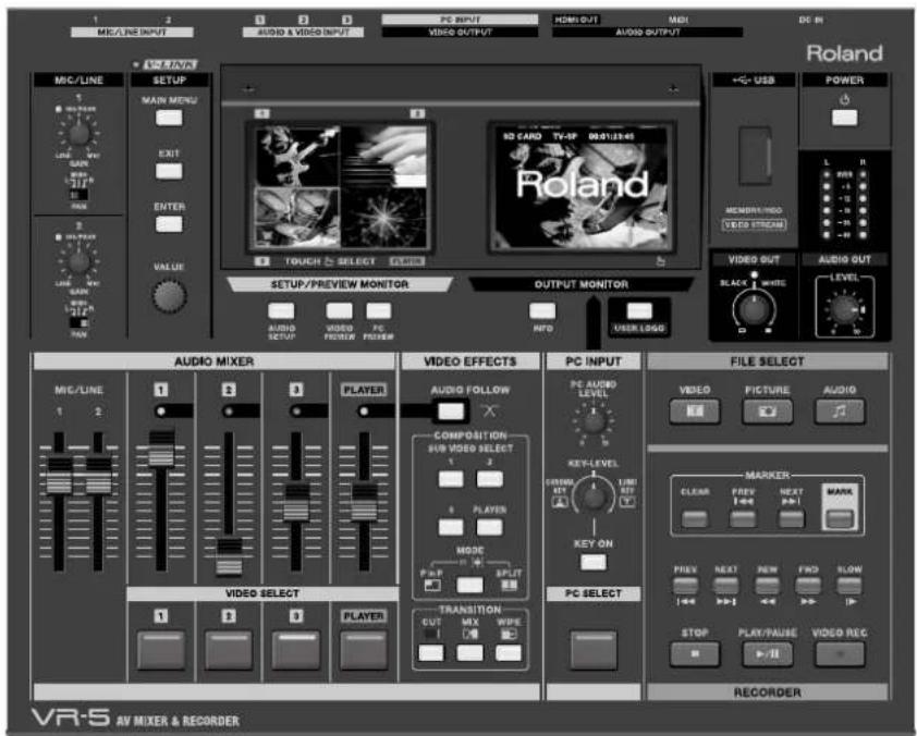
Copyright © 2010 ROLAND CORPORATION
All rights reserved. No part of this publication may be reproduced in any form without the written permission of ROLAND CORPORATION.
* Roland is either registered trademark or trademark of Roland Corporation in the United States and/or other countries.
* All product names mentioned in this document are trademarks or registered trademarks of their respective owners.
* The SD logo ( ) and CDHC logo ( ) are trademarks of SD-3C, LLC.
For the U.K.
IMPORTANT: THE WIRES IN THIS MAINS LEAD ARE COLOURED IN ACCORDANCE WITH THE FOLLOWING CODE.
BLUE: NEUTRAL
BROWN: LIVE
As the colours of the wires in the mains lead of this apparatus may not correspond with the coloured markings identifying the terminals in your plug, proceed as follows:
The wire which is coloured BLUE must be connected to the terminal which is marked with the letter N or coloured BLACK.
The wire which is coloured BROWN must be connected to the terminal which is marked with the letter L or coloured RED.
Under no circumstances must either of the above wires be connected to the earth terminal of a three pin plug.
The following items are included. Please make sure that all items are present. If anything is missing, please contact your dealer.
VR-5 itself
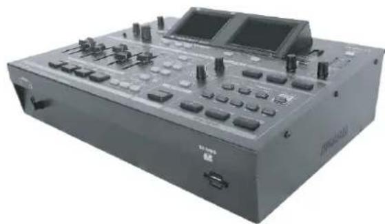
natural_image
Exterior view of a black audio workstation instrument with control knobs and a display (no visible text or labels)AC adaptor and power cord
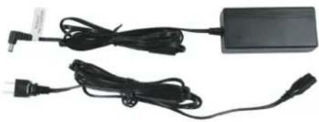
natural_image
Two black cables and a rectangular electronic device with connectors, no visible text or symbols.SD card (incl. movie/picture/audio contents)
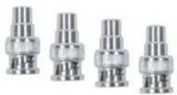
RCA - BNC conversion plug (four)
USB cable (A type - A type)
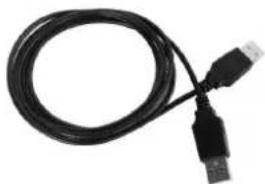
natural_image
Coiled black USB cable with two connectors (no text or symbols visible)Owner's manual (this document)
The explanations in this manual include illustrations that depict what should typically be shown by the display. Note, however, that your unit may incorporate a newer, enhanced version of the system, so what you actually see in the display may not always match what appears in the manual.
This product is using open source license (GPL/LGPL) software. You have the right to acquire, modify and distribute the source code for this open source license software. You can obtain the open source license source code used in this product by downloading it from the following website.
http://www.roland.com/support/gpl/
MMP (Moore Microprocessor Portfolio) refers to a patent portfolio concerned with microprocessor architecture, which was developed by Technology Properties Limited (TPL). Roland has licensed this technology from the TPL Group.
INSTRUCTIONS FOR THE PREVENTION OF FIRE, ELECTRIC SHOCK, OR INJURY TO PERSONS
About ⚠️ WARNING and ⚠️ CAUTION Notices
| WARNING | Used for instructions intended to alert the user to the risk of death or severe injury should the unit be used improperly. |
| CAUTION | Used for instructions intended to alert the user to the risk of injury or material damage should the unit be used improperly.* Material damage refers to damage or other adverse effects caused with respect to the home and all its furnishings, as well to domestic animals or pets. |
About the Symbols
| The △ symbol alerts the user to important instructions or warnings. The specific meaning of the symbol is determined by the design contained within the triangle. In the case of the symbol at left, it is used for | |
| The ⊗ symbol alerts the user to items that must never be carried out (are forbidden). The specific thing that must not be done is indicated by the design contained within the circle. In the case of the symbol at left, it means that the unit must never be disassembled. | |
| The ● symbol alerts the user to things that must be carried out. The specific thing that must be done is indicated by the design contained within the circle. In the case of the symbol at left, it means that the power-cord plug must be unplugged from the outlet. |
ALWAYS OBSERVE THE FOLLOWING
WARNING
- Do not open (or modify in any way) the unit or its AC adaptor.

- Do not attempt to repair the unit, or replace parts within it (except when this manual provides specific instructions directing you to do so). Refer all servicing to your retailer, the nearest Roland Service Center, or an authorized Roland distributor, as listed on the "Information" sheet.

- Never install the unit in any of the following locations. - Subject to temperature extremes (e.g., direct sunlight in an enclosed vehicle, near a heating duct, on top of heat-generating equipment); or are


• Damp (e.g., baths, washrooms, on wet floors); or are
- Exposed to steam or smoke; or are
- Subject to salt exposure; or are
- Humid; or are
- Exposed to rain; or are
• Dusty or sandy; or are
- Subject to high levels of vibration and shakiness.
- Make sure you always have the unit placed so it is level and sure to remain stable. Never place it on stands that could wobble, or on inclined surfaces.

- Be sure to use only the AC adaptor supplied with the unit. Also, make sure the line voltage at the installation matches the input voltage specified on the AC adaptor's body. Other AC adaptors may use a different polarity, or be designed for a different voltage, so their use could result in damage, malfunction, or electric shock.

- Use only the attached power-supply cord. Also, the supplied power cord must not be used with any other device

WARNING
- Do not excessively twist or bend the power cord, nor place heavy objects on it. Doing so can damage the cord, producing severed elements and short circuits. Damaged cords are fire and shock hazards!

- This unit, either alone or in combination with an amplifier and headphones or speakers, may be capable of producing sound levels that could cause permanent hearing loss. Do not operate for a long period of time at a high volume level, or at a level that is uncomfortable. If you experience any hearing loss or ringing in the ears, you should immediately stop using the unit, and consult an audiologist.

- Do not place containers containing liquid (e.g., flower vases) on this product. Never allow foreign objects (e.g., flammable objects, coins, wires) or liquids (e.g., water or juice) to enter into this product. Doing so may cause short circuits, faulty operation, or other malfunctions.


- Immediately turn the power off, remove the AC adaptor from the outlet, and request servicing by your retailer, the nearest Roland Service Center, or an authorized Roland distributor, as listed on the "Information" sheet when:

- The AC adaptor, the power-supply cord, or the plug has been damaged; or
- If smoke or unusual odor occurs
- Objects have fallen into, or liquid has been spilled onto the unit; or
- The unit has been exposed to rain (or otherwise has become wet); or
- The unit does not appear to operate normally or exhibits a marked change in performance.
• In households with small children, an adult should provide supervision until the child is capable of following all the rules essential for the safe operation of the unit.

WARNING
- Protect the unit from strong impact. (Do not drop it!)
- Do not force the unit's power-supply cord to share an outlet with an unreasonable number of other devices. Be especially careful when using extension cords—the total power used by all devices you have connected to the extension cord's outlet must never exceed the power rating (watts/amperes) for the extension cord. Excessive loads can cause the insulation on the cord to heat up and eventually melt through.


- Before using the unit in a foreign country, consult with your retailer, the nearest Roland Service Center, or an authorized Roland distributor, as listed on the "Information" sheet.

- Since Manganese Lithium Battery is built-in, never expose this unit to excessive heat such as sunshine, fire or the like.

CAUTION
- The unit and the AC adaptor should be located so their location or position does not interfere with their proper ventilation.

• Always grasp only the plug on the AC adaptor cord when plugging into, or unplugging from, an outlet or this unit.

- At regular intervals, you should unplug the AC adaptor and clean it by using a dry cloth to wipe all dust and other accumulations away from its prongs. Also, disconnect the power plug from the power outlet whenever the unit is to remain unused for an extended period of time. Any accumulation of dust between the power plug and the power outlet can result in poor insulation and lead to fire.

- Try to prevent cords and cables from becoming entangled. Also, all cords and cables should be placed so they are out of the reach of children.

- Never climb on top of, nor place heavy objects on the unit.

- Never handle the AC adaptor or its plugs with wet hands when plugging into, or unplugging from, an outlet or this unit.

- Before moving the unit, disconnect the AC adaptor and all cords coming from external devices.

- Before cleaning the unit, turn off the power and unplug the AC adaptor from the outlet (p. **).

- Whenever you suspect the possibility of lightning in your area, disconnect the AC adaptor from the outlet.

- Keep screws of earth terminal, accessory SD card or RCA - BNC conversion plug you may remove and included ferrite cores or rubber feet in a safe place out of children's reach, so there is no chance of them being swallowed accidentally.

- Always turn the phantom power off when connecting any device other than condenser microphones that require phantom power. You risk causing damage if you mistakenly supply phantom power to dynamic microphones, audio playback devices, or other devices that don't require such power. Be sure to check the specifications of any microphone you intend to use by referring to the manual that came with it.\n\n (This unit's phantom power: +48 V DC, 14 mA Max)

Power Supply
- Do not connect this unit to same electrical outlet that is being used by an electrical appliance that is controlled by an inverter (such as a refrigerator, washing machine, microwave oven, or air conditioner), or that contains a motor. Depending on the way in which the electrical appliance is used, power supply noise may cause this unit to malfunction or may produce audible noise. If it is not practical to use a separate electrical outlet, connect a power supply noise filter between this unit and the electrical outlet.
- The AC adaptor will begin to generate heat after long hours of consecutive use. This is normal, and is not a cause for concern.
- Before connecting this unit to other devices, turn off the power to all units. This will help prevent malfunctions and/or damage to monitors or other devices.
Placement
- Using the unit near power amplifiers (or other equipment containing large power transformers) may induce hum. To alleviate the problem, change the orientation of this unit; or move it farther away from the source of interference.
- This device may interfere with radio and television reception. Do not use this device in the vicinity of such receivers.
- Noise may be produced if wireless communications devices, such as cell phones, are operated in the vicinity of this unit. Such noise could occur when receiving or initiating a call, or while conversing. Should you experience such problems, you should relocate such wireless devices so they are at a greater distance from this unit, or switch them off.
- When moved from one location to another where the temperature and/or humidity is very different, water droplets (condensation) may form inside the unit. Damage or malfunction may result if you attempt to use the unit in this condition. Therefore, before using the unit, you must allow it to stand for several hours, until the condensation has completely evaporated.
- Depending on the material and temperature of the surface on which you place the unit, its rubber feet may discolor or mar the surface. You can place a piece of felt or cloth under the rubber feet to prevent this from happening. If you do so, please make sure that the unit will not slip or move accidentally.
Maintenance
- For everyday cleaning wipe the unit with a soft, dry cloth or one that has been slightly dampened with water. To remove stubborn dirt, use a cloth impregnated with a mild, non-abrasive detergent. Afterwards, be sure to wipe the unit thoroughly with a soft, dry cloth.
- Never use benzine, thinners, alcohol or solvents of any kind, to avoid the possibility of discoloration and/or deformation.
Additional Precautions
- This unit allows you to switch images sat high speed. For some people, viewing such images can cause headache, nausea, or other discomfort. Do not use this unit to create video that might cause these types of health problems. Roland Corporation will accept no responsibility for any such health problems that may occur in yourself or in viewers.
- Unfortunately, it may be impossible to restore the contents of data that was stored on SD cards once it has been lost. Roland Corporation assumes no liability concerning such loss of data.
- Use a reasonable amount of care when using the unit's buttons, sliders, or other controls; and when using its jacks and connectors. Rough handling can lead to malfunctions.
- Never strike or apply strong pressure to the display.
- When connecting / disconnecting all cables, grasp the connector itself—never pull on the cable. This way you will avoid causing shorts, or damage to the cable's internal elements.
- To avoid disturbing your neighbors, try to keep the unit's volume at reasonable levels. You may prefer to use headphones, so you do not need to be concerned about those around you (especially when it is late at night).
- When you need to transport the unit, package it in the box (including padding) that it came in, if possible. Otherwise, you will need to use equivalent packaging materials.
- Some connection cables contain resistors. Do not use cables that incorporate resistors for connecting to this unit. The use of such cables can cause the sound level to be extremely low, or impossible to hear. For information on cable specifications, contact the manufacturer of the cable.
Before Using SD Cards
- Carefully insert the SD card all the way in---until it is firmly in place.
- Never touch the terminals of the SD card. Also, avoid getting the terminals dirty.
- SD cards are constructed using precision components; handle the cards carefully, paying particular note to the following.
• To prevent damage to the cards from static electricity, be sure to discharge any static electricity from your own body before handling the cards.
- Do not touch or allow metal to come into contact with the contact portion of the cards.
- Do not bend, drop, or subject cards to strong shock or vibration.
- Do not keep cards in direct sunlight, in closed vehicles, or other such locations (storage temperature: -25 to +85 degrees C).
- Do not allow cards to become wet.
- Do not disassemble or modify the cards.
Copyright
- Recording, duplication, distribution, sale, lease, performance, or broadcast of copyrighted material (musical works, visual works, broadcasts, live performances, etc.) belonging to a third party in part or in whole without the permission of the copyright owner is forbidden by law.
- Do not use this unit for purposes that could infringe on a copyright held by a third party. We assume no responsibility whatsoever with regard to any infringements of third-party copyrights arising through your use of this unit.
About Intellectual Property Rights
- Recording, duplication, distribution, sale, lease, performance, or broadcast of copyrighted material (musical works, visual works, broadcasts, liver performances, etc.) belonging to a third party in part or in whole without the permissions of copyright owner is forbidden by law.
- Do not use this product for purposes that could infringe on a copyright held by a third party. We assume no responsibility whatsoever with regard to any infringements of third-party copyrights arising through your use of this product.
- The copyright of contents in accessory SD card (movie data, picture data and sound waveform data) of this product is reserved by Roland Corporation. Purchasers of this product are permitted to utilize said content for the creating, performing, recording and distributing original visual or musical works.
- Purchasers of this product are NOT permitted to extract said content in original or modified form, for the purposes of distributing recorded medium of said content or making them available on a computer network.
Others
• Security Slot http://www.kensington.com/
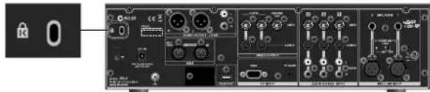
- This product is a Class A digital device for use in other than residential environment. Use of this equipment in a residential environment may cause radio interference requiring the user to take appropriate preventative measures. In such instances, take steps such as using cables with ferrite cores near their connectors. For information on specific preventive methods, contact your dealer, the nearest Roland Service Center, or an authorized Roland distributor, as listed on the "Information" sheet.
- When this device is connected to a video cameras or other such Class B equipment, the system as a whole is then classified as a Class A device.
Turning the Power On/Off.... 10
Connecting the AC adaptor....10
Turning the power on....11
Turning the power off....11
Names of Things and What They Do 12
Top Panel....12
Setup/Display Section ....13
Output Section....15
Audio Mixer Section 16
Video Select Section....17
Video Effects Section....17
PC INPUT Section....18
Recorder Section....19
File Select Section 19
Rear Panel....20
Front Panel....21
Signal Flow....22
Connecting External Equipment 23
Connecting Source Equipment....24
Connecting Video Equipment 24
Connect a computer. 24
Connecting Audio Equipment....25
Connecting Output Equipment 26
Basic Operation.... 28
Switching the Video 28
Adjusting the Volume Balance 30
Linking Audio to a Video Switching 31
Applying Effects to Audio....31
Applying a Fade to Final Video Output....33
Adjusting the Volume of the Final Output....33
Compositing the Video 34
Two-screen Composition Using Picture-in-Picture....34
Adjusting the Position of the Inset Screen....35
Two-screen Composition Using Split....36
Compositing a Logo or Text from a Computer 38
Performing Playback from an SD Card 40
Inserting an SD Card into the Slot 40
File Playback....42
Useful Playback Features....45
Playback Using Markers....45
SLOW Playback....46
Recording to an SD card.... 47
Formatting the SD card....48
Selecting a Recording Folder and Recording Mode....49
Record the Final Output ....50
Performing Output from the USB Port....51
Connect a computer....51
Performing Output to a Computer 52
Registering a User Logo 53
Other Features 54
Using the Features on the FILE UTILITY Menu....54
Returning to the Factory-default State 58
Changing Between NTSC and PAL....58
Adjusting the Internal Calendar/Clock....59
Menu Operations and Menu List 60
Menu Operations....60
Menu List....61
Appendices....65
Main Specifications....65
Remote Control....66
Error Messages 66
Troubleshooting....67
Artist Profiles 68
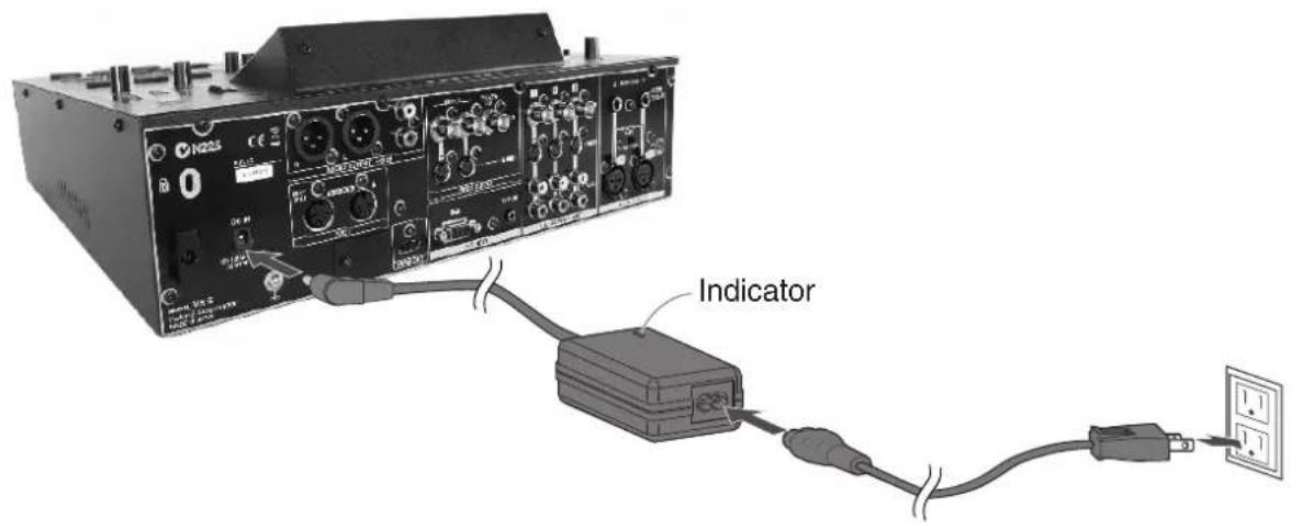
Connecting the AC adaptor
Connect the AC adaptor to VR-5. Place the AC adaptor so the side with the indicator (see illustration) faces upwards and the side with textual information faces downwards.
* The indicator will light when you plug the AC adaptor into an AC outlet.
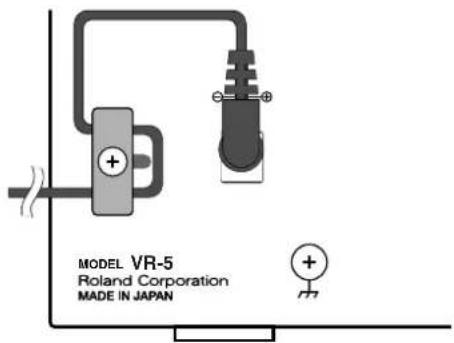
About Cord Hook
To prevent the inadvertent disruption of power to your unit (should the plug be pulled out accidentally), and to avoid applying undue stress to the AC adaptor jack, anchor the power cord using the cord hook, as shown in the illustration.
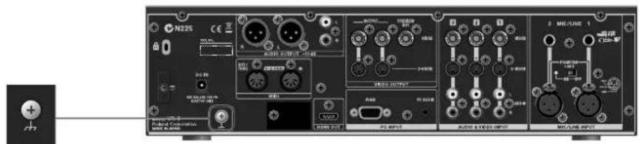
Caution regarding the power supply
Depending on the circumstances of a particular setup, you may experience a discomforting sensation, or perceive that the surface feels gritty to the touch when you touch this device, microphones connected to it, or the metal portions of other objects, such as video cameras. This is due to an infinitesimal electrical charge, which is absolutely harmless. However, if you are concerned about this, connect the ground terminal (see figure) with an external ground. When the unit is grounded, a slight hum may occur, depending on the particulars of your installation. If you are unsure of the connection method, contact the nearest Roland Service Center, or an authorized Roland distributor, as listed on the "Information" sheet.
Unsuitable places for connection
• Water pipes (may result in shock or electrocution)
• Gas pipes (may result in fire or explosion)
- Telephone-line ground or lightning rod (may be dangerous in the event of lightning)
Turning the power on
* Once the connections have been completed (p. 10), turn on power to your various devices in the order specified. By turning on devices in the wrong order, you risk causing malfunction and/or damage to speakers and other devices.
* Always make sure to have the volume level turned down before switching on power. Even with the volume all the way down, you may still hear some sound when the power is switched on, but this is normal, and does not indicate a malfunction.
* This unit is equipped with a protection circuit. A brief interval after power up is required before the unit will operate normally.
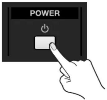
Make sure the power cable is securely inserted, then press the [POWER] button located on the top panel. The button lights up and the VR-5 starts.
Turning the power off
Press the [POWER] button on the top panel. At the screen on the right (OUTPUT MONITOR), the message "Press POWER Again!" appears.
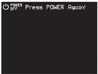
Pressing the [POWER] button again within 5 seconds after this message appears makes the button go dark and switches off the power to the VR-5.
NOTE
The "Press POWER Again!" message automatically disappears after 5 seconds. The power cannot be turned off unless the [POWER] button is pressed within 5 seconds after the message appears.
Top Panel
![1 MIC/LINE INPUT AUDIO & VIDEO INPUT AUDIO HDMI OUT HDMI VIDEO OUTPUT AUDIO OUTPUT 2 MIC/LINE MAIN MENU EXIT ENTER VALUE TITLE SETUP/PREVIEW MONITOR OUTPUT MONITOR AUDIO VIDEO PC 1 SD CARD TV-SP 00:01:23:49 Roland +L-USB POWER L N R MENORI/INDS [VIDEO STREAM] VIDEO OUT BLACK WORLD AUDIO OUT LEVEL AUDIO MIXER MIC/LINE 1 2 3 PLAYER VIDEO EFFECTS AUDIO FOLLOW COMPOSITION- BIR VIDEO SELECT 1 2 3 PLAYER MODE PLOT SPLIT KEY-LEVEL KEY ON PC INPUT PC AUDIO LEVEL VIDEO PICTURE AUDIO FILE SELECT VRS AV MIXER & RECORDER 3 4 6 7 5 8 MARKER- CLEAR PREV NEXT MARK PREV NEXT RAW FWD TLOW STOP PLAY/FAUSE VIDEO REC RECO IDER](/content/2026/05/901158/images/6b64620eee80960abd06f19e582efc9fb918bf441c399a2dd35928ad8c3ebe8f.jpg)
This page provides a general overview of the functioning of the various sections. For more information about each section, refer to the following pages.
1. Setup/Display Section (p. 13)
You can make the various system settings for the VR-5 by operating the SETUP buttons and dials.
The display area displays the input from source devices, and also displays the output.
The two monitors are touch panels, and you can switch the video and move inset-screen position for Picture-in-Picture by touching the screens.
2. Output Section (p. 15)
This section is for applying fade-in or fade-out to video output and making the final level adjustment for audio output. The POWER button for switching the unit's power on and off and a USB port for connecting a computer or other hardware are also located here.
3. Audio Mixer Section (p. 16)
This section is for adjusting the balance and mixing the audio inputs from the sources.
4. Video Select Section (p. 17)
This section is for switching the video inputs from the sources. When you are not using the touch panel on the left monitor to switch the video, use the buttons in this section to carry out the switching operations.
5. Video Effects Section (p. 17)
This section is for applying compositing and transition effects to video. When you wish to link audio fades to video transitions, use the [AUDIO FOLLOW] button in this section.
6. PC INPUT Section (p. 18)
This section is to overlay a logo or text from a computer onto video, and for adjusting level of audio input from a computer.
7. Recorder Section (p. 19)
This section is for controlling playback from an SD card and recording onto an SD card.
8. File Select Section (p. 19)
This section is for selecting the type of file to play back from an SD card.
Setup/Display Section
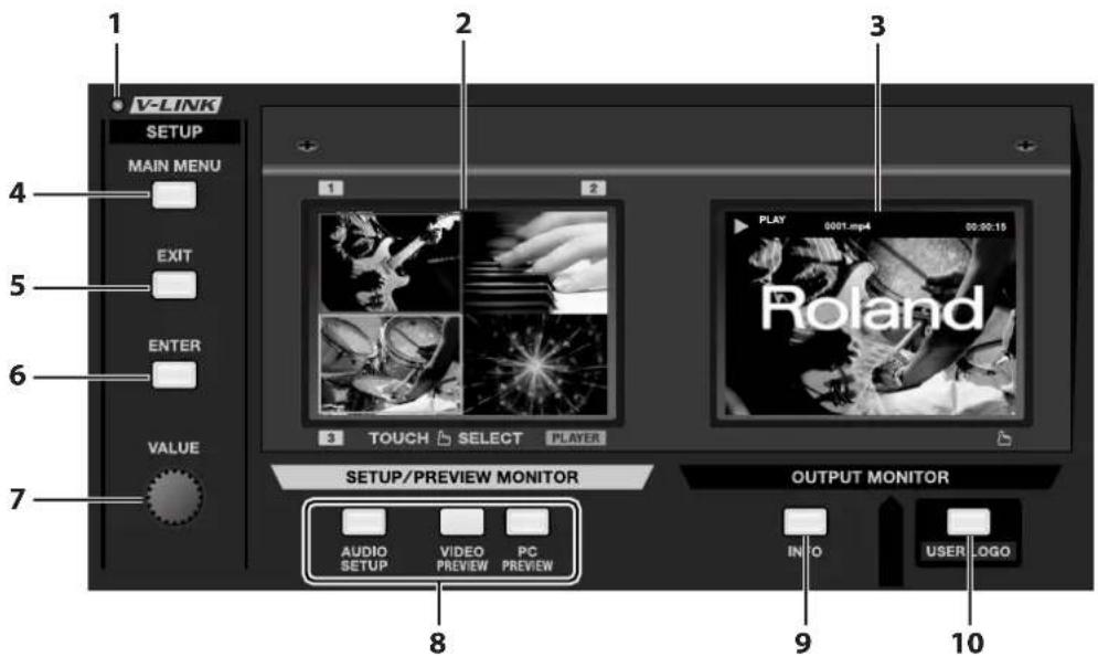
1. V-LINK Indicator
This lights up when a V-LINK-compatible external device is connected, and when V-LINK on the connected device is switched on. Refer to "Remote Control" (p. 66).
MEMO
V-LINK is a feature for performing video synchronized to music using MIDI. The V-LINK feature provides a quick and simple way to establish a link with musical instrument, music-production device, or video presenter of Roland.
2. SETUP/PREVIEW MONITOR
This displays input from source devices, as well as on-screen menus. As it is a touch panel, you can switch video by touching the screen.
3. OUTPUT MONITOR
This displays the results of video mixing carried out on the VR-5. The picture displayed here is output from the VIDEO OUTPUT connectors.
4. MAIN MENU Button (p. 60)
This calls up various setup menus for the VR-5. The menus are displayed on the SETUP/PREVIEW MONITOR.
NOTE
During display of a menu, no video input is shown on the SETUP/PREVIEW MONITOR. Use an external monitor connected to the PREVIEW OUT connector to view the video inputs.
5. EXIT Button
Use this button to quit menu screens or return to previous level.
6. ENTER Button
Use this button to apply setting values or enter into the next level.
7. VALUE Dial
This dial is for changing setting values.
* You can change a setting value up or down by 10 units while you are pressing down the dial and turn it.
8. View Mode Buttons
These select the following three view modes of the SETUP/PREVIEW MONITOR.
• AUDIO SETUP
This calls up the setting screen for the audio mixer.
• VIDEO PREVIEW
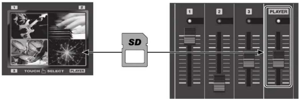
This displays the inputs from four sources using a four split screen. Here, [1] through [3] display the inputs from cameras or other external-source devices connected to the VIDEO INPUT connectors. [PLAYER] displays video played back from an SD card. When this mode is enabled, you can use the touch panel to switch video.
• PC PREVIEW
This displays the image from a computer connected to the PC INPUT connectors.
9. INFO Button
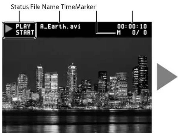
Pressing this makes it light up and displays the following information on the OUTPUT MONITOR. Pressing it a second time makes it go dark, and the displayed information disappears.
The information to be displayed when [INFO] is pressed has been changed as below from the shipped version.
- Current Status This displays current status like playback (PLAY) or recording (REC).
- File Name During playback, this displays the name of the currently selected file.
During recording, this displays the file name to be assigned to the recording file (the date/time when recording is started).
- Markers This displays the total number of added markers and the number of marker immediately before the current location. When no marker has been added, "0/0" is displayed.
- PLAY/REC time This displays the playback or recording time of the file in hour:minute:second (H:M:S) format.
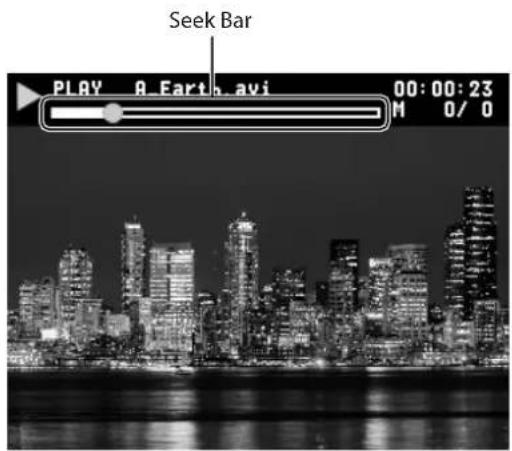
- Seek Bar This is displayed when [INFO] button is pressed twice. This displays progress of the currently playing file.
You can touch and move the green dot to change location to play.
NOTE
While the seek bar is displayed, you cannot adjust size/position of the inset screen of picture in picture using touch panel. Close the seek bar when you use touch panel for size/position adjustment (p. 35).
[INFO] x 1 [INFO] x 2
10. USER LOGO Button (p. 53)
At times such as during intervals in a band performance, you can output a logo stored in the VR-5. Pressing this makes it light up and switches from video output to output of the logo. Pressing it a second time makes it go dark and returns to the video output.
* Even during logo output, you can apply a fade-in or fade-out by operating the [VIDEO OUT] dial.
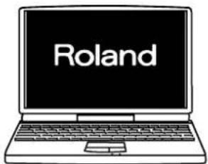
* By default, the logo stored in the unit is the "Roland" logo shown below. Outputting a user logo requires overwriting the logo data in the VR-5. Refer to "Registering a User Logo" (p. 53).

Output Section
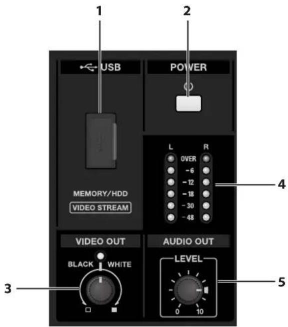
1. USB Port (p. 51)
You can use this to output the results of video and audio mixing on the VR-5 the connected computer. You can also connect USB memory to copy files recorded to SD card.
* Open the sliding cover only when you are using the USB port. When this is not in use, be sure to keep the sliding cover closed to protect the connector inside.
* When connecting the VR-5 and a computer, be sure to use the included USB cable (type A - type A).
* By default, the USB port is set to output video and audio mixing results to computer. Connecting a USB memory device and copying recorded files requires setting the USB mode. At the SYSTEM menu, select [VIDEO/AUDIO], then select [USB MODE]. When you copy the recorded files from SD card to USB memory, change the mode to [STORAGE]. About mode setup, refer to "Menu Operations and menu List" (p. 60), "SYSTEM Menu" (p. 64).
2. POWER Button (p. 11)
This switches the power to the VR-5 on and off.
3. VIDEO OUT Dial (p. 33)
This applies a fade-in or fade-out to the final output of the VR-5. Turning the dial counterclockwise applies a black fade, and turning clockwise applies a white fade. Applying a fade makes the indicator above the dial flash.
4. LEVEL Indicator
Normally, this displays the volume level of the final audio output. During recording, it displays the recording level. If [OVER] lights up, the audio being output or recorded may experience distortion. Turn the [AUDIO OUT LEVEL] dial counterclockwise to lower the volume level.
5. AUDIO OUT LEVEL Dial (p. 33)
Normally, this adjusts the volume level of the final audio output. During recording, it simultaneously adjusts the level of final output and the recording level.
Audio Mixer Section
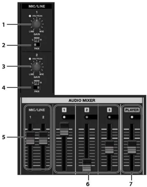
1. GAIN Dial and SIG/PEAK Indicator for MIC/LINE 1
Use the [GAIN] dial to adjust the input sensitivity for the MIC/LINE 1 connectors. Adjust this to match the output from a connected microphone or external mixer.
When input is present, the [SIG/PEAK] indicator lights up green. It lights up red when the input level is too high. If this happens, the output may experience distortion. Lower the input sensitivity.
2. PAN Switch for MIC/LINE 1
This sets the stereo position for MIC/LINE 1 input. You can make the following three types of settings.
• L This sets the position at the left.
• MONO This sets the position at the center.
• R This sets the position at the right.
3. GAIN Dial and SIG/PEAK Indicator for MIC/LINE 2
Use the [GAIN] dial to adjust the input sensitivity for the MIC/LINE 2 connectors. The indicator is the same as for MIC/LINE 1.
4. PAN Switch for MIC/LINE 2
This sets the stereo position for MIC/LINE 2 input. The settings are the same as for MIC/LINE 1.
5. MIC/LINE 1/2 Faders
These adjust the levels of the audio inputs from MIC/LINE 1 and 2.
6. 1 - 3 Faders
These adjust the levels of the audio inputs from AUDIO INPUT connectors 1 through 3.
* Independent adjustment of left and right is not possible.
7. PLAYER Fader
This adjusts the level of the audio played back from an SD card.
Video Select Section
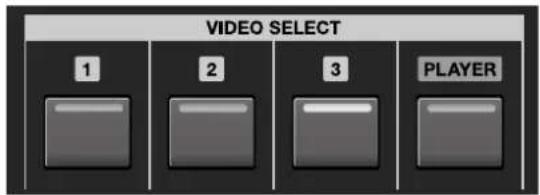
Use these when you want to switch video sources ([1] through [3] and [PLAYER]) using buttons rather than the touch panel.
Video Effects Section
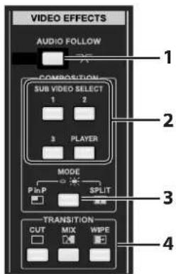
1. AUDIO FOLLOW Button (p. 31)
Pressing this makes the button light up and links audio output/mute with video switching.
2. SUB VIDEO SELECT Buttons (p. 34, p. 36)
These choose the sub video when you are carrying out two-screen compositing using Picture-in-Picture (PinP) or split (SPLIT). The pressed button lights up and the selected channel becomes the sub video. The location where the sub video is displayed varies according to the mode.
• PinP
The sub video is displayed as an inset screen.
• SPLIT
The sub video is displayed at the right or at the bottom.
3. MODE Button (p. 34, p. 36)
• PinP
When the button is dark, the Picture-in-Picture mode is enabled, and an inset screen overlays on the background.
• SPLIT
When the button is illuminated, the split mode is enabled, and the screen is split and two-screen compositing is carried out. This is useful for comparing two camera angles on single screen.
4. TRANSITION Buttons (p. 28)
These choose the transition effect. The effect selected here is applied when switching between video sources.
* When you select [CUT], no transition effect is applied. Selecting [MIX] or [WIPE] applies a transition effect.
PC INPUT Section
Using the features in this section lets you perform compositing with a logo or text input from a computer superimposed on the video, as shown below. This type of processing is called "key compositing."
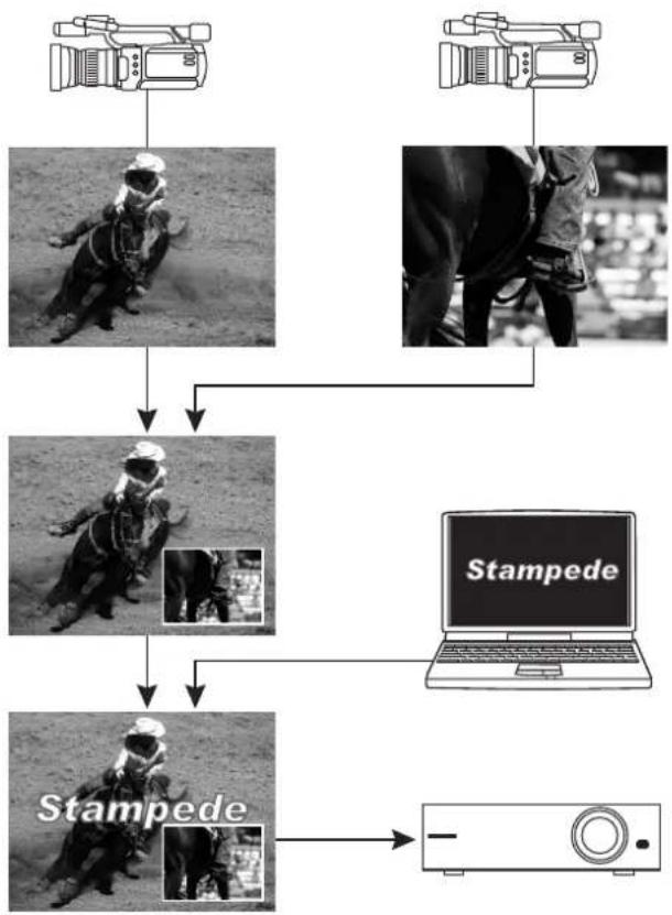
flowchart
graph TD
    A["Camera"] --> B["Rear of a person in motion"]
    C["Camera"] --> D["Rear of a person in motion"]
    B --> E["Player in racing suit"]
    D --> E
    E --> F["Stampede"]
    F --> G["Laptop with 'Stampede'"]
    G --> H["Monitor"]
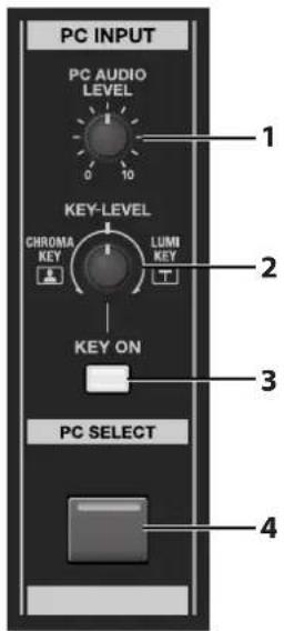
1. PC AUDIO LEVEL Dial
This adjusts the level of the audio input from a computer.
2. KEY LEVEL Dial (p. 39)
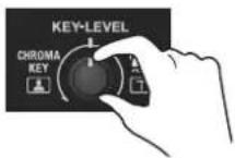
This adjusts the degree of the extraction (removal) in key compositing. At the center position, no extraction occurs at all. (The background is not visible.) The extracting color for key compositing differs according to the direction you turn this dial.
- CHROMA KEY
Turning this counterclockwise enables compositing using a chroma key. Blue or green backgrounds are extracted.
• LUMI KEY Turning the control clockwise enables compositing using a luminance key. Black or white backgrounds are extracted.
* Turning the dial all the way clockwise or counterclockwise enables complete extraction, and the logo or text is not visible. Turn the dial to find the optimal degree of extraction.
MEMO
By default, the extraction colors are black for luminance key and blue for chroma key. As shown below, this produces attractive compositing of white logos or text on a black background, or yellow logos or text on the blue background. You can use the menus to change the extraction color. Refer to "Menu Operations and Menu List" (p. 60), "VIDEO MIX Menu > KEY SETUP" (p. 63).
3. KEY ON Button (p. 38)
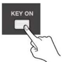
This selects whether key compositing is applied to input from the computer or not. Pressing the button makes it light up, and key compositing is applied. When you want to display illustrations, photographs, and the like from the computer just as they are, with no compositing, leave the button dark.
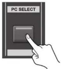
4. PC SELECT Button (p. 39)
Pressing the button makes it light up, and the image input from the computer is output.
When the [PC SELECT] button is dark, only the video-mix results are output.
Recorder Section
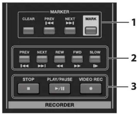
1. Marker Buttons (p. 45)
These add markers to a file for playback. Adding markers lets you carry out indexing quickly during playback.
2. Search/Slow Buttons (p. 44, p. 46)
Use these for searching of desired scenes during playback or for slow playback.
• PREV
When a movie or audio file is selected, pressing this once jumps to the start position of the currently selected playback file. Pressing it twice calls up the file just before the currently selected playback file.
When a still picture is selected, pressing this once calls up the file just before the currently selected file.
The files are arranged by file name (in numerical and alphabetical order).
• NEXT
This calls up the file just after the currently selected playback file.
- REW
This performs rewind playback. With each press increasing the speed in the sequence of 1.5X, 3X, 8X, and 16X. Pressing the button while rewinding at 16X speed returns to normal playback.
• FWD
This performs fast-forward playback. With each press increasing the speed in the sequence of 1.5X, 3X, 8X, and 16X. Pressing the button while fast-forward playback at 16X speed returns to normal playback.
* When a still image file is selected, REW and FWD buttons have no effect.
For information on how to use the [SLOW] button, refer to "Slow Playback" (p. 46).
3. Record/Playback Control Buttons (p. 50)
These start and stop recording or playback.
File Select Section
These select the type of file to play from an SD card. The pressed button lights up, and a list of files that you can play appears on the SETUP/PREVIEW MONITOR.
• VIDEO This selects movie files.
• PICTURE This selects still image files.
• AUDIO This selects audio files.
Rear Panel
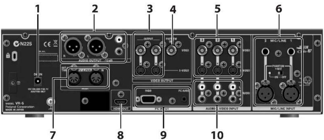
For information about connecting sources and output devices, refer to "Connecting External Equipment" (p. 23).
1. DC IN Jack (p. 10)
This is for connecting the included AC adapter.
* Use the cord hook to secure the AC adapter cord in place.
2. AUDIO OUTPUT Connectors
These output the audio-mix results. Connect output equipment (such as an amplifier or speakers) or recording equipment (such as a video recorder) here.
* The same audio is output from the XLR connectors and RCA connectors. The XLR connectors are balanced, and the RCA connectors are unbalanced.
3. VIDEO OUTPUT Connectors
These output the video-mix results. Connect output equipment (such as a projector or display monitor) or recording equipment (such as a video recorder) here.
4. PREVIEW OUT Connector
This outputs the same four split picture displayed on the SETUP/PREVIEW MONITOR. Connect a monitor to this when you want to view the picture on a large screen or view the picture while displaying menus.
5. VIDEO INPUT Connectors
Use these to connect video cameras or other source equipment.
* These include S-Video and composite (BNC) connectors. When S-Video and composite are input simultaneously on the same channel, the S-Video input takes priority.
6. MIC/LINE INPUT Connectors
These are for connecting microphones or an external audio mixer.
* These include balanced XLR and TRS connectors. When XLR and TRS inputs are made simultaneously on the same channel, the TRS input takes priority.
* You can supply +48 V phantom power from the XLR connectors. Connect condenser microphones or other devices requiring +48 V phantom power to the XLR connectors.
* For information on connecting microphones or an external audio mixer, refer to "Connecting Audio Equipment" (p. 25).
7. MIDI IN and OUT/THRU Connectors
You can connect an external MIDI device and use it to remote control the VR-5. Refer to "Remote Control" (p. 66).
8. HDMI OUT Connector
You can use this to connect HDMI equipment and display digital output of the video and audio mix results.
9. PC INPUT Connectors
You can connect a computer and input logos, text, or images.
* You can also input computer audio.
* For information on making the connections, refer to "Connect a Computer" (p. 24).
10. AUDIO INPUT Connectors
These are for connecting the audio output of video players or other source equipment.
Front Panel
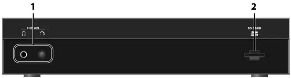
1. PHONES Jack and LEVEL Dial
The PHONES jack outputs the mixed audio output to headphones. Headphone volume is controlled by the LEVEL dial.
MEMO
You can use the menu to make the volume level adjusted by this LEVEL dial independent of volume control using the AUDIO OUT LEVEL dial on the top panel. Refer to "Menu Operations and Menu List" (p. 60), "SYSTEM Menu > VIDEO/AUDIO > PHONES OUTPUT" (p. 64).
2. SD CARD Slot
Insert the SD card here. You can play files (movie, still image, audio) from the SD card into VR-5's video/audio mixers. You can also capture the video and audio mixed output to the SD card.
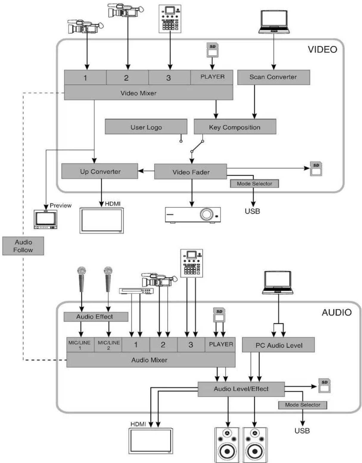
Signal Flow
Signal flow inside the VR-5 is as shown in the figure below.
flowchart
graph TD
    subgraph Video
        A["Monitor"] --> B["1"]
        C["Camera"] --> D["2"]
        E["Camera"] --> F["3"]
        G["Monitor"] --> H["3"]
        I["Monitor"] --> J["4"]
        K["Monitor"] --> L["5"]
        M["Monitor"] --> N["6"]
        O["Monitor"] --> P["7"]
        Q["Monitor"] --> R["8"]
        S["Monitor"] --> T["9"]
        U["Monitor"] --> V["10"]
        W["Monitor"] --> X["11"]
        Y["Monitor"] --> Z["12"]
        AA["Monitor"] --> AB["13"]
        AC["Monitor"] --> AD["14"]
        AE["Monitor"] --> AF["15"]
        AG["Monitor"] --> AH["16"]
        AI["Monitor"] --> AJ["17"]
        AK["Monitor"] --> AL["18"]
        AM["Monitor"] --> AN["19"]
        AO["Monitor"] --> AP["20"]
        AQ["Monitor"] --> AR["21"]
        AS["Monitor"] --> AT["22"]
        AU["Monitor"] --> AV["23"]
        AW["Monitor"] --> AX["24"]
        AY["Video Mixer"] --> B
        AZ["User Logo"] --> BA
        BB["Key Composition"] --> BC
        BD["Up Converter"] --> BE
        BF["Video Fader"] --> BG
        BH["Mode Selector"] --> BI
        BJ["USB"] --> BK
    end

    subgraph Audio
        BD --> BK
        BL["Audio Effect"] --> BM["MIC/LINE 1"]
        BL --> BN["MIC/LINE 2"]
        BL --> BO["Audio Mixer"]
        BL --> BP["Audio Level/Effect"]
        BL --> BQ["Player"]
        BL --> BR["PC Audio Level"]
        BL --> BS["Mode Selector"]
        BT["HDMI"] --> BU
        BV["Laptop"] --> BW
    end

    subgraph AudioFollow
        BI --> BX
        BX --> BY
    end

    subgraph Audio
        BX --> BZ
        BX --> BW
    end

    style Video fill:#f9f,stroke:#333
    style Audio fill:#bbf,stroke:#333
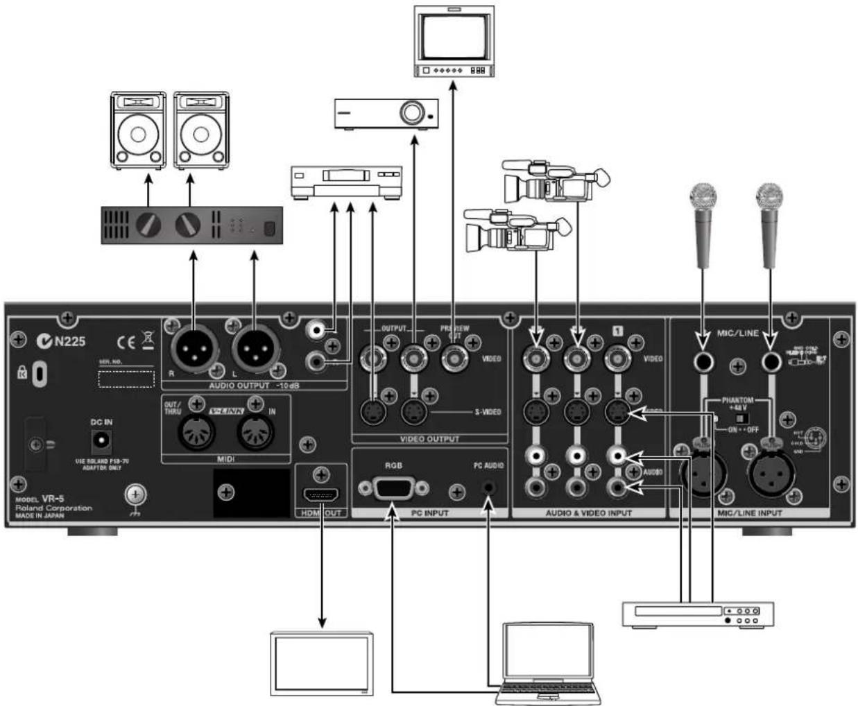
You connect external equipment as shown below.
* To prevent malfunctions and/or damage to speakers or other devices, always turn down the volume, and turn off power on all devices before making any connections.
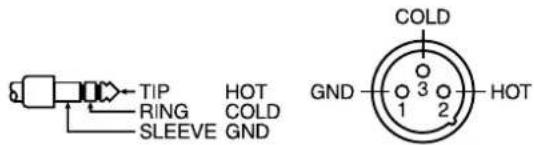
This unit is equipped with balanced XLR/TRS type jacks. Wiring diagram for these jacks are shown below. Make connections after checking the wiring diagrams of other equipment you intend to connect.
Howling (feedback) can occur depending on the location of microphones relative to speakers. This can be remedied by :
- Changing the orientation of microphone(s).
- Relocating microphone(s) at a greater distance from speakers.
- Lowering volume levels.
Connecting Source Equipment
NOTE
Although frame synchronizers are built into the VR-5, you may occasionally experience a dropped or skipped frame. The likelihood of experiencing a dropped or skipped frame depends largely on your video sources. Be sure that your video sources provide strong, stable video signals in order to minimize the possibility of dropped frames.
Connecting Video Equipment
Connect video cameras, DVD players, and other source equipment to VIDEO INPUT connectors 1 through 3. Composite (BNC) and S-Video connectors are provided, and when inputs are made through both types simultaneously, the S-Video input takes priority.
* When connecting a device equipped with RCA pin type connectors, use the included conversion plug.
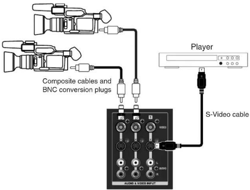
Connect a computer.
Connect the external output of the computer to the RGB connector of PC INPUT. A built-in scan converter converts the incoming RGB signal to a video signal.
* The resolutions supported by the internal scan converter are as shown in the table.
When connecting audio output of the computer to the PC AUDIO jack, use a stereo-mini cable.
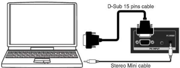
Supported Resolutions
| 640 x 480 / 120Hz | 800 x 600 / 120Hz |
| 1024 x 768 / 80Hz | 1152 x 864 / 75Hz |
| 1280 x 1024 / 75Hz | 1600 x 1200 / 60Hz |
* The refresh rate is the maximum value of each resolution.
* The PC INPUT connector on the VR-5 is D-Sub 15-pin. Using a conversion cable makes it possible to make DVI connections. A D-Sub 15-pin to DVI cable is not included. Please purchase one separately.
MEMO
When displaying moving images from computer input, flicker or other picture corruption may occur. This is called [tearing], and does not indicate an equipment malfunction.
Connecting Audio Equipment
Connecting Playback Equipment
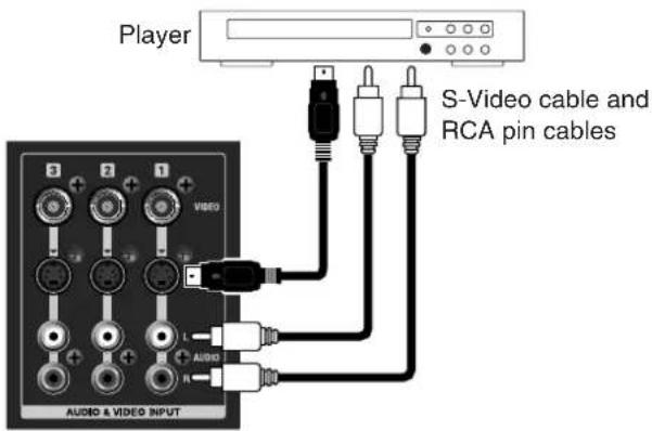
Connect the audio output from video players, CD players, and other devices to the AUDIO INPUT connectors. When video output from a player is connected to a VIDEO INPUT connector, make the connection to the AUDIO INPUT connectors that have the same number.
* When making the connection, be careful to connect the left and right lines correctly.
Connecting Microphones
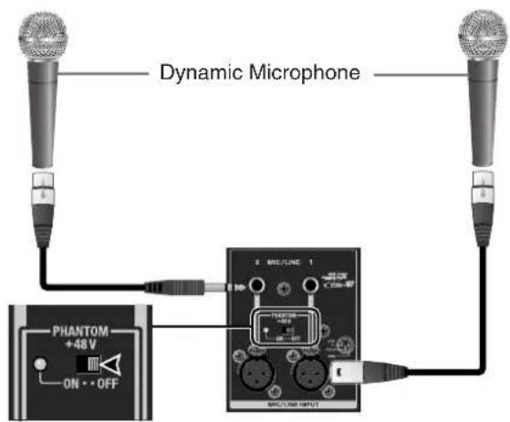
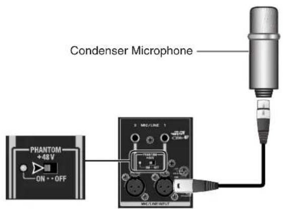
Connect microphones to the MIC/LINE INPUT 1 and 2 connectors. MIC/LINE INPUT provides two types of connectors (TRS and XLR), and when connections are made to both at the same time, the TRS connection takes priority. When you are connecting a condenser microphone or other device that requires a supply of +48 V phantom power, make the connection to an XLR connector, and set the [PHANTOM +48V] switch to ON. When the switch is set to ON, the indicator next to the switch lights.
* Supplying +48 V phantom power to the TRS connectors is not possible.
* Supplying +48 V phantom power to just one connector (1 or 2) and not the another is not possible. When the switch is set to ON, power is supplied to both connectors.
NOTE
When you are connecting equipment that requires phantom power, connect the equipment first, then set the [PHANTOM +48V] switch to ON.
NOTE
When you are connecting a dynamic microphone or other device that does not require power supply, be sure to set the [PHANTOM +48V] switch to OFF. Making the connection while the switch is left set to ON may cause malfunction. (Phantom power on the VR-5: +48 V DC/maximum 14 mA on each channel)
Connecting an External Audio Mixer
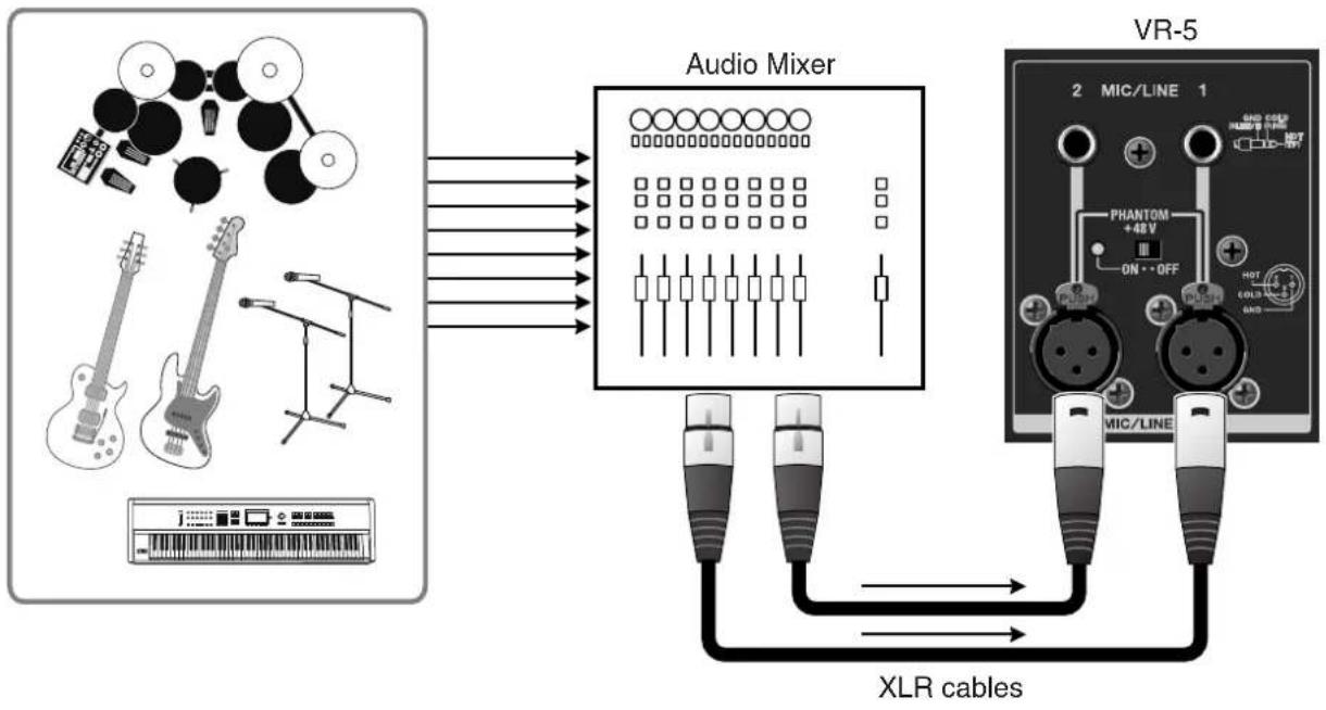
When the number of audio channels is large, such as when you are recording a band performance, connect to the MIC/LINE INPUT 1 and 2 connectors via an external audio mixer.
flowchart
graph LR
    A["Audio Mixer"] -->|Signal| B["XLR cables"]
    B --> C["VR-5 Microcontroller"]
    subgraph Audio Mixer
        D["Radio buttons: 1, 2, 3, 4, 5, 6, 7, 8, 9, 10, 11, 12, 13, 14, 15, 16, 17, 18, 19, 20"]
    end
    D --> E["Pin 1: 1, 2, 3, 4, 5, 6, 7, 8, 9, 10, 11, 12, 13, 14, 15, 16"]
    E --> F["Pin 2: PHANTOM +48V"]
    F --> G["Pin 3: ON+OFF"]
    G --> H["Pin 4: HOT"]
    H --> I["Pin 5: COLOR"]
    I --> J["Pin 6: MAX"]
    J --> K["Pin 7: PHANTOM +48V"]
    K --> L["Pin 8: ON+OFF"]
    L --> M["Pin 9: HOT"]
    M --> N["Pin 10: COLOR"]
    N --> O["Pin 11: MAX"]
    O --> P["Pin 12: MAX"]
    P --> Q["Pin 13: MAX"]
    Q --> R["Pin 14: MAX"]
    R --> S["Pin 15: MAX"]
    S --> T["Pin 16: MAX"]
    T --> U["Pin 17: MAX"]
    U --> V["Pin 18: MAX"]
    V --> W["Pin 19: MAX"]
    W --> X["Pin 20: MAX"]
NOTE
The nominal input level of the VR-5 is -10 dBu. When you are connecting an external audio mixer that has a high output level, such as +4 dBu, connect it via an attenuator.
Connecting Output Equipment
Connecting a Projector or Recorder
Connect projectors and recorders to the VIDEO OUTPUT connectors. The VIDEO OUTPUT connectors include composite (BNC) and S-Video connectors, and both types output the same mixed output video stream.
* When connecting a device equipped with RCA pin type connectors, use the included conversion plug.
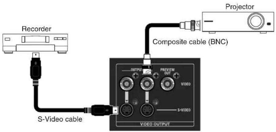
Connecting an Amplifier/Speakers or Recorder
Connect an amplifier/speakers or a recorder to the AUDIO OUTPUT connectors. The AUDIO OUTPUT connectors include XLR and RCA connectors, and both types output the same audio.
* The nominal output level of the VR-5 is -10 dBu. Connect equipment that supports input at -10 dBu.
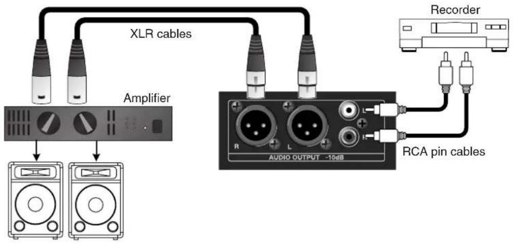
Connecting a Monitor Display
The VR-5 has two types of monitor output connectors.
HDMI OUT Connector
This provides digital output of the video and audio mix results.
* The signal output from the HDMI OUT connector is 480/59.94p (when set to NTSC) or 576/50p (when set to PAL).
* The aspect ratio of HDMI output is stretched from 4:3 to 16:9.
* You can use the menus to select final output or preview output as the source for HDMI output.
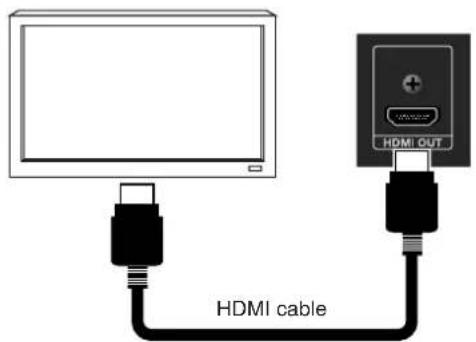
PREVIEW OUT Connector
The same four split preview video shown on the SETUP/PREVIEW MONITOR is displayed. Connect a monitor display when you want to view the preview video on a large screen.
* A monitor connected to the PREVIEW MONITOR connector does not display the menu screen of VR-5.
* When connecting a device equipped with RCA pin type connectors, use the included conversion plug.
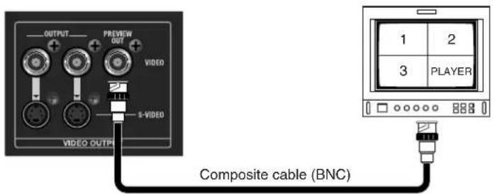
This section describes how to switch (transition) between video sources or mix video sources. It also describes how to mix audio from external audio sources.
Switching the Video
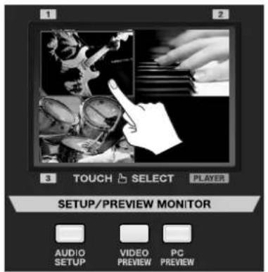
You can switch/mix between external video input sources [1] through [3] by using [VIDEO SELECT] buttons or SETUP/PREVIEW MONITOR touchscreen.
NOTE
If a fade is applied to the final output, the video is not output to a projector or other output device. Adjust the [VIDEO OUT] dial to its center position. For information about fades in final output, refer to "Applying a Fade to Final Video Output" (p. 33).
Using the Touch Panel to Switch the Video
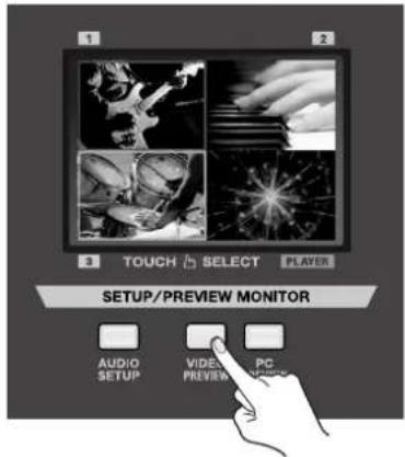
1. Display the input from the source.
Use the View Mode buttons for the SETUP/PREVIEW MONITOR to select [VIDEO PREVIEW]. The inputs from the connected video source are displayed at SETUP/PREVIEW MONITOR [1] through [3]. When the VR-5 starts up, [1] is selected, and a red border is displayed around [1] section.
2. Select a transition effect.
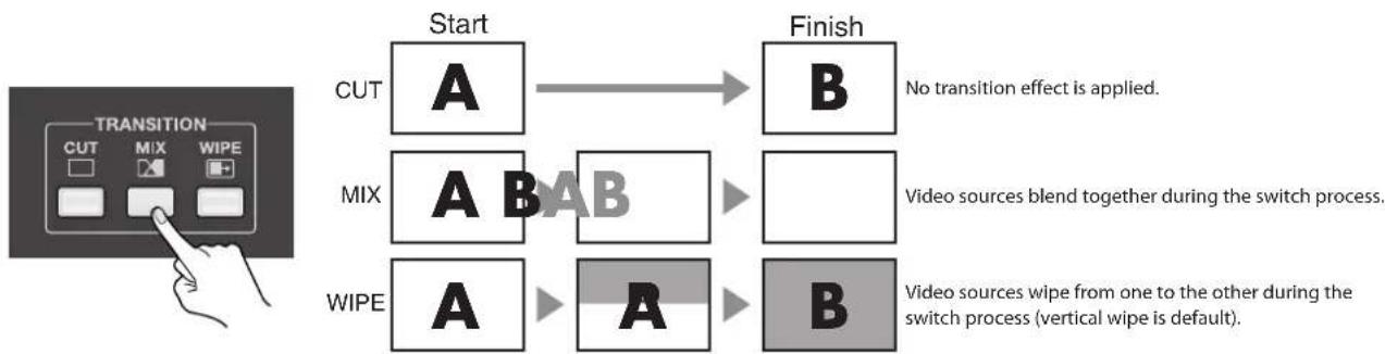
Use the [TRANSITION] buttons to select a transition effect. When you select [CUT], the switch is instantaneous, and no transition effect is applied. If you want to apply a transition effect, select [MIX] or [WIPE].
flowchart
graph LR
    A["Start"] --> B["Finish"]
    C["CUT"] --> D["A"]
    E["MIX"] --> F["A"]
    G["WIPE"] --> H["A"]
    D --> I["B"]
    F --> J["B"]
    H --> K["B"]
• The duration of the transition effect is set at 0.5 seconds by default.
- You can choose from eight types of wipe patterns.
- You can change the direction of the wipe, and also apply soft edges to the wipe.
You can use the menus to modify these items and change the settings for the transition effect. Refer to "Menu Operations and Menu List" (p. 60), "VIDEO MIX Menu > WIPE SETUP > PATTERN" (p. 63).
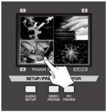
3. Select a different channel.
Use the touch panel to choose a channel other than the one currently selected (the channel displayed with a red border). If you selected [MIX] or [WIPE] in step 2, the transition effect is applied. The newly selected channel is displayed with a green border while the transition effect is being applied. When the applied transition effect ends, the color of the border changes to red.
Using Button Operations to Switch the Video
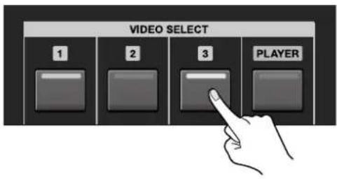
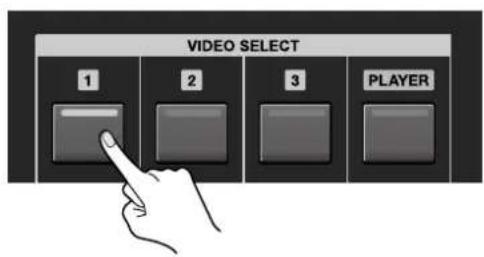
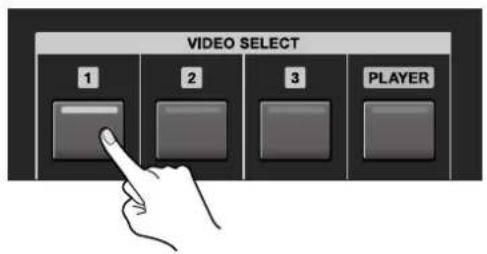
Instead of using the touch panel, you can also switch video by pressing the [VIDEO SELECT] buttons.
The button indicator for the currently selected channel lights up red. The indicator for the newly selected channel flashes green while a transition effect is applied. When the applied transition effect ends, the color of the indicator changes to red, and the indicator stops flashing and lights up steadily.
Adjusting the Volume Balance
Audio sources connected to the MIC/LINE inputs should be set for optimal input level using the [GAIN] dials [1] and [2]. Use the [PAN] switches to set the stereo position. For information on adjusting the input sensitivity and stereo position, refer to "Audio Mixer Section" (p. 16).
NOTE
When the level of the final output has been lowered, no audio is output to speakers. Adjust using the [AUDIO OUT LEVEL] dial. For information on adjusting the level of final output, refer to "Adjusting the Volume of the Final Output" (p. 33).
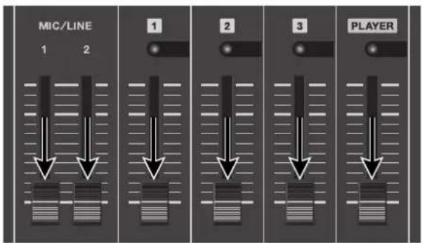
1. Lower all faders completely.
Before performing audio mixing, lower all faders to the bottom.
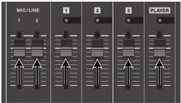
2. Raise the volume level of each channel.
Gradually raise the faders for the respective channels. Raise the faders for all channels that have input.
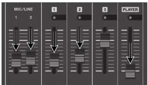
3. Adjust the volume balance for the channels.
Leave the fader untouched for the channel you want to make prominent, and lower the faders for the other channels.
Linking Audio to Video
[AUDIO FOLLOW] causes the audio associated with a video source to become prominent when that video source is selected. Only the audio input on the same channel as the selected video channel is output — other channels are automatically muted.
NOTE
The positions of the faders do not change automatically when the link feature is activated. Audio sources will be automatically output at the currently set fader level, or they will be muted.
1. Adjust the audio on the respective channels.
Raise and lower the faders for the channels to adjust them to the volume level you want to output.
2. Switch on the link feature.
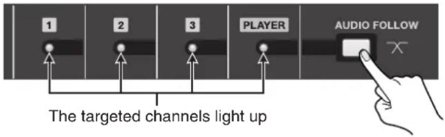
Press the [AUDIO FOLLOW] button to make it light up. The indicators for the channels targeted by the link feature light up. Pressing the button a second time makes it go dark and switches off the link feature. At the same time, the indicators for the channels also go dark.
* By default, all channels are selected as target channels. You can also use menu operations to remove specific channels from the group of targets. Refer to "Menu Operations and Menu List" (p. 60), "AUDIO MIX Menu > AUDIO INPUT" (p. 64).
3. Switch the video channel.
Use the procedure in "Switching the Video" (p. 28) to switch the channel. Only the audio input on the same channel as the selected video is output — other channels are muted. The output at this time is at the volume level you set in step 1. Also, the indicator for selected output channel starts to flash.
* Audio cross-fade is applied for the length of time set for transition effects. By default, this is set at 0.5 seconds. You can use the menus to change the time. Refer to "Menu Operations and Menu List" (p. 60), "VIDEO MIX Menu > TRANSITION SETUP > TRANSITION TIME" (p. 63).
Applying Effects to Audio
You can apply effects to the audio before output. You can apply the following effects.
For MIC/LINE 1 and 2
- HIGH PASS This cuts the low band, passing only the high band. This is effective in removing low-frequency noise.
- NOISE GATE This attenuates signals below a certain level. Use this when you want to suppress low-level sound or noise.
- EQ Lo/Hi You can use this to attenuate or emphasize low-band (Lo) or high-band (Hi) signals.
For Final Output
- NOISE SUPPRESSOR This cancels signals during times of no input, for output of clear audio.
- ENHANCER This adds harmonics to adjust or accent the tone quality.
- MASTER Lo/Hi This corrects for distortion in the low end (Lo) or high band (Hi).
* You can apply above effects when [MASTERING EFF] has been switched on.
In addition to these, you can also apply [LIP SYNC DELAY] to delay audio output to allow lip-syncing with the video. From the SYSTEM menu, choose [VIDEO/AUDIO], then select [LIP SYNC DELAY]. Increasing the setting value makes the delay longer.
1. Display the AUDIO MIX menu.
Use the View Mode buttons for the SETUP/PREVIEW MONITOR to select [AUDIO SETUP]. The audio-related menu appears.
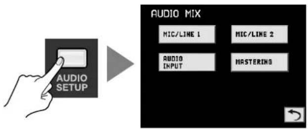
flowchart
graph LR
    A["Hand with 'AUDIO SETUP'"] --> B["→"]
    B --> C["AUDIO MIX"]
    C --> D["MIC/LINE 1"]
    C --> E["MIC/LINE 2"]
    C --> F["AUDIO INPUT"]
    C --> G["MASTERING"]
2. Select the target channel.
Select the channel where you want to apply the effect. Select [MIC/LINE 1], [MIC/LINE 2], or [MASTERING].
MEMO
Selecting [AUDIO INPUT] lets you choose the target channel for the link feature (p. 31).
3. Select the effect to apply.
From among the effects listed on the previous page, select the effect to apply. You can make the selection by touching the touch panel. The selected effect is displayed with a red border around it.
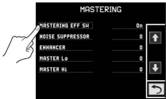
4. Switch the effect on or off, or adjust it.
Turn the [VALUE] dial to switch the effect on or off. Adjust the amount of effect to be applied.
MEMO
You can return to previous screen by touching the "Return" symbol.
5. Go back to the original screen.
Press the [VIDEO PREVIEW] button to exit the menu screen. This returns the display to the original four split screen.

Applying a Fade to Final Video Output
You can apply a fade-in or fade-out to the final output by operating a dial. This applies a white or black fade-out at times when you want to fade the video output, such as during intervals in a band performance.
Fade Out
Turning the [VIDEO OUT] dial clockwise applies a white fade-out, and turning it counterclockwise applies a black fade-out. Applying a fade makes the indicator above the dial flash.
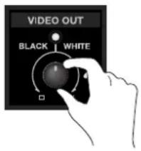
Fade In
Return the [VIDEO OUT] dial to its center position. The indicator stops flashing and lights up steadily, and video output resumes.
Adjusting the Volume of the Final Output
You can adjust the volume level of the final output by operating a dial. You carry out this operation while watching the MASTER indicator.
1. Check the volume level of the final output.
See the MASTER indicator to check the volume level. If [OVER] lights up, the volume level may be excessive, resulting in distortion. If only the indicators up to around [-48] or [-30] light up, the volume level may be insufficient. This might worsen the signal-to-noise ratio, resulting in poor-quality speaker output.
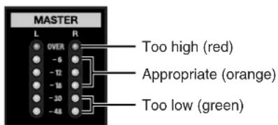
2. Adjust the volume level.
Turn the [AUDIO OUT LEVEL] dial to adjust the volume level. A suitable level is where [-18] to [-6] light up during moments of maximum loudness.
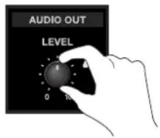
NOTE
If the volume level of speaker output is not suitable even after adjustment into the [-18] to [-6] range, adjust the volume for the speakers or the amplifier. Once your VR-5's [AUDIO OUT LEVEL] is set properly, changing it again to accommodate your speaker or amp settings may worsen the sound quality. It is best to set [AUDIO OUT LEVEL] properly, then adjust the volume setting of your speaker or amp.
Two-screen Composition Using Picture-in-Picture
Compositing that displays an inset screen on a background is called "Picture-in-Picture" (PinP).
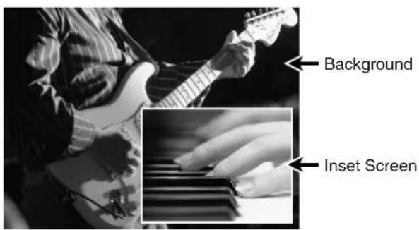
MEMO
By default, no shadows are added to the inset screen, but you can use the menus to add them. Refer to "Menu Operations and Menu List" (p. 60). A white border is added by default.
MEMO
By default, the size of the inset screen is about one-third the size of the background, both vertically and horizontally. You can use the menus to change the size of the inset screen. Refer to "Menu Operations and Menu List" (p. 60). For information on how to adjust the position of the inset screen, refer to "Adjusting the Position and Size of the Inset Screen" on the next page.
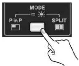
1. Select the PinP mode.
Use the [MODE] button to select [PinP]. When the button is dark, the PinP mode is enabled. When it lights up, the SPLIT mode is enabled.
2. Select the background.
Use the touch panel for the [SETUP/PREVIEW MONITOR] or the [VIDEO SELECT] buttons to select the channel for the background.
3. Select the channel for the inset screen.
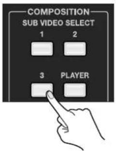
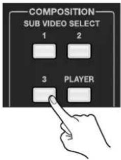
Press a [SUB VIDEO SELECT] button to select the channel for displaying inside the inset screen. Pressing a button makes it light up, and the inset screen is displayed.
NOTE
Applying an effect (MIX or WIPE) for switching the channel of inset screen is not possible. The switching is made using a cut.
4. Make the inset screen disappear.
Press the button you selected in step 2 again. The button goes dark and the inset screen disappears.
MEMO
The duration of the fade when the inset screen appears or disappears is the duration set for transition effects. By default, this is set at 0.5 seconds. You can use the menus to change the time. Refer to "Menu Operations and Menu List" (p. 60), "VIDEO MIX Menu > TRANSITION SETUP > TRANSITION TIME" (p. 63).
Adjusting the Position and Size of the Inset Screen
You can use the touch panel for the OUTPUT MONITOR to adjust the position of the inset screen. Display the inset screen, then slide your finger over the surface of the touch panel.
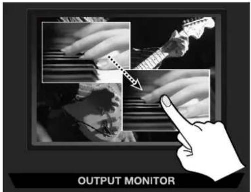
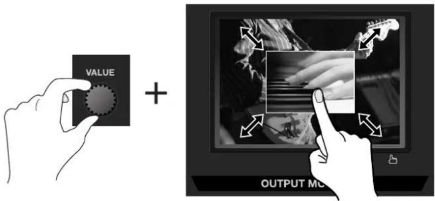
You can also adjust size of the inset screen. When you adjust size of the inset screen, keep touching the inset screen on OUTPUT MONITOR and turn the [VALUE] dial.
Two-screen Composition Using Split
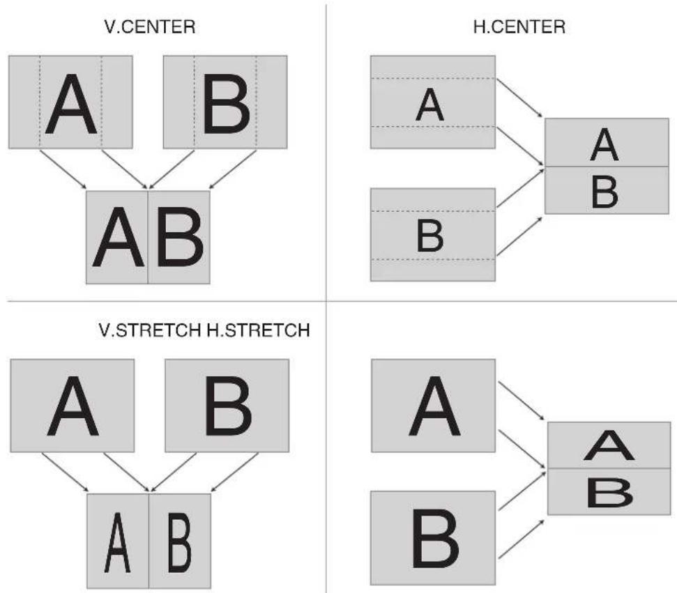
On the VR-5, in addition to Picture-in-Picture, you can also perform two-screen compositing using Split. Split has the four patterns shown below.
* The names of the menu items are shown in the figures below. By default, "V. CENTER" is selected as the split pattern. You can use the menus to change this to a different pattern. Refer to "Menu Operations and Menu List" (p. 60), "VIDEO MIX Menu > SPLIT > PATTERN" (p. 63).
1. Select the SPLIT mode.
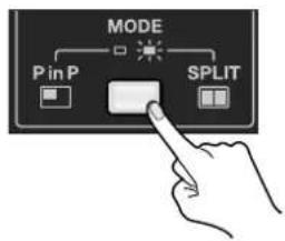
Use the [MODE] button to select [SPLIT]. When the button is dark, the PinP mode is enabled. When it lights up, the SPLIT mode is enabled.
2. Select the channel to display on A-side.
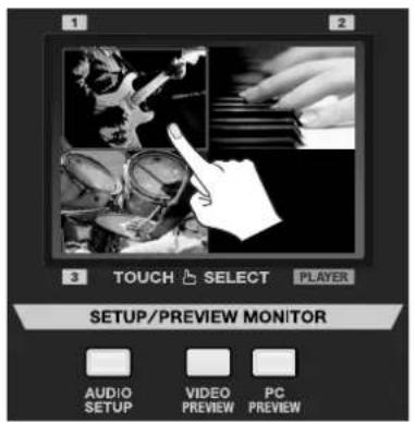
Use the touch panel for the [SETUP/PREVIEW MONITOR] or the [VIDEO SELECT] buttons to select the channel to display on A-side in the figures.
3. Select the channel to display on B-side.
Press a [SUB VIDEO SELECT] button to select the channel to display on B-side in the figures. Pressing a button makes it light up, and the picture is displayed on B-side.
NOTE
Applying an effect (MIX or WIPE) for switching the channel of B-side is not possible. The switching is made using a cut. Applying fade when the B-side picture appears or disappears is also not possible.
4. Quitting the split view.
When all [SUB VIDEO SELECT] buttons go dark, the screen returns from split view to normal display.
Compositing a Logo or Text from a Computer
With the VR-5, you can superimpose a logo or text from a computer onto the mixed video. Arrange the logo or text on a background of a single color such as black or white, then output it from the computer to the VR-5. The process of extracting the background color to leave only the logo or text and then superimposing it onto video is called "key compositing."
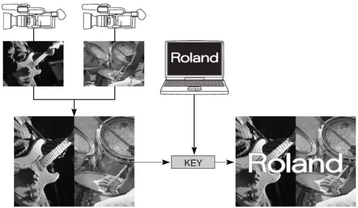
flowchart
graph TD
    A["Camera"] --> C["Key"]
    B["Camera"] --> C["Key"]
    C --> D["Roland"]
    E["Drain"] --> C
    F["Radio"] --> C
    G["Radio"] --> C
MEMO
By default, you can achieve attractive compositing for a white logo or text on a black background like the one shown below.
MEMO
The duration of the fade-in and fade-out for the logo or text is the duration set for transition effects. By default, the fade time is 0.5 seconds. You can use the menus to change the time. Refer to "Menu Operations and Menu List" (p. 60), "VIDEO MIX Menu > TRANSITION SETUP > TRANSITION TIME" (p. 63).
1. Create the background.
Carry out video mixing to create the background image.
2. Switch on the key-compositing feature.
Press the [KEY ON] button to make it light up.
* When [KEY ON] is dark, no compositing with the background is performed.
3. Adjust the degree of extraction.
Turn the [KEY LEVEL] dial to adjust the degree of extraction. Turn it counterclockwise for chroma-key compositing or clockwise for luminance-key compositing. Turn the dial to find the optimal degree of extraction.
* At the center position, no extraction occurs at all. (The background is not visible.)
* Turning the dial all the way clockwise or counterclockwise enables complete extraction, and the logo or text is not visible.
4. Make the logo or text disappear.
Press the [KEY ON] button a second time to make it go dark. The logo or text disappears, and the display returns to output of the video.
Display the Images from Computer Only
When you do not want to composite the images from your computer on the background video, press the [PC SELECT] button to make it light up. The image from your computer is output to full screen. Press the [PC SELECT button] a second time to make it go dark to return to output of the video.
Performing Playback from an SD Card
Video and audio played back from an SD card is sent to the [PLAYER] channel.
* In this manual, "SD card" refers to SDHC cards as well.
flowchart
graph LR
    A["1 TOUCH SELECT PLAYER"] --> B["SD"]
    B --> C["1 2 3 PLAYER"]
    C --> D["3"]
Inserting an SD Card into the Slot
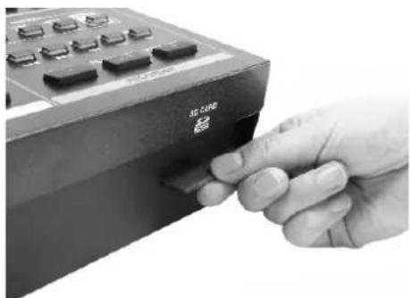
With the power to the VR-5 turned off, orient the SD card so that the side printed with the label faces up, and carefully insert the SD card into the slot at the front panel—until it is firmly in place. If the SD card is correctly recognized and ready for use, the message "SD Card is ready for use" appears on the OUTPUT MONITOR.
* When inserting the SD card, be careful to orient the front and back correctly and insert it in the correct direction, and insert the card firmly, all the way into the slot. Never insert using undue force.
* Never insert or remove the SD card while the power of this unit is turned on. Doing so may corrupt the data on the SD card.
When ejecting the SD card, press the portion of the SD card that protrudes from the slot. This releases the lock and pushes the SD card out from the slot.
natural_image
Close-up of a hand inserting a 3D CUBB button into a black electronic device (no visible text or symbols on the device itself)NOTE
Observe the following precautions regarding the SD cards that you use.
• The VR-5 supports only SD cards and SDHC cards of class 4 or higher. Be sure to use cards of class 4 or higher.
- The VR-5 is compatible with SD cards and SDHC (High Capacity) cards, but does not support SDXC (eXtended Capacity) cards.
- Operation has been tested for commonly available SD cards, but operation with all SD cards is not assured. Depending on the manufacturer and type of the SD card, correct playback may not be possible. Some types of SD cards from some manufacturers may not work properly on the VR-5.
About the contents included in accessory SD Card
The copyright of contents in accessory SD card (movie data, picture data and sound waveform data) of this product is reserved by Roland Corporation.
Purchasers of this product are permitted to utilize said content for the creating, performing, recording and distributing original visual or musical works. Commercial use is also possible.
Purchasers of this product are NOT permitted to extract said content in original or modified form, for the purposes of distributing recorded medium of said content or making them available on a computer network.
SD Card Folder Structure
SD cards used for playback on the VR-5 have the folder structure shown below. When an SD card is formatted using the VR-5, the folder structure shown below is created automatically. For information on formatting SD cards, refer to "Formatting an SD Card" (p. 48).
NOTE
Please be aware that SD cards that do not have this structure cannot be recognized by the VR-5.
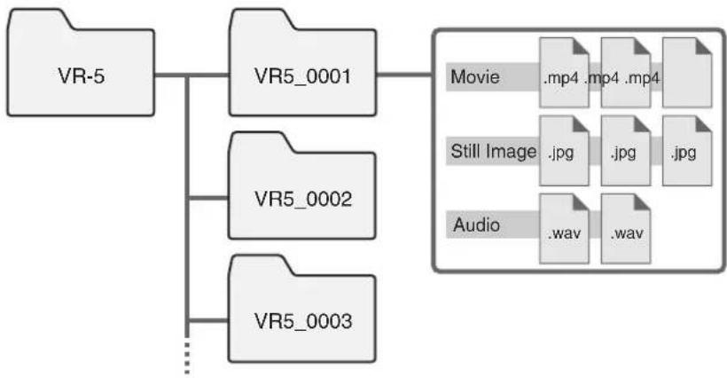
flowchart
graph TD
    A["VR-5"] --> B["VR5_0001"]
    A --> C["VR5_0002"]
    A --> D["VR5_0003"]
    B --> E["Movie .mp4 .mp4 .mp4"]
    C --> F["Still Image .jpg .jpg .jpg"]
    D --> G["Audio .wav .wav"]
Supported File Formats for Playback
To enable playback from an SD card, save the data onto the SD card with the formats described below.
• Movies
Save MPEG-4 Visual data in AVI format or MP4 format.
Set the bit rate at 6 Mbps or lower.
Make the size 720 x 480 pixels (when set to NTSC) or 720 x 576 pixels (when set to PAL).
• Still Images
Save as uncompressed BMP or as JPG.
BMP : Keep the size no more than 2,300 x 1,725 pixels.
JPG: Keep the size no more than 3,600 x 2,700 pixels
• Audio
Save as an uncompressed WAV, or as MP3 at 128 Kbps or lower.
Only 48-kHz sampling is supported.
MEMO
You can download the file-conversion software [VR-5 Image Converter] from the following Roland website. This software converts various types of formats to supported formats of the VR-5.
http://www.rolandsystemsgroup.net/
About Write-protect (LOCK) Feature
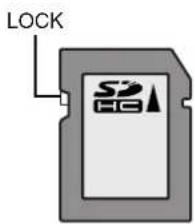
Sliding the write-protect switch on the side of the SD card to "LOCK" makes it impossible to write to the card, enabling protection of the data saved on the card. When saving files or deleting data, slide the write-protect switch to unlock the card.
File Playback
NOTE
Never eject an SD card during playback. Doing so might cause data loss on the SD card. Turning off the power of this unit during playback may cause the same problem.
1. Select the type of file to play.
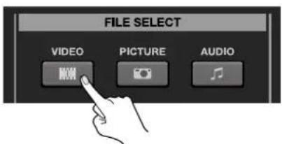
Press one of the [FILE SELECT] buttons to select video (VIDEO), still images (PICTURE), or audio (AUDIO) as the type of file for playback. Pressing one of the buttons displays a list of playable files on the SETUP/PREVIEW MONITOR.
* Inputs from sources do not appear on the SETUP/PREVIEW MONITOR while this menu is displayed. You can use an external preview monitor to view your video sources during menu operation. While inputs are not shown, you can use the [VIDEO SELECT] buttons to switch the video.
* If the SD card is not recognized by the VR-5 or is corrupt, the message [MEDIA FOUND OR DAMAGED] is displayed. If this happens, try ejecting and reinserting the SD card. If the same appears after reinserting, try replacing with a different SD card.
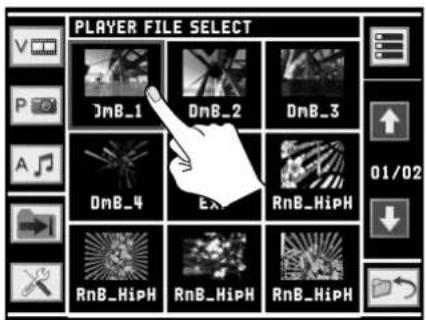
2. Select the file to play back.
Use the touch panel to choose the file to play. Touching the icon for the file you want to play causes a red border to appear around it and puts it in the selected state. By default, playback starts as soon as the file is selected.
* Instead of using the touch panel, you can also perform the same operation using the [VALUE] dial and the [ENTER] button.
* Touching a folder icon displays a list of the files contained in the folder.
3. Quit the menu screen.
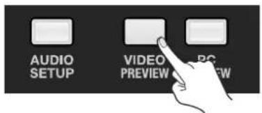
Press the [VIDEO PREVIEW] button to go back to the original four split screen.
* You can also go back to the original screen by pressing the [EXIT] button.
4. Output the played video or audio.
To output video, use the touch panel or the [VIDEO SELECT] buttons to select [PLAYER]. To output audio, go to the audio mixer section and raise the [PLAYER] fader.
* You can change the setting to start playback when the [PLAYER] channel is selected. This is done in the FILE LIST screen (next page).
5. Stop or pause playback.
Pressing the [STOP] button stops playback completely. After pressing [STOP], press [PLAY/PAUSE] again to re-start playback from the beginning of the file.
Pressing the [PLAY/PAUSE] button during playback pauses playback. Press [PLAY/PAUSE] while paused to resume playback from the location where playback was paused.
FILE LIST Screen
The file list screen is displayed by pressing a [FILE SELECT] button. This screen displays a list of contents in the currently selected folder.
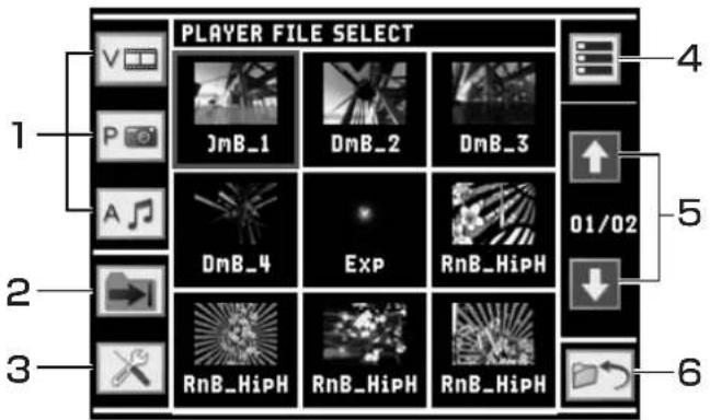
1. File Type Selectors
These select the type of file to display. You can choose video (V), still images (P), or audio (A).
2. Playback Mode Switch
This switches the playback mode. For information on the various modes, refer to the next page.
* This is not displayed when still image (P) is selected.
* You cannot set playback mode individually for each file.
3. Tool
This selects the playback-start mode from below.
- TOUCH ICON START When this is set to [ON], playback starts as soon as a file is selected.
• VIDEO SEL START When this is set to [ON], playback starts as soon as the [PLAYER] channel is selected.
- PLAY + VIDEO SEL When this is set to [ON], [PLAYER] channel is automatically selected as soon as [PLAY/PAUSE] button is pressed.
* When all these are set to [OFF], playback starts when the [PLAY/PAUSE] button is pressed after selecting a file.
* The playback-start mode cannot be set individually for each file.
4. View Mode
This selects a view mode from the following two types.
- Icon View This displays only thumbnails of the files. Nine files are displayed per page.
• List View This displays information on each file (file name, time stamp, and length) next to thumbnail. The display is arranged in four rows.
5. Up/Down
When the files in a folder do not fit on a single page, use the up and down buttons to move forward and backward though the pages. The current page number and the total number of pages are displayed between the up and down buttons.
6. Return
This returns the display to the previous screen.
Playback Modes
On the VR-5, you can select a playback mode. The playback modes cycle through the sequence shown below.
* By default, the mode is set to [ONE SHOT].

flowchart
graph LR
    A["→"] --> B["←"]
    B --> C["→"]
    C --> D["←"]
ONE SHOT LOOP SEQUENTIAL FOLDER LOOP
• ONE SHOT
This plays the selected file one time only (one shot). When playback reaches the end and finishes, the [PLAYER] section of the SETUP/PREVIEW MONITOR turns black.
- LOOP
This performs repeated (loops) playback of the selected file.
- SEQUENTIAL
This plays the files in the selected folder in sequence. When playback of the file immediately before the selected file finishes, the [PLAYER] section of the SETUP/PREVIEW MONITOR turns black.
- FOLDER LOOP
This plays the files in the selected folder in sequence. This sequential playback is repeated (looped).
Search Buttons
You can use these for indexing during playback.
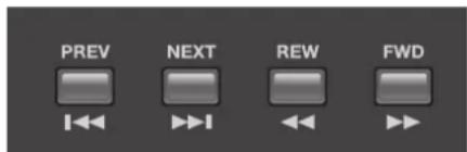
- PREV
When a movie or audio file is selected, pressing this once jumps to the start position of the currently selected playback file. Pressing it twice calls up the file just before the currently selected playback file.
When a still picture is selected, pressing this once calls up the file just before the currently selected file.
The files are arranged by file name (in numerical and alphabetical order).
• NEXT
This calls up the file just after the currently selected playback file.
• REW
This performs rewind playback, with each press increasing the speed in the sequence of 1.5X, 3X, 8X, and 16X. Pressing the button while rewinding at 16X speed returns to normal playback.
• FWD
This performs fast-forward playback, with each press increasing the speed in the sequence or 1.5X, 3X, 8X, 16X, and 32X. Pressing the button while fast-forward playback at 32X speed returns to normal playback.
* When a still image file is selected, REW and FWD have no effect.
Useful Playback Features
Playback Using Markers
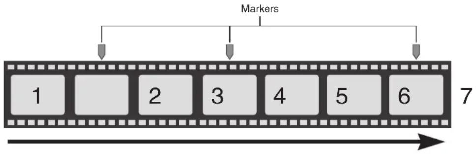
Placing markers in a movie file lets you jump to a desired location in the file with single touch of a button. This feature is useful when you want to skip unnecessary scenes and play only the scenes you want to view.
NOTE
Markers can be placed only in movie files. Placing them in still image or audio files is not possible.
flowchart
graph TD
    A["1"] --> B["2"]
    B --> C["3"]
    C --> D["4"]
    D --> E["5"]
    E --> F["6"]
    G["Markers"] --> H["7"]
1. Place markers in the file.
Select the file where you want to place markers, then start playback. When you reach the location where you want to put a marker, press the [MARK] button. Each time you press [MARK], a new marker will be added at that point.
* You can place up to 99 markers in a single file.
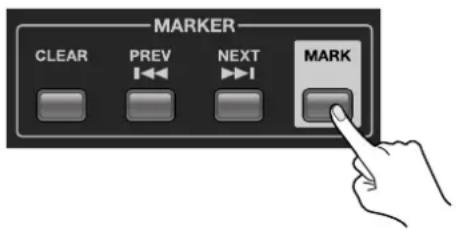
TIP
When you want to set a marker location precisely, use the [PAUSE] button to pause playback, then use the [REW] and [FWD] buttons to find the location for placing the marker.
2. Jump to a marker location.
During playback or while paused, press the [PREV] or [NEXT] jump button. Pressing the [PREV] button jumps to the marker right before the current position, and pressing the [NEXT] button jumps to the next marker after the current position. If playback is in progress, then playback starts from the location of the marker you jumped to. If playback is paused, the image at the location of the marker you jumped to appears in the [PLAYER] section of the SETUP/PREVIEW MONITOR.
* The marker feature cannot be used when playback has been stopped completely by pressing the [STOP] button.
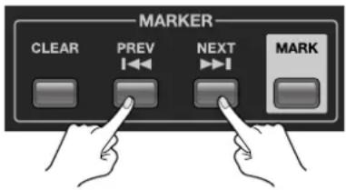
3. Delete a marker.
To delete a placed marker, press the [CLEAR] button. This deletes the marker immediately before the current position.
* To view a list of your markers and selectively delete them, or to delete all markers at once, use the FILE UTILITY menu. Refer to "Editing Makers" (p. 57).
SLOW Playback
With the VR-5, you can perform slow playback at a speed of 75% (x0.75), 50% (x0.50), or 25% (x0.25). The speed of slow playback is displayed on the OUTPUT MONITOR.
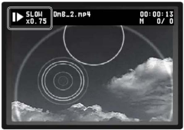
1. Perform playback.
Select the file you want to use for slow playback, and start playback.
2. Perform slow playback.
Press the [SLOW] button. Pressing this slows down the playback speed to 75% (x0.75).
3. Change the speed of slow playback.
Repeatedly pressing the [SLOW] button changes the speed in the sequence of x0.75, x0.50, and x0.25.
4. Return to normal playback.
Pressing the [SLOW] button during playback at x0.25 returns to normal speed (100%, x1.00) playback. When speed returns to normal, the slow playback display disappears.
You can record the final output of the VR-5 to an SD card.
NOTE
However, it is not possible to carry out playback and recording on VR-5 simultaneously. You cannot record the final output during playback on [PLAYER] channel.
About SD card
* In this manual "SD card" refers to SDHC card as well.
NOTE
Observe the following precautions regarding the SD cards that you use.
- You must format your SD card in the VR-5 in order to record. All data on the SD card will be lost. Refer to "Formatting an SD card" (p. 48) for formatting procedure.
• The VR-5 supports only SD cards and SDHC cards of class 4 or higher. Be sure to use cards of class 4 or higher.
• The VR-5 is compatible with SD cards and SDHC (High Capacity) cards, but does not support SDXC (eXtended Capacity) cards. - Operation has been tested for commonly available third-party SD cards, but operation with all SD cards is not assured. Depending on the manufacturer and type of the SD card, correct recording may not be possible.
About Write-protect (LOCK) Feature
Sliding the write-protect switch on the side of the SD card to "LOCK" makes it impossible to write to the card, enabling protection of the data saved on the card. When you record, slide the write-protect switch to unlock the card.
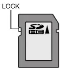
About Recording Time
On the VR-5, you can record continuously until the file size reaches 4GB. When the file size reaches 4GB, the recording is automatically stops. The following recording modes show how much time you can expect in a single 4GB recording.
• TV-XP (6 Mbps) : Approx 80 minutes
• TV-SP (4 Mbps): Approx 2 hours
• TV-LP (2 Mbps) : Approx 4 hours
When 4GB limit is reached, recording stops. If you re-start recording, the re-start process records the newer material in a new file on the SD card.
* If your SD card runs out of available memory, your recording may stop completely prior to reaching 4GB limit.
About File Names of the Recorded Data
The file name will be the date and time when the recording is started (like 11010945). This date/time follows the internal calendar/clock of the VR-5. To name it with precise date/time, set the date and time according to the steps of "Adjusting the Internal Calendar/Clock" (p. 59).
Formatting an SD card
1. Insert the SD card
Insert the SD card for recording to the SD CARD slot on front panel. Refer to "Inserting an SD Card into the Slot" (p. 40)
2. Open SYSTEM menu
Press [MAIN MENU] button to open menu screen. Touch [SYSTEM] to open SYSTEM menu.
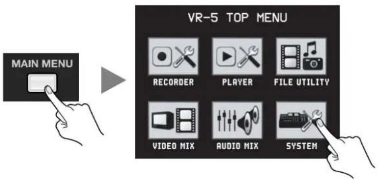
Touch [SD CARD] to enter into SD card setup screen.
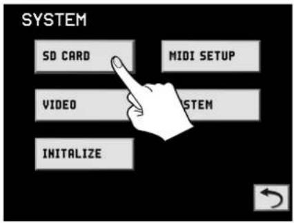
4. Select [FORMAT]
Touch [FORMAT] to open the format dialog.
5. Execute format
Touch [OK] to start formatting the SD card.
When formatting finishes, the message "Please eject the SD Card and insert it again." appears. Eject and reinsert the SD card.
Touching [X] makes the dialog box disappear and cancels formatting.
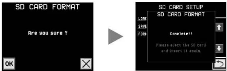
6. Go back to the original screen
Press the [VIDEO PREVIEW] button to go back to the original four split screen.
Selecting a Recording Folder and Recording Mode
1. Open RECORDER menu
Press [MAIN MENU] button to open menu screen. Touch [RECORDER] to open RECORDER menu.
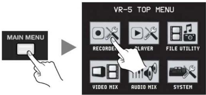
2. Select a recording folder
Touch and select a folder to contain the recorded file.
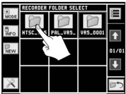
3. Open REC MODE menu and select recording mode
Touch [MODE] to open dialog to select the recording mode. Touch your preferred record mode, then touch [OK] to save the change or touch [X] to cancel the change and exit dialog.
* For details of recording bit rate and recording time, refer to "About Recording Time" (p. 47).
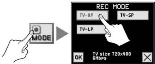
4. Go back to the original screen
Press the [VIDEO PREVIEW] button to go back to the original four split screen.
Record the Final Output
NOTE
When you eject SD card, wait until the [STOP] button stops blinking. DO NOT EJECT SD CARD while [STOP] BUTTON IS BLINKING. Ejection while blinking may destroy data contained the SD card.
1. Output the video and audio to record
Operate the video mixer and audio mixer to output video/audio to record.
2. Standby the recording
Press [VIDEO REC] button to standby the recording. While the unit is standing by, the [VIDEO REC] button flashes.
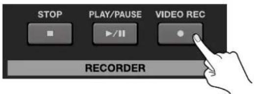
3. Start recording
Press [PLAY/PAUSE] button to start recording. When recording is started, [VIDEO REC] button and [PLAY/PAUSE] button light up.
* The file name will be the date and time when the recording is started (like 11010945). To name with precise date/time, set the date and time according to the steps of "Adjusting the Internal Calendar/Clock" (p. 59).
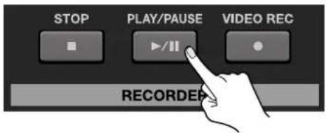
4. Pause recording
Press [PLAY/PAUSE] again to pause the recording. Pausing the recording does not finalize a recorded file. If you want to record multiple scenes in one file, pause the recording.
5. Stop recording
Press [STOP] button to stop recording. This button starts to blink to completely finish the recording and finalize the recorded file. When the finalizing is completed, it stops blinking.
When playing back a recorded file, also wait for the [STOP] button to stop flashing.
* Before ejecting the SD card, be sure to confirm that the [STOP] button has stopped flashing.
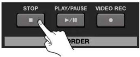
MEMO
You can place markers while recording. The steps to place markers are the same as steps during playback. Refer to "Playback Using Markers" (p. 45). The markers cannot be cannot be deleted until you stop recording to finalize the recorded file.
Connect a computer.
You can output the results of video or audio mixing to a computer connected to the USB port on the VR-5.
NOTE
Prior to connecting to a computer, check the USB mode of your VR-5. At the SYSTEM menu, select [VIDEO/AUDIO], then choose [USB MODE]. Make sure the mode is set to [VIDEO OUT]. By default, it is set to [VIDEO OUT]. However, if you have changed it to [STORAGE] mode, return it to [VIDEO OUTPUT]. Refer to "Menu Operations and Menu List" (p. 60), "SYSTEM Menu" (p. 64) for mode setup.
Supported Operating Systems
You can make connections to computers running the following operating systems.
• Windows XP Home Edition/Professional Edition Service Pack 3 or later
• Windows Vista Service Pack 2 or later
- Windows 7
• Mac OS X 10.6 or later
* Connection and operation of the VR-5 with standard-specification computers running the operating systems described above have been verified, but connection and operation with all equipment satisfying these conditions is not assured. Connection or operation may be impossible due to differences in setting specifications or the usage environment that are specific to the equipment.
To make the connection to a computer, carry out the steps described below.
1. Check the USB mode of the VR-5.
At the SYSTEM menu, select [VIDEO/AUDIO], then choose [USB MODE]. Make sure the mode is set to [VIDEO OUT]. For information on the details of the SYSTEM menu, refer to "SYSTEM Menu" (p. 64).
2. Connect a computer.
Use the included USB cable (type A - type A) to connect the USB port on the computer to the USB port on the VR-5.
NOTE
When making the connections, give attention to the following points.
- Be sure to use the included USB cable (type A - type A).
- Never make the connection through an extension cable or USB hub. Be sure to connect the VR-5 and the computer directly.
- Open the sliding cover only when you are using the USB port. When this is not in use, be sure to keep the sliding cover closed to protect the connector inside.
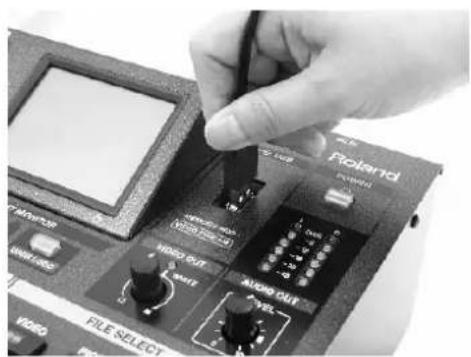
3. Wait for communication between the VR-5 and the computer to be established.
A short while after making the connection, communication with the computer starts, and the standard driver for the operating system is loaded.
* The computer recognizes the VR-5 as a USB video device/USB audio device.
4. Make sure the VR-5 is detected.
When the computer recognizes the VR-5, an icon like the ones shown below appears. The design and display location of the icon may differ depending on the type of operating system.
Performing Output to a Computer
NOTE
For the computer to correctly display and output the video and audio signals from the VR-5, software that supports USB video class and USB audio class must be installed and set up on the computer.
1. Enable a state allowing output of video or audio.
Operate the video mixer or audio mixer and prepare the video or audio to output to the computer.
2. On the computer, verify the input from the VR-5.
Start the program that supports USB video class or audio class, and verify the video or audio input from the VR-5.
Output Signals
The following signals are output from the USB port on the VR-5.
• Video 720 x 480 pixels M-JPEG 9Mbps (when set to NTSC) or 720 x 576 pixels (when set to PAL)
Cautions on Streaming
When employing the USB video output from the VR-5 into a computer for streaming online, you may experience dropped video frames, skips in the audio or stuttered streaming. If you experience these symptoms, you should check the following:
• The software you are using for streaming.
- Status of the network (available bandwidth or network congestion)
- Processing power of the connected computer
You should optimize the above elements to stream clearly/smoothly.
By default, pressing the [USER LOGO] button outputs the [Roland] logo. The [USER LOGO] button lights up while the logo is being output. Pressing the button a second time makes it go dark, and returns the unit from logo output to video output.
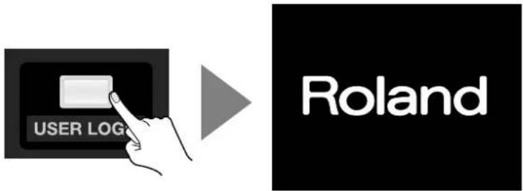
You can overwrite the default logo data in the VR-5 and output your own corporate or event logo.
1. Display the FILE UTILITY menu.
Press the [MAIN MENU] button to display the menu screen. Touch [FILE UTILITY] to display the FILE UTILITY menu screen.
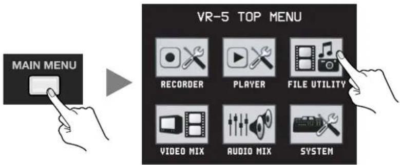
2. Select media containing a still image file.
Select the media that contains the still image file you want to use as the logo.
* When the still image file has been copied from an SD card to a USB memory device (p. 54), select [USB].
3. Select the still image file you want to use as the logo.
Selecting the still image file you want to use as the logo displays the UTILITY (PICTURE) dialog box.
4. Register the user logo.
Touching [USER LOGO] makes the display change to a confirmation screen. Touching [OK] registers the still image as the user logo, and the dialog box disappears. Touching [X] makes the dialog box disappear without registering.
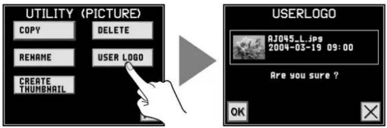
5. Go back to the original screen.
Press the [VIDEO PREVIEW] button to go back to the original four-way split screen.
Using the Features on the FILE UTILITY Menu
When you edit files or folders, use the FILE UTILITY menu.
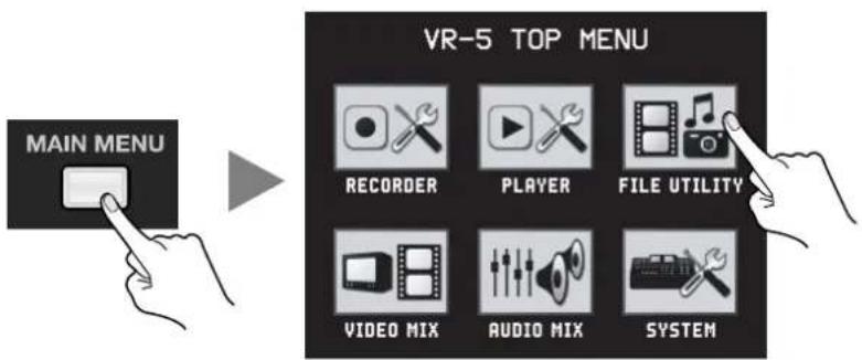
At the FILE UTILITY menu, you can use the following features.
• Copy /delete files or change file names
- Delete folders or change folder names
- Delete markers (movies only)
- Register thumbnails (movies only)
- Register a user logo (still image only) — Refer to "Registering a User Logo" (p. 53).
NOTE
At the FILE UTILITY menu, you can copy files from an SD card to a USB memory device, and carry out operations on the copied files. When connecting and using a USB memory device on the VR-5, give attention to the following points.
- Never make the connection through an extension cable or USB hub. Be sure to connect the VR-5 and the USB memory device directly.
- Open the sliding cover only when you're using the USB port. When this is not in use, be sure to keep the sliding cover closed to protect the connector inside.
- Operation has been tested for commonly available USB memory devices, but operation with all USB memory devices is not assured. Depending on the manufacturer and type of the USB memory devices, correct operation may not be possible.
* Connecting a USB memory device requires setting the USB mode. At the SYSTEM menu, select [VIDEO/AUDIO], then choose [USB MODE]. Set the mode to [STORAGE]. For information on the details of the SYSTEM menu, refer to "SYSTEM Menu" (p. 64).
Copying a File
1. Select the media.
Select the media that contains the file you want to copy.
* If you are copying an existing file from an SD card to a USB memory device, select [USB].
2. Select the file.
Selecting the file you want to copy displays a dialog box for editing operations.
3. Select [COPY].
In the dialog box, select [COPY].
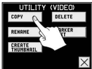
4. Select the copy destination.
Select the media to copy to. If you are copying from an SD card to a USB memory device, select [USB].
5. Select the copy-destination folder.
Select the folder to copy to. When you make the selection, [OK] appears at the lower left of the screen.
6. Perform the copy operation.
Touching [OK] at the lower left of the screen makes the display change to a confirmation dialog box. Touching [OK] in the dialog box copies the selected file. Touching [X] makes the dialog box disappear without copying anything.
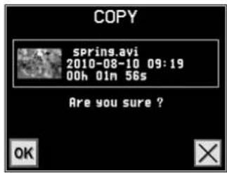
7. Go back to the original screen.
Press the [VIDEO PREVIEW] button to go back to the original four split screen.
Deleting a File
1. Select the media.
Select the media that contains the file you want to delete.
* If you are deleting a file copied from an SD card to a USB memory device, select [USB].
2. Select the file.
Selecting the file you want to delete displays a dialog box for selecting editing operations.
3. Select [DELETE].
Selecting [DELETE] makes the display change to a dialog box.
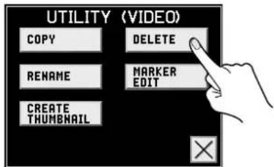
4. Delete the file.
Touching [OK] in the dialog box deletes the selected file. Touching [X] makes the dialog box disappear without deleting anything.
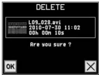
5. Go back to the original screen.
Press the [VIDEO PREVIEW] button to go back to the original four split screen.
Changing the Name of a File
The steps to select the file are the same as in "Deleting a File" (p. 55). Selecting [RENAME] as the editing operation makes the display change to a screen for changing the file name.
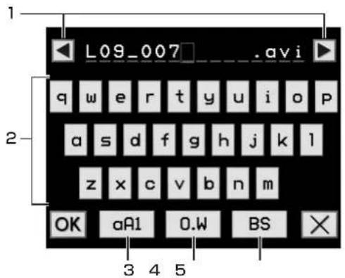
- Cursor These move the cursor to the left and right.
- Letters/numbers You use these to type in the file name.
- Caps This changes the mode for letters and numbers.
- Overwrite/insert This selects the input mode (overwrite or insert).
- Backspace This deletes entered characters.
Performing Operations on Folders
When you are deleting a folder or changing a folder name, press Folder Select (SEL), then select the target folder. A dialog box for selecting folder operations appears.
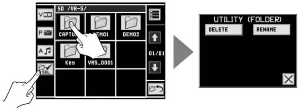
- [DELETE] This lets you delete the folder. The dialog box is the same as the one for deleting a file.
- [RENAME] This lets you change the folder name. The dialog box is the same as the one for changing a file name.
Editing Markers
For movie files only, you can select [MARKER EDIT] at the dialog box for selecting editing operations. Selecting [MARKER EDIT] makes the display change to the screen shown below, where you can carry out such tasks as deleting or repositioning markers added to a movie file.
* For information on how to add markers, refer to "Playback Using Markers" (p. 45).
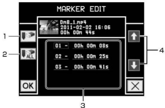
- Delete Marker This deletes only the marker selected in the marker number/location view.
- Delete All Markers This deletes all markers placed in the file.
- Marker number/location This displays the numbers and placed locations (hour/minute/second) of the markers.
- Up/down When the marker numbers are enclosed in a red box, these select the marker to edit.
When the location display is enclosed in a red box, you can use these to adjust the location.
Registering a Thumbnail for a Movie
For movie files only, you can select [CREATE THUMBNAIL] at the dialog box for selecting editing operations. Selecting [CREATE THUMBNAIL] makes the display change to the screen shown below, where you can move to the frame you wish to display as the thumbnail.
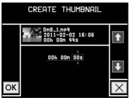
Returning to the Factory-default State
This returns various settings to their factory defaults. If following the instructions for a procedure results in operation that differs from what is described in the Owner's Manual, return the unit to its factory-default state.
NOTE
Restoring the factory-default state does not return the user logo to [Roland].
1. Display the menu.
Press the [MAIN MENU] button to access the menu screen.
2. Access the SYSTEM menu.
Touch [SYSTEM] to access the SYSTEM menu.
3. Return the unit to its factory-default state.
From [INITIALIZE], select [FACTORY RESET]. Touching [OK] at the confirmation screen returns the unit to its factory-default state.
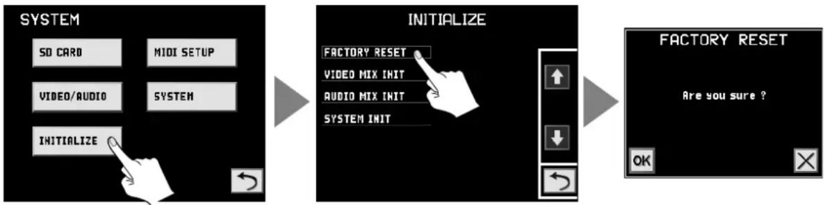
flowchart
graph LR
    A["SYSTEM"] --> B["Initialize"]
    B --> C["FACTORY RESET"]
    B --> D["VIDEO MIX INIT"]
    B --> E["AUDIO MIX INIT"]
    B --> F["SYSTEM INIT"]
    C --> G["FACTORY RESET"]
    D --> G
    E --> G
    F --> G
    G --> H["Are you sure ?"]
4. Go back to the original screen.
Press the [VIDEO PREVIEW] button to exit the menu screen.
Changing Between NTSC and PAL
NOTE
If the signals from connected external equipment differ from the setting on the VR-5, video may not be displayed correctly.
1. Display the menu.
Press the [MAIN MENU] button to access the menu screen.
2. Access the SYSTEM menu.
Touch [SYSTEM] to access the SYSTEM menu.
3. Switching Between NTSC and PAL
From [VIDEO/AUDIO], select [NTSC/PAL]. Use the [VALUE] knob to select [NTSC] or [PAL].
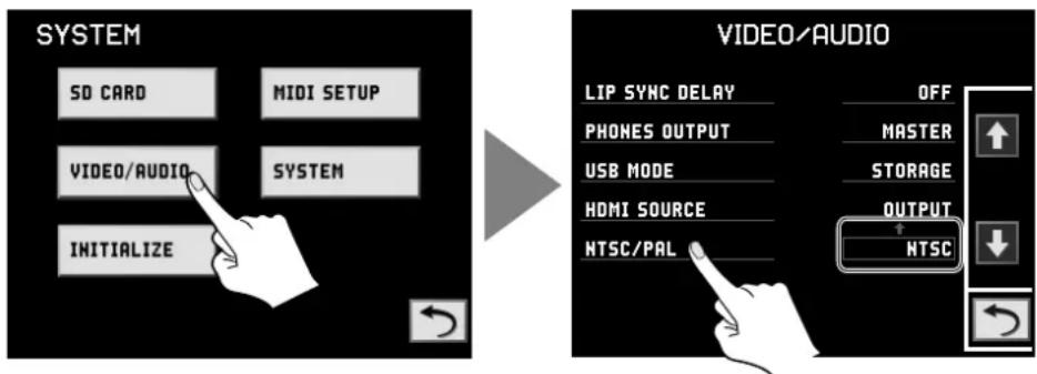
flowchart
graph LR
    A["SYSTEM"] --> B["SD CARD"]
    A --> C["MIDI SETUP"]
    A --> D["VIDEO/AUDIO"]
    A --> E["SYSTEM"]
    A --> F["INITIALIZE"]
    G["VIDEO/AUDIO"] --> H["LIP SYNC DELAY"]
    G --> I["OFF"]
    G --> J["PHONES OUTPUT"]
    G --> K["MASTER"]
    G --> L["USB MODE"]
    G --> M["STORAGE"]
    G --> N["HDMI SOURCE"]
    G --> O["OUTPUT"]
    G --> P["NTSC/PAL"]
    G --> Q["NTSC"]
4. Restart.
Switch off the power to the VR-5, then restart it. The unit starts up in the mode you selected in step 3.
Adjusting the Internal Calendar/Clock
The VR-5 has an internal calendar and clock. When recording is performed, the date and time from the calendar/clock are used as the file name. We recommend setting the calendar and clock to match the country or region of use.
* The date and time when the recording starts are used as the file name.
1. Display the menu.
Press the [MENU] button to access the menu screen.
2. Access the SYSTEM menu.
Touch [SYSTEM] to access the SYSTEM menu.
3. Display the calendar and clock.
From [SYSTEM], select [DATE & TIME]. The dialog box shown below appears.
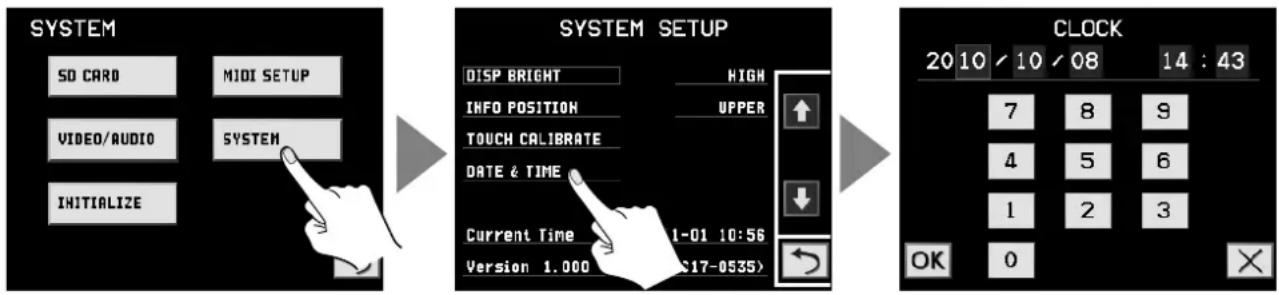
flowchart
graph LR
    A["SYSTEM"] --> B["SO CARD"]
    A --> C["MIDI SETUP"]
    A --> D["VIDEO/AUDIO"]
    A --> E["SYSTEM"]
    F["SYSTEM SETUP"] --> G["DISP BRIGHT"]
    F --> H["INFO POSITION"]
    F --> I["TOUCH CALIBRATE"]
    F --> J["DATE & TIME"]
    F --> K["Current Time 1-01 10:56"]
    F --> L["Version 1.000 (C17-0535)"]
    M["CLOCK"] --> N["20 10 10 08 14 : 43"]
    M --> O["7 8 9"]
    M --> P["4 5 6"]
    M --> Q["1 2 3"]
    M --> R["OK 0"]
4. Adjust the date and time.
Turning the [VALUE] dial moves the cursor. Touch the numbers below to adjust the date and time. After adjusting, touch [OK] to go back to the previous screen. Using [X] to return causes any changes to the date and time to be discarded.
5. Go back to the original screen.
Press the [VIDEO PREVIEW] button to exit the menu screen.
NOTE
If the power to this unit is not switched on for an extended period of time (about 6 months), the internal calendar and clock will be initialized. When initialized, set the date and time again with above steps.
Menu Operations
You can make various settings by using the buttons and dials in the [SETUP] section and by using the touch panel for the SETUP/PREVIEW MONITOR.
1. Display the menu.
Pressing the [MAIN MENU] button changes the SETUP/PREVIEW MONITOR from the four split screen to the menu display. Displayed first is the top menu screen. From here, you move to the screens for various items.
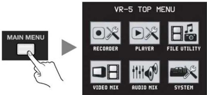
2. Choose the item whose setting you want to change.
Select the item whose setting you want to change by touching its icon on the touch panel.
* If the wrong item is selected, pressing the [EXIT] button returns the display to the previous screen.
* When the "Return" symbol is visible on the screen, touching it returns the display to the previous screen.
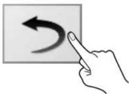
natural_image
Hand pointing at a curved arrow on a rectangular background (no text or symbols)3. Change the setting value.
Selecting an item and turning the [VALUE] dial changes the value.
* You can change a setting value up or down by 10 units at a time by pressing down the dial as you turn it.
* If a dialog box appears, touching [OK] applies the setting and exits the dialog box. Touching [X] exits the dialog box without applying the setting value.

4. Go back to the original screen.
Each press of the [EXIT] button makes the display go back one screen. If you want to go back to the four split screen for the video in a single step, press the [VIDEO PREVIEW] button.
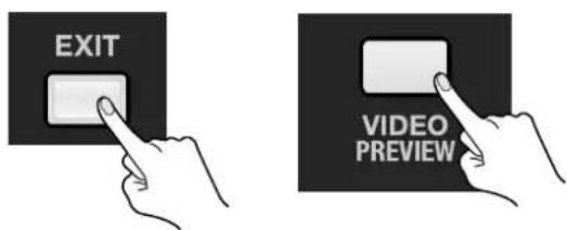
Menu List
RECORDER Menu
This is for making settings related to recording. At the initial [RECORDER FOLDER SELECT] screen, select the folder to contain the recording file.
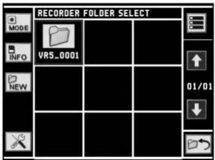
You can access dialog boxes and change screens by touching the items described below.
MODE
This accesses a dialog box for selecting the recording mode. For information on recording modes, refer to "Selecting a Recording Folder and Recording Mode" (p. 49).
INFO
This displays the remaining capacity of the SD card.

NEW
This accesses a dialog box for creating a new folder. When the message "Are you sure?" appears, touching [OK] creates a new folder.

Tool
This switches to the [THUMBNAIL TIME] screen. At this screen, you can select the location of the frame to display as the thumbnail. By default, the frame at 1 second from the beginning is displayed as the thumbnail. Use the [VALUE] dial to select the frame location.

MEMO
Operations performed by touching the icons on the right side of the screen (View Mode, Up/Down, and Return) are the same as at the file list screen. Refer to "FILE LIST Screen" (p. 43).
PLAYER Menu
This is for making settings related to playback. At the initial [PLAYER FILE SELECT] screen, select the file to play.
* Touching a folder icon displays a list of the files in the folder.
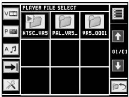
You can select files to play and change the playback mode by touching the items described below.
Video Select
This displays a list of only the movie files.

Picture Select
This displays a list of only the still image files.

Audio Select
This displays a list of only the audio files.

Playback Mode
This switches the playback mode. For information on the playback modes, refer to "Playback Modes" (p. 44).

flowchart
graph LR
    A["→"] --> B["←"]
    B --> C["→"]
    C --> D["←"]
Tool
This switches to the [PLAYER SETUP] screen. At this screen, you can select how playback starts.

You can select any of the following methods for starting playback.
- FILE SEL START Playback starts as soon as a file is selected.
• VIDEO SEL START Playback starts as soon as the [PLAYER] channel is selected.
MEMO
Operations performed by touching the icons on the right side of the screen (View Mode, Up/Down, and Return) are the same as at the file list screen. Refer to "FILE LIST Screen" (p. 43).
FILE UTILITY Menu
This is for carrying out operations such as deleting, copying, and renaming files. For information about the various features available on the FILE UTILITY menu, refer to "Using the Features on the FILE UTILITY Menu" (p. 54).
VIDEO MIX Menu
This is for settings related to switching, compositing, and inputting video.
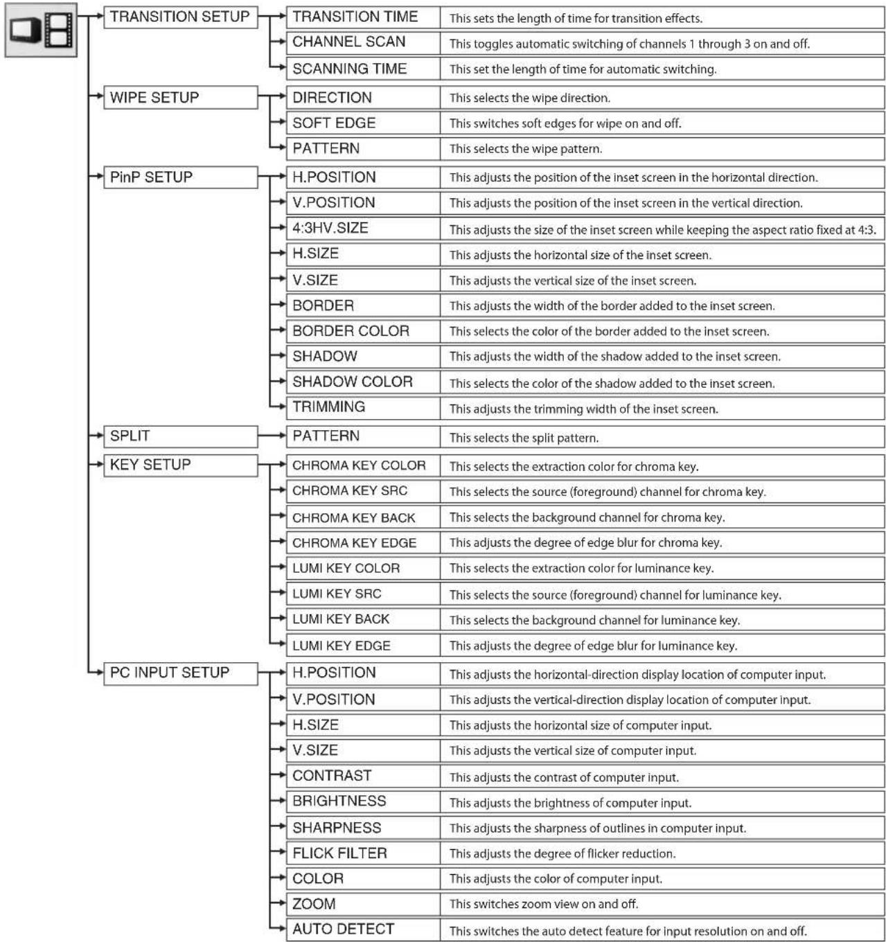
flowchart
graph TD
    A["Image"] --> B["TRANSITION SETUP"]
    A --> C["WIPE SETUP"]
    A --> D["PinP SETUP"]
    A --> E["SPLIT"]
    A --> F["KEY SETUP"]
    A --> G["PC INPUT SETUP"]

    B --> B1["TRANSITION TIME"]
    B --> B2["CHANNEL SCAN"]
    B --> B3["SCANNING TIME"]
    B --> B4["DIRECTION"]
    B --> B5["SOFT EDGE"]
    B --> B6["PATTERN"]
    B --> B7["H.POSITION"]
    B --> B8["V.POSITION"]
    B --> B9["4:3HV.SIZE"]
    B --> B10["H.SIZE"]
    B --> B11["V.SIZE"]
    B --> B12["BORDER"]
    B --> B13["BORDER COLOR"]
    B --> B14["SHADOW"]
    B --> B15["SHADOW COLOR"]
    B --> B16["TRIMMING"]
    B --> B17["PATTERN"]
    B --> B18["PATTERN"]
    B --> B19["CHROMA KEY COLOR"]
    B --> B20["CHROMA KEY SRC"]
    B --> B21["CHROMA KEY BACK"]
    B --> B22["CHROMA KEY EDGE"]
    B --> B23["LUMI KEY COLOR"]
    B --> B24["LUMI KEY SRC"]
    B --> B25["LUMI KEY BACK"]
    B --> B26["LUMI KEY EDGE"]
    B --> B27["H.POSITION"]
    B --> B28["V.POSITION"]
    B --> B29["H.SIZE"]
    B --> B30["V.SIZE"]
    B --> B31["CONTRAST"]
    B --> B32["BRIGHTNESS"]
    B --> B33["SHARPNESS"]
    B --> B34["FLICK FILTER"]
    B --> B35["COLOR"]
    B --> B36["ZOOM"]
    B --> B37["AUTO DETECT"]

    C --> C1["This sets the length of time for transition effects."]
    C --> C2["This toggles automatic switching of channels 1 through 3 on and off."]
    C --> C3["This set the length of time for automatic switching."]
    C --> C4["This selects the wipe direction."]
    C --> C5["This switches soft edges for wipe on and off."]
    C --> C6["This selects the wipe pattern."]
    C --> C7["This adjusts the position of the inset screen in the horizontal direction."]
    C --> C8["This adjusts the position of the inset screen in the vertical direction."]
    C --> C9["This adjusts the size of the inset screen while keeping the aspect ratio fixed at 4:3."]
    C --> C10["This adjusts the horizontal size of the inset screen."]
    C --> C11["This adjusts the vertical size of the inset screen."]
    C --> C12["This adjusts the width of the border added to the inset screen."]
    C --> C13["This selects the color of the border added to the inset screen."]
    C --> C14["This adjusts the width of the shadow added to the inset screen."]
    C --> C15["This selects the color of the shadow added to the inset screen."]
    C --> C16["This adjusts the trimming width of the inset screen."]
    C --> C17["PATTERN"]
    C --> C18["PATTERN"]
    C --> C19["PATTERN"]
    C --> C20["PATTERN"]
    C --> C21["PATTERN"]
    C --> C22["PATTERN"]
    C --> C23["PATTERN"]
    C --> C24["PATTERN"]
    C --> C25["PATTERN"]
    C --> C26["PATTERN"]
    C --> C27["PATTERN"]
    C --> C28["PATTERN"]
    C --> C29["PATTERN"]
    C --> C30["PATTERN"]
    C --> C31["PATTERN"]
    C --> C32["PATTERN"]
    C --> C33["PATTERN"]
    C --> C34["PATTERN"]
    C --> C35["PATTERN"]
    C --> C36["PATTERN"]
    C --> C37["PATTERN"]
    C --> C38["PATTERN"]
    C --> C39["PATTERN"]
AUDIO MIX Menu
This is for settings related to audio input/output and Audio Follow.
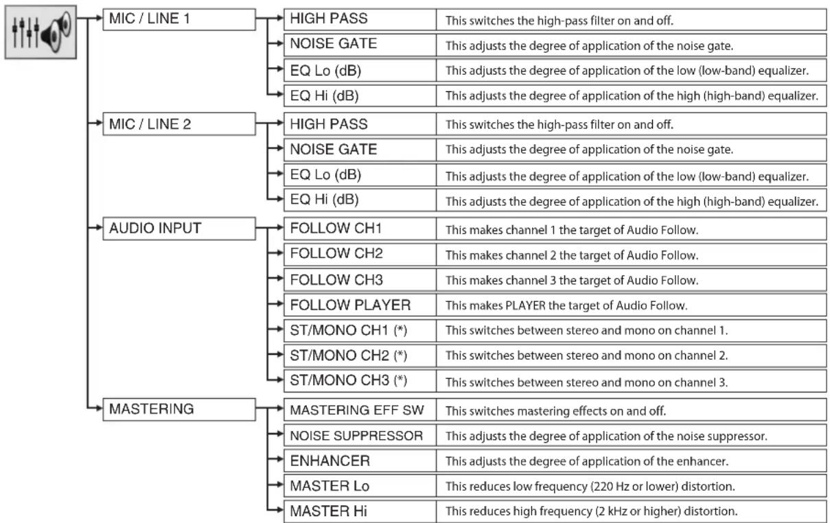
flowchart
graph TD
    A["MIC / LINE 1"] --> B["HIGH PASS"]
    A --> C["NOISE GATE"]
    A --> D["EQ Lo (dB)"]
    A --> E["EQ Hi (dB)"]
    A --> F["AUDIO INPUT"]
    F --> G["FOLLOW CH1"]
    F --> H["FOLLOW CH2"]
    F --> I["FOLLOW CH3"]
    F --> J["FOLLOW PLAYER"]
    F --> K["ST/MONO CH1 (*)"]
    F --> L["ST/MONO CH2 (*)"]
    F --> M["ST/MONO CH3 (*)"]
    F --> N["MASTERING EFF SW"]
    N --> O["NOISE SUPPRESSOR"]
    N --> P["ENHANCER"]
    N --> Q["MASTER Lo"]
    N --> R["MASTER Hi"]
    B --> S["This switches the high-pass filter on and off."]
    C --> T["This adjusts the degree of application of the noise gate."]
    D --> U["This adjusts the degree of application of the low (low-band) equalizer."]
    E --> V["This adjusts the degree of application of the high (high-band) equalizer."]
    G --> W["This makes channel 1 the target of Audio Follow."]
    H --> X["This makes channel 2 the target of Audio Follow."]
    I --> Y["This makes channel 3 the target of Audio Follow."]
    J --> Z["This makes PLAYER the target of Audio Follow."]
    K --> AA["This switches between stereo and mono on channel 1."]
    L --> AB["This switches between stereo and mono on channel 2."]
    M --> AC["This switches between stereo and mono on channel 3."]
    N --> AD["This switches mastering effects on and off."]
    O --> AE["This adjusts the degree of application of the noise suppressor."]
    P --> AF["This adjusts the degree of application of the enhancer."]
    Q --> AG["This reduces low frequency (220 Hz or lower) distortion."]
    R --> AH["This reduces high frequency (2 kHz or higher) distortion."]
* When the MONO setting is made, only the left-channel connectors are enabled. Right-channel connectors are disabled. The stereo position is centered.
SYSTEM Menu
This is for making various system settings for the VR-5.
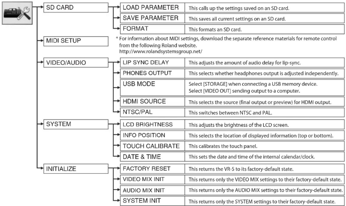
flowchart
graph TD
    A["User"] --> B["SD CARD"]
    A --> C["MIDI SETUP"]
    A --> D["VIDEO/AUDIO"]
    A --> E["SYSTEM"]
    A --> F["INITIALIZE"]

    B --> G["LOAD PARAMETER"]
    B --> H["SAVE PARAMETER"]
    B --> I["FORMAT"]
    G --> J["This calls up the settings saved on an SD card."]
    H --> K["This saves all current settings on an SD card."]
    I --> L["This formats an SD card."]

    C --> M["* For information about MIDI settings, download the separate reference materials for remote control from the following Roland website.<br>http://www.rolandsystemsgroup.net/"]

    D --> N["LIP SYNC DELAY"]
    D --> O["PHONES OUTPUT"]
    D --> P["USB MODE"]
    D --> Q["HDMI SOURCE"]
    D --> R["NTSC/PAL"]
    N --> S["This adjusts the amount of audio delay for lip-sync."]
    O --> T["This selects whether headphones output is adjusted independently."]
    P --> U["Select [STORAGE"] when connecting a USB memory device.
Select["VIDEO OUT"] sending output to a computer.]
    Q --> V["This selects the source (final output or preview) for HDMI output."]
    R --> W["This switches between NTSC and PAL."]

    E --> X["LCD BRIGHTNESS"]
    E --> Y["INFO POSITION"]
    E --> Z["TOUCH CALIBRATE"]
    E --> AA["DATE & TIME"]
    E --> AB["This adjusts the brightness of the LCD screen."]
    Y --> AC["This selects the location of displayed information (top or bottom)."]
    Z --> AD["This calibrates the touch panel."]
    AA --> AE["This sets the date and time of the internal calendar/clock."]

    F --> AF["FACTORY RESET"]
    F --> AG["VIDEO MIX INIT"]
    F --> AH["AUDIO MIX INIT"]
    F --> AI["SYSTEM INIT"]

    G --> J
    H --> J
    I --> J
    K --> J
    L --> J
    M --> J
    O --> J
    P --> J
    Q --> J
    R --> J
    S --> K
    T --> K
    U --> K
    V --> K
    W --> K
    X --> K
    Y --> K
    Z --> K
    AA --> K
    AB --> K
    AC --> K
    AD --> K
    AE --> K
    AF --> L
    AG --> L
    AH --> L
    AI --> L
Main Specifications
| Video Processing | Output Connectors | ||||
| Format | Video | NTSC/PAL (ITU601) | Video | Output | Composite (BNC type) x 2S-Video (4 pins mini DIN type) x 2 |
| PC-RGB | 640 x 480/120Hz, 800 x 600/120Hz,1024 x 768/80Hz,1152 x 864/75Hz,1280 x 1024/75Hz, 1600 x 1200/60Hz(RGB VH : Positive Logic/Negative Logic)* Conforms to VESA DMT Ver 1.0 Revision 10* The refresh rate is the maximum value of eachresolution. | Preview | Composite (BNC type) x 1 | ||
| Audio | Output | XLR type (balanced) x 1 pair (L/R)RCA pin type x 1 pair (L/R) | |||
| Phones | 1/4 inch phone type x 1 | ||||
| 480/60p, 576/50p (output only)HDMI | Video + Audio | HDMI TYPE A (19 pins) x 1 | |||
| Sampling | 13.5 MHz, 4:2:2 (Y:R-Y:B-Y), 8-bit | Other Connectors | |||
| Frame Synchronizer | Built-in x 5 | Remote Control | MIDI IN (5 pins DIN type) x 1MIDI OUT/THRU (5 pins DIN type) x 1 | ||
| Audio Processing | USB A type x 1 | * Supports USB 2.0 Hi-Speed | |||
| Sampling 24-bit/48 kHz | Effects | ||||
| Input Level and Impedance | Video | Transition | CUT, MIX,WIPE (hard edge/soft edge) | ||
| Video (Composite) | 1.0 Vp-p, 75 ohms | ||||
| S-Video | Luminance Signal : 1.0 Vp-p, 75 ohmsChrominance Signal : 0.286 Vp-p, 75 ohms (NTSC)0.3 Vp-p, 75 ohms (PAL) | Composition | Luminance Key, Chroma Key,Picture in Picture, Split | ||
| PC-RGB | 0.7 Vp-p, 75 ohms (H, V : 5VTTL) | Audio | MIC/LINE High-Pass, Noise Gate, EQ (Lo/Hi) | ||
| Output Mastering, Noise Suppressor, Enhancer | |||||
| Audio InputImpedance | MIC/LINE 1-2 (XLR) : 4 k ohmsMIC/LINE 1-2 (TRS) : 6 k ohmsCh 1 - 3, PC INPUT : 15 k ohms | Recording & Playback | |||
| Recording Media (*) | SD card (maximum 2 GB)SD-HC card (maximum 32 GB) | ||||
| Audio InputLevel | MIC/LINE | -68 to +4 dBu (variable)Maximum Input Level : +22 dBu | RecordingMethod | Format | .mp4 |
| -10 dBu, Maximum Input Level : +8 dBuCh 1 - 3 | VideoCodec | MPEG-4 Visual480/60i, 576/50i2 Mbps, 4 Mbps, 6 Mbps | |||
| -15 dBu, Maximum Input Level : +3 dBuPC INPUT | |||||
| Output Level and Impedance | AudioCodec | MPEG-1 Audio Layer 3 (MP3)48 kHz, 128 Kbps | |||
| Video (Composite) | 1.0 Vp-p, 75 ohms | File System (*) | FAT32 (maximum file size : 4 GB) | ||
| S-Video | Luminance Signal : 1.0 Vp-p, 75 ohmsChrominance Signal : 0.286 Vp-p, 75 ohms (NTSC)0.3 Vp-p, 75 ohms (PAL) | Recording Time(approx time of 4 GB rec) | 2 Mbps : approx 4 hours, 4 Mbps : approx 2 hours,6 Mbps : approx 80 minutes | ||
| Audio OutputImpedance | XLR : 600 ohmsRCA : 1 k ohmsPHONES : 10 ohms | SupportedPlaybackFormats | Video | .mp4, .avi 480/60i, 576/50i | |
| Picture | .bmp(maximum 2300 x 1725) jpg(maximum 3600 x 2700) | ||||
| Audio | .wav (16-bit/48kHz), .mp3 (48 kHz/128 Kbps) | ||||
| AudioOutput Level | -10 dBu, Maximum Output level : +8 dBuXLR/RCA | Others | |||
| 50 mW + 50 mWPHONES | |||||
| Input Connectors | DC 12V (AC adaptor)Power Supply | ||||
| Video | Composite (BNC type) x 3S-Video (4 pins mini DIN type) x 3* If simultaneously input, S-Video takes priority. | 3 ACurrent Draw | |||
| Dimensions | 376(W) x 308(D) x 133(H) mm14-13/16(W) x 12-1/8(D) x 5-1/4(H) inches | ||||
| PC-RGB | HD DB-15 type x 1 | Weight(excl. AC adaptor) | 4.3 kg9 lb 8 oz | ||
| Audio | MIC/LINE | XLR type (balanced, phantom power) x 2TRS type (balanced/unbalanced) x 2* If simultaneously input, TRS takes priority. | Accessories | AC adaptor with power cord,RCA - BNC conversion plug x 4,USB cable (A type - A type) x 1,SD card (incl. video/picture/audio contents),Owner's Manual | |
| Ch 1 - 3 | RCA pin type x 3 pairs (L/R) | ||||
| PC INPUT | Stereo mini type x 1 | ||||
* Only SD cards of class 4 or higher can be used for recording or playback on the VR-5. Be sure to use SD cards of class 4 or higher.
* Continuous recording is possible until a recording file size reaches 4 GB. When the file size reaches 4 GB, recording automatically stops. If recording is restarted after an automatic stop, the data is saved on the SD card as a separate file.
* In the interest of product improvement, the specifications and/or appearance of this unit are subject to change without prior notice.
NOTE
This unit is a Class A device under FCC Part 15.
Remote Control
The VR-5 can be operated remotely from an external V-LINK or MIDI device. For more information about remote control, download the separately available reference document from the following Roland website.
http://www.rolandsystemsgroup.net/
Error Messages
If a processing error occurs, an error message like below appears on the OUTPUT MONITOR.
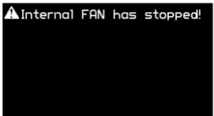
If an error message appears, take corrective action as described below.
SD Card not found!
No SD card is inserted. Switch off the power to the VR-5, then insert an SD card.
SD Card is ejected!
The SD card was removed during recording or playback. Switch off the power to the VR-5, then reinsert the SD card.
Format SD Card!
The SD card is not one that has been formatted for the VR-5. Format the SD card.
This SD Card is locked!
The SD card is locked. Switch off the power to the VR-5, unlock the SD card, then reinsert it.
SD Card is full!
The SD card has no free space remaining. Switch off the power to the VR-5, then replace the SD card with a different one.
Select recording folder!
No folder for saving the recorded file has been selected. Select a folder.
Select play file!
No File to play back has been selected. Select a file.
Improper file type!
A file not supported by the VR-5 was selected. Select a supported file.
No User Logo!
The user logo data has been erased. Register a user logo again.
Clock Initialized!
The internal calendar/clock was initialized because the power supply has been stopped for a long time. Set the date and time again.
Internal FAN has stopped!
The ventilation fan has stopped. Stop use immediately, and contact your nearest Roland Service Center.
SD Card folder not found!
The playback/recording folder on the SD card was not found. Select the playback/recording folder again.
Now Recording!
Recording is in progress. Temporarily stop recording, then carry out the operation.
Do Not Eject the SD Card!
The SD card is being accessed. Do not remove the SD card.
Troubleshooting
The power is not switched off.
Was the [POWER] button pressed after too long of a pause?
The power is not switched off unless the [POWER] button is pressed within 5 seconds after the "Press POWER Again!" message appears.
No picture is output to the projector.
Is the [VIDEO OUT] dial centered?
A fade is applied to output if the dial is turned either clockwise or counterclockwise. When performing output, adjust the dial to center. The indicator above the dial lights up when the dial is at center. The indicator flashes when the dial has been turned either clockwise or counterclockwise.
No microphone audio is output, even when the faders are raised.
Have the [GAIN] dials been turned to appropriate positions?
When input sensitivity has been lowered, no audio is output even when the faders are raised.
Is the connected microphone a condenser mic?
When you're connecting a condenser microphone or other device that requires phantom power, set the [PHANTOM +48V] switch to ON.
Input from an external audio mixer is distorted.
Does the device have a high nominal output level?
The VR-5 has a nominal input level of -10 dBu. When you are connecting a equipment that has a high output level, such as +4 dBu, connect it via an attenuator.
Transition effects are not applied.
Is the length of time for transition effects (TRANSITION TIME) set at zero?
When the time is set at zero, no transition effects are applied even when [MIX] or [WIPE] is selected.
A logo cannot be input from a computer.
Is the RGB output from the computer at a resolution supported by the VR-5?
RGB signals at a resolution that the VR-5 does not support cannot be input correctly. For supported resolutions, check "Main Specifications" (p. 65).
Video from the computer is not smooth.
This does not indicate an equipment malfunction. When quickly moving image is input from computer, flicker or other image corruption may occur. This is called "tearing".
Compositing a logo is not possible.
Is the extraction color set correctly? Alternatively, was the [KEY LEVEL] dial turned in the wrong direction?
When the default settings are in effect, black is extracted to luminance keying and blue is extracted for chroma keying. If the background is a different color, then correct extraction is not possible. Correct extraction is also impossible when the [KEY LEVEL] dial has been turned in the wrong direction.
Audio is not linked to video transitions.
Is the channel of the audio you want to link not selected as the target for linking?
On channels that are not set as the target, no automatic switching of output and muting takes place when the video is switched. Use the menus to make these the target of linking (p. 64).
Picture-in-Picture compositing is not possible.
Is the [MODE] button in the video effects section dark?
When this button is illuminated, the compositing mode is set to SPLIT.
Recording and playback using a commercially available SD card are not possible.
Operation has been tested for many common commercially available SD cards, but operation with all SD cards is not assured. Depending on the manufacturer and type of the SD card, correct recording and playback may not be possible. Try replacing with a different SD card.
Also, only cards of class 4 or higher can be used for recording or playback on the VR-5. Be sure to use cards of class 4 or higher.
SDXC cards cannot be used.
The VR-5 is compatible with SD cards and SDHC (High Capacity) cards, but does not support SDXC (eXtended Capacity) cards. Use an SD card or SDHC card.
Flicker occurs on a flat-screen monitor.
Flicker can occur, depending on the displayed picture, but this is not a malfunction.
Recording/playback using a commercially available SD card is not possible.
When an SD card is in the write-protected (LOCK) state, data on the SD card cannot be recorded, played back, or manipulated by FILE UTILITY or the like. When using an SD card on the VR-5, first clear the write protection (LOCK).
Artist Profiles
The content on the included SD card was created by the following artists.
* The copyright of contents in accessory SD card (movie data, picture data and sound waveform data) of this product is reserved by Roland Corporation.
Purchasers of this product are permitted to utilize said content for the creating, performing, recording and distributing original visual or musical works. Commercial use is also possible. Purchasers of this product are NOT permitted to extract said content in original or modified form, for the purposes of distributing recorded medium of said content or making them available on a computer network.
Masaru Ozaki (VJ MASARU)
Filmmaker, Ambient Video Producer, and Art Director
As Japan's foremost projection-mapping artist and video producer, Masaru is a performing art pioneer who creates images in real time to music at stage performances and live events. As a VJ, in 2005 he released the "BEHIND" DVD featuring a performance in which he made the world's first use of a novel crossfader technique.
Masaru is also engaged in visual and ambient production for fashion shows by John Lawrence Sullivan, Neil Barrett, Diesel, and other leading global brands. At Japan Fashion Week in Tokyo, he created a real-time scan of a three-dimensional object over 30 meters high.
His artistic piece "chair" is a "sculpture of light" created by projecting a 3D image onto a solid object. At "Rooms," the largest fashion event of its kind in Japan or abroad, held in February 2009, he conducted a projection-mapping performance that involved scanning the Yoyogi
natural_image
Black-and-white portrait of a bald man with short hair, wearing a dark top (no text or symbols visible)National Gymnasium, adjusting the image, and projecting it as a 3D visual. Later that year, he was commissioned to create a Christmas tree installation in commemoration of the 40th anniversary of the Japan's Parco department store, and a one-man exhibition titled "Masaru Ozaki: Motion + Design + Magic" was held concurrently. A solo show at Parco Factory in Fukuoka, Japan in 2010 drew 53,072 visitors over its two-week run, earning the artist wide attention as a ground-breaking auteur of visuals and sculpture.
Masaru is also expanding his activities world wide, and had a hand in many installations at the Expo 2010 Shanghai China that began in May 2010, including a piece on permanent display at the main entrance to the Japan Pavilion.
He has produced or created performance images for concerts for Hideaki Tokunaga, Hound Dog, the Ungirls comedy duo, Fashion Week Japan in Tokyo, and classical music concerts emceed by Akira Senju, and has performed at numerous club events. He has created promotional videos for Gravity and Yellow Generation, and has created numerous title background animations for TV shows such as Universal Studios Japan "KWBB," Denki Groove "WIRE.WIRELESS" TV SPOT, and the "Daisuki!" drama series.
Masaru also designs graphics for advertisements and flyers, consults on product design for Roland and other firms, and assists brand art direction for companies such as Goldwin.
Tosh Masuda
Since graduating from the Showa Academia Musicae Composition Department's Digital Music course, Tosh Masuda has appeared as an arranger, sound producer, composer, programmer, and musician.
As a sound producer, Tosh has worked with such Japanese artists as ACO, Keyco, SAKURA, HOME MADE KAZOKU, CORE OF SOUL, and SKOOP ON SOMEBODY. He has made arrangements for Chemistry, RHYTHEM, and Miho Nakayama and worked as a mixer for Ayumi Hamasaki and MIHO.
Tosh is a multi-instrumentalist musician, doing his own programming and performing on guitar and bass. With the Japanese group CALM, Tosh has also shown his skill on multiple recordings, at concerts, and singing for television commercials.
Applying his talents to an even wider array of activities, Tosh worked with Masaru Ozaki on the music for the Japan Pavilion at Expo 2010 Shanghai China and for department store Parco's 40th

natural_image
Portrait of a man wearing glasses and a cap with 'GL' (no text or symbols visible)anniversary Christmas tree, and has gone to work as a sound producer for live events by the Japanese comedy duo Ninety-Nine. Tosh has been the musical director and singing instructor for stage productions by well-known Japanese screenwriter Kankuro Kudo, as well as the arranger for stage productions by Suzuki Matsuo, and is also active as a member of Lime Sour, the hip-hop unit of the Japanese band Group Tamashii.
A
Amplifier 27
AUDIO FOLLOW 17,31
Audio Mixer 26
Audio Mixer Section 12
C
calendar 59
clock 59
condenser microphone 25
Cord Hook 10
D
dynamic microphone 25
E
ENTER 13
EXIT 13
F
FACTORY RESET 58
fade-in 33
fade-out 33
FILE LIST 43
File Select Section 12
FILE UTILITY 54
FORMAT 48
G
GAIN 16
H
HDMI 20,27
|
INFO 14
K
KEY LEVEL 18
KEY ON 18
L
LEVEL 15
LIP SYNC DELAY 31
logo 38
M
MAIN MENU 13
Marker 19
Menu 60
MIC/LINE 16
Microphones 25
MIDI 20
N
NTSC 58
0
Operating Systems 51
OUTPUT MONITOR 13
Output Section 12
P
PAL 58
PAN 16
PC INPUT Section 12
PC SELECT 18
PHONES 21
Picture-in-Picture 34
PinP 34
Playback Modes 44
PREVIEW 27
Projector 26
R
Recorder Section 12
RGB 24
S
Search Buttons 44
Search/Slow 19
SETUP 60
Setup/Display Section 12
SETUP/PREVIEW MONITOR 13
SIG/PEAK 16
slow 46
Split 36
SUB VIDEO SELECT 17,35
T
Touch Panel 28
TRANSITION 17,28
U
USB 51
USB Port 15
USER LOGO 14,53
V
VALUE 13
VIDEO OUT 15
Video Select Section 12
View Mode 13
V-LINK 13
For the USA
FEDERAL COMMUNICATIONS COMMISSION RADIO FREQUENCY INTERFERENCE STATEMENT
This equipment has been tested and found to comply with the limits for a Class A digital device, pursuant to Part 15 of the FCC Rules. These limits are designed to provide reasonable protection against harmful interference when the equipment is operated in a commercial environment. This equipment generates, uses, and can radiate radio frequency energy and, if not installed and used in accordance with the instruction manual, may cause harmful interference to radio communications. Operation of this equipment in a residential area is likely to cause harmful interference in which case the user will be required to correct the interference at his own expense.
This device complies with Part 15 of the FCC Rules. Operation is subject to the following two conditions:
(1) this device may not cause harmful interference, and
(2) this device must accept any interference received, including interference that may cause undesired operation.
To assure continued FCC emission limit compliance, use only shielded interface cables when connecting to other device. Any unauthorized changes or modifications not expressly approved by the party responsible for compliance could void the user's authority to operate the equipment.
For Canada
NOTICE
This Class A digital apparatus meets all requirements of the Canadian Interference-Causing Equipment Regulations.
AVIS
This product contains chemicals known to cause cancer, birth defects and other reproductive harm, including lead.
For China
有关产品中所含有害物质的说明
This symbol indicates that in EU countries, this product must be collected separately from household waste, as defined in each region. Products bearing this symbol must not be discarded together with household waste.
This product is intended for use in the following Electromagnetic environments:
E1: residential, E2: commercial and light industrial, E3: urban outdoors,
ex. recording studio (broadcasting studio) which are specified in EN55103-1 and EN55103-2.
- INSTRUCTIONS FOR THE PREVENTION OF FIRE, ELECTRIC SHOCK, OR INJURY TO PERSONS
- ALWAYS OBSERVE THE FOLLOWING
- WARNING
- CAUTION
- Power Supply
- Placement
- Maintenance
- Additional Precautions
- Before Using SD Cards
- Copyright
- About Intellectual Property Rights
- Others
- Turning the Power On/Off.... 10
- Names of Things and What They Do 12
- Connecting External Equipment 23
- Basic Operation.... 28
- Compositing the Video 34
- Performing Playback from an SD Card 40
- Recording to an SD card.... 47
- Performing Output from the USB Port....51
- Registering a User Logo 53
- Other Features 54
- Menu Operations and Menu List 60
- Appendices....65
- Connecting the AC adaptor
- About Cord Hook
- Caution regarding the power supply
- Turning the power on
- Turning the power off
- NOTE
- Top Panel
- Setup/Display Section (p. 13)
- Output Section (p. 15)
- Audio Mixer Section (p. 16)
- Video Select Section (p. 17)
- Video Effects Section (p. 17)
- PC INPUT Section (p. 18)
- Recorder Section (p. 19)
- File Select Section (p. 19)
- Setup/Display Section
- V-LINK Indicator
- MEMO
- SETUP/PREVIEW MONITOR
- OUTPUT MONITOR
- MAIN MENU Button (p. 60)
- EXIT Button
- ENTER Button
- VALUE Dial
- View Mode Buttons
- INFO Button
- USER LOGO Button (p. 53)
- Output Section
- USB Port (p. 51)
- POWER Button (p. 11)
- VIDEO OUT Dial (p. 33)
- LEVEL Indicator
- AUDIO OUT LEVEL Dial (p. 33)
- Audio Mixer Section
- GAIN Dial and SIG/PEAK Indicator for MIC/LINE 1
- PAN Switch for MIC/LINE 1
- GAIN Dial and SIG/PEAK Indicator for MIC/LINE 2
- PAN Switch for MIC/LINE 2
- MIC/LINE 1/2 Faders
- 1 - 3 Faders
- PLAYER Fader
- Video Select Section
- Video Effects Section
- AUDIO FOLLOW Button (p. 31)
- SUB VIDEO SELECT Buttons (p. 34, p. 36)
- MODE Button (p. 34, p. 36)
- TRANSITION Buttons (p. 28)
- PC INPUT Section
- PC AUDIO LEVEL Dial
- KEY LEVEL Dial (p. 39)
- KEY ON Button (p. 38)
- PC SELECT Button (p. 39)
- Recorder Section
- Marker Buttons (p. 45)
- Search/Slow Buttons (p. 44, p. 46)
- Record/Playback Control Buttons (p. 50)
- File Select Section
- Rear Panel
- DC IN Jack (p. 10)
- AUDIO OUTPUT Connectors
- VIDEO OUTPUT Connectors
- PREVIEW OUT Connector
- VIDEO INPUT Connectors
- MIC/LINE INPUT Connectors
- MIDI IN and OUT/THRU Connectors
- HDMI OUT Connector
- PC INPUT Connectors
- AUDIO INPUT Connectors
- Front Panel
- PHONES Jack and LEVEL Dial
- SD CARD Slot
- Signal Flow
- Connecting Source Equipment
- Connecting Video Equipment
- Connect a computer.
- Connecting Audio Equipment
- Connecting Playback Equipment
- Connecting Microphones
- Connecting an External Audio Mixer
- Connecting Output Equipment
- Connecting a Projector or Recorder
- Connecting an Amplifier/Speakers or Recorder
- Connecting a Monitor Display
- HDMI OUT Connector
- PREVIEW OUT Connector
- Switching the Video
- Using the Touch Panel to Switch the Video
- Display the input from the source.
- Select a transition effect.
- Select a different channel.
- Using Button Operations to Switch the Video
- Adjusting the Volume Balance
- Lower all faders completely.
- Raise the volume level of each channel.
- Adjust the volume balance for the channels.
- Linking Audio to Video
- Adjust the audio on the respective channels.
- Switch on the link feature.
- Switch the video channel.
- Applying Effects to Audio
- For MIC/LINE 1 and 2
- For Final Output
- Display the AUDIO MIX menu.
- Select the target channel.
- Select the effect to apply.
- Switch the effect on or off, or adjust it.
- Go back to the original screen.
- Applying a Fade to Final Video Output
- Fade Out
- Fade In
- Adjusting the Volume of the Final Output
- Check the volume level of the final output.
- Adjust the volume level.
- Two-screen Composition Using Picture-in-Picture
- Select the PinP mode.
- Select the background.
- Select the channel for the inset screen.
- Make the inset screen disappear.
- Adjusting the Position and Size of the Inset Screen
- Two-screen Composition Using Split
- Select the SPLIT mode.
- Select the channel to display on A-side.
- Select the channel to display on B-side.
- Quitting the split view.
- Compositing a Logo or Text from a Computer
- Create the background.
- Switch on the key-compositing feature.
- Adjust the degree of extraction.
- Make the logo or text disappear.
- Display the Images from Computer Only
- Performing Playback from an SD Card
- Inserting an SD Card into the Slot
- About the contents included in accessory SD Card
- SD Card Folder Structure
- Supported File Formats for Playback
- About Write-protect (LOCK) Feature
- File Playback
- Select the type of file to play.
- Select the file to play back.
- Quit the menu screen.
- Output the played video or audio.
- Stop or pause playback.
- FILE LIST Screen
- File Type Selectors
- Playback Mode Switch
- Tool
- View Mode
- Up/Down
- Return
- Playback Modes
- Search Buttons
- Useful Playback Features
- Playback Using Markers
- Place markers in the file.
- TIP
- Jump to a marker location.
- Delete a marker.
- SLOW Playback
- Perform playback.
- Perform slow playback.
- Change the speed of slow playback.
- Return to normal playback.
- About SD card
- About Recording Time
- About File Names of the Recorded Data
- Formatting an SD card
- Insert the SD card
- Open SYSTEM menu
- Select [FORMAT]
- Execute format
- Go back to the original screen
- Selecting a Recording Folder and Recording Mode
- Open RECORDER menu
- Select a recording folder
- Open REC MODE menu and select recording mode
- Go back to the original screen
- Record the Final Output
- Output the video and audio to record
- Standby the recording
- Start recording
- Pause recording
- Stop recording
- Supported Operating Systems
- Check the USB mode of the VR-5.
- Connect a computer.
- Wait for communication between the VR-5 and the computer to be established.
- Make sure the VR-5 is detected.
- Performing Output to a Computer
- Enable a state allowing output of video or audio.
- On the computer, verify the input from the VR-5.
- Output Signals
- Cautions on Streaming
- Display the FILE UTILITY menu.
- Select media containing a still image file.
- Select the still image file you want to use as the logo.
- Register the user logo.
- Using the Features on the FILE UTILITY Menu
- Copying a File
- Select the media.
- Select the file.
- Select [COPY].
- Select the copy destination.
- Select the copy-destination folder.
- Perform the copy operation.
- Go back to the original screen.
- Deleting a File
- Select [DELETE].
- Delete the file.
- Changing the Name of a File
- Performing Operations on Folders
- Editing Markers
- Registering a Thumbnail for a Movie
- Returning to the Factory-default State
- Display the menu.
- Access the SYSTEM menu.
- Return the unit to its factory-default state.
- Go back to the original screen.
- Changing Between NTSC and PAL
- Switching Between NTSC and PAL
- Restart.
- Adjusting the Internal Calendar/Clock
- Display the calendar and clock.
- Adjust the date and time.
- Menu Operations
- Choose the item whose setting you want to change.
- Change the setting value.
- Menu List
- RECORDER Menu
- MODE
- INFO
- NEW
- Tool
- PLAYER Menu
- Video Select
- Picture Select
- Audio Select
- Playback Mode
- FILE UTILITY Menu
- VIDEO MIX Menu
- AUDIO MIX Menu
- SYSTEM Menu
- Remote Control
- Error Messages
- SD Card not found!
- SD Card is ejected!
- Format SD Card!
- This SD Card is locked!
- SD Card is full!
- Select recording folder!
- Select play file!
- Improper file type!
- No User Logo!
- Clock Initialized!
- Internal FAN has stopped!
- SD Card folder not found!
- Now Recording!
- Do Not Eject the SD Card!
- Troubleshooting
- The power is not switched off.
- No picture is output to the projector.
- No microphone audio is output, even when the faders are raised.
- Input from an external audio mixer is distorted.
- Transition effects are not applied.
- A logo cannot be input from a computer.
- Video from the computer is not smooth.
- Compositing a logo is not possible.
- Audio is not linked to video transitions.
- Picture-in-Picture compositing is not possible.
- Recording and playback using a commercially available SD card are not possible.
- SDXC cards cannot be used.
- Flicker occurs on a flat-screen monitor.
- Recording/playback using a commercially available SD card is not possible.
- Artist Profiles
- Masaru Ozaki (VJ MASARU)
- Tosh Masuda
- A
- C
- D
- E
- F
- G
- H
- |
- K
- L
- M
- N
- 0
- P
- R
- S
- T
- U
- V
- FEDERAL COMMUNICATIONS COMMISSION RADIO FREQUENCY INTERFERENCE STATEMENT
- NOTICE
- AVIS
- 有关产品中所含有害物质的说明
Brand : ROLAND
Model : VR-5
Category : Blender