
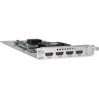
OEC 40 micro - Antenna KATHREIN - Free user manual and instructions
Find the device manual for free OEC 40 micro KATHREIN in PDF.


| Product Type | Indoor TV Antenna |
| Brand | Kathrein |
| Model | OEC 40 micro |
| Frequency Range | 174-230 MHz (VHF) / 470-862 MHz (UHF) |
| Gain | Typ. 15 dBi (UHF) |
| Polarization | Horizontal / Vertical |
| Impedance | 75 Ω |
| Dimensions (W x H x D) | 120 x 80 x 30 mm |
| Weight | 0.2 kg |
| Power Supply | 5 V DC via coaxial cable (active antenna) |
| Connector | F-type female |
| Mounting Type | Magnetic base or adhesive pad |
| Color | Black |
| Operating Temperature | -20°C to +60°C |
| Main Functions | Receives DVB-T/T2 digital terrestrial TV signals |
| Special Features | Integrated low-noise amplifier, compact design |
| Care and Cleaning | Wipe with a dry cloth; avoid water ingress |
| Safety | Do not install near overhead power lines |
| Spare Parts and Repairability | No user-serviceable parts; contact Kathrein support |
| General Information | Designed for indoor or window mounting |
Frequently Asked Questions - OEC 40 micro KATHREIN
User questions about OEC 40 micro KATHREIN
0 question about this device. Answer the ones you know or ask your own.
Ask a new question about this device
Download the instructions for your Antenna in PDF format for free! Find your manual OEC 40 micro - KATHREIN and take your electronic device back in hand. On this page are published all the documents necessary for the use of your device. OEC 40 micro by KATHREIN.
USER MANUAL OEC 40 micro KATHREIN
OSC 100 micro 205500005
OEC 40 micro 205500002
OEC 44 micro 205500003
Optical Sat Distribution
Optical Transmitter
Optical Distribution Receivers

KATHREIN
Digital Systems GmbH
Features optical transmitter OSC 100 micro
■ Premium optical CLIK! connector
■ Use standard universal quatro LNB (UAS 584) to feed in signals to the transmitter (OSC 100 micro).
■ Easy system planning using the "CLIKulator".
Address: http://clikulator.com/kathrein
■ Transmission of the entire digital terrestrial frequency range
■ AGC (no adjustment required)
■ Optical budget up to 21 dB
■ For indoor installation
Features optical distribution receivers OEC 40 micro/OEC 44 micro
■ Premium optical CLIK! connector
■ Easy system planning using the "CLIKulator": http://clikulator.com/kathrein
■ Transmission of the entire digital terrestrial frequency range
■ For indoor installation
Variants
■ OEC 40 micro - Optical receiver quatro (fixed outputs for multi-switch operation)
■ OEC 44 micro - Optical receiver quad (switchable outputs for direct connection of receiver)
Product description
The optical transmitter (OSC 100 micro) and the optical receiver (OEC 40 micro and OEC 44 micro) can be used to distribute satellite and digital terrestrial signals (FM/DAB+/digital TV) through a single-mode fibre optic cable.
The RF signal fed into the OSC 100 micro is converted into an optical signal. This optical signal is fed through the fibre optic cable to an optical network (tap/splitter/attenuator) and thus finds the optical receiver OEC 40 micro/OEC 44 micro. The receivers will then convert the received optical signal back into an RF signal.
The transmitter (OSC 100 micro) is equipped with loop-through outputs. Several transmitters are cascaded.
The optical transmitter is also equipped with AGC (Automatic Gain Control) providing for an automatically controlled optical output level. Therefore, no adjustment is required on the transmitter.
The receiver (OEC 40 micro) converts the incoming optical signal into the four outputs with fixed satellite polarisation planes and an output for digital terrestrial signals thus allowing direct connection of a multi-switch on the outputs.
The receiver OEC 44 micro converts the incoming optical signal into the four switchable universal outputs thus allowing the digital terrestrial and the satellite signal to be made available for four different receivers or TV sets.
Installation and safety instructions

- The equipment described is designed solely for installation in satellite receiver systems. Any other use or failure to comply with these instructions will void the warranty or guarantee.
- The equipment may only be installed in dry areas indoors. Do not install on or against highly combustible materials, near or over heat sources or in contact with/near corrosive substances.
- The units must be connected to the equipotential bonding rail (Cu, at least 4 mm ^2 ).
- The unit must be installed by qualified personnel in compliance with the local security standards and regulations. The unit complies to protection class II and thus need not be connected to the protective earthing of the mains supply.
- The safety regulations set out in the current EN 60728-11 and EN 62368-1 standards must be complied with.
- The units are intended for on-wall installation only. Do not install the device lying flat or on its top, or operate it in this position.
• RF connectors 75 Ω (F series) compliant with EN 61169-24.
• Optical connectors: CLIK!
• Unused optical outputs are to be terminated with OTC 1. - Unused coaxial connectors are to be terminated with EMK 03, with the exception of the 4 SAT inputs of OSC 100 micro, which due to DC voltage must be terminated with EMK 05.
- Do not place any liquid-filled items or items with naked flames (e.g. candles) on top of the unit.
- There must be free circulation of air to discharge the heat emitted by the unit. Danger of overheating! Clearance all around at least 5 cm!
• Permissible ambient temperature: +5 to +45°C
Mounting
Transmitter (OSC 100 micro) and receiver (OEC 40 micro or OEC 44 micro) can be mounted using 4 wood screws, self-tapping screws or plug screws (thread diameter 4.5 ... 5 mm; head diameter ≥ 9 mm; screw length ≥ 20 mm; round or cylinder head). The screws required for mounting are not included.


natural_image
Pure electrical circuit lines without any symbols
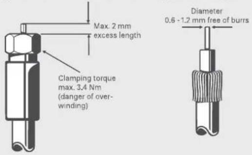
Risk of material damage to the device!
If the inner cable conductor diameter is more than 1.2 mm, or if burring is present, the device sockets may be destroyed.

Equipotential bonding terminal
The devices must be connected to the equipotential bonding of the antenna installation as per EN 60728-11.

Current-carrying device
- The supply voltage of the units (OSC 100 micro and OEC 44 micro) is 220-240 V _AC which can be fatal if touched directly.
- When working on the system, always unplug the mains plug from the wall socket!
- The units may only be installed and deinstalled in the voltage-free condition.
- Only use the supplied power cable (adapter). The mains plug must be easily accessible and operable.
- The only reliable method of disconnecting the unit from the mains is to unplug it.
- Do not place any liquid-filled items on top of the power supply unit.
- The power supply unit must not be exposed to dripping or splashing water.
- Humidity and condensation may damage the unit. In case of condensation, wait until the device is dry prior to operation.
- When performing work on the optical distribution network, make sure that the lasers of the connected transmitter have been switched off by disconnecting the mains plug.
- Do not open the unit or tamper with it! Under no circumstances should you look inside the optical connectors either with the naked eye and/or optical instruments! This can prove seriously harmful to your health. Laser radiation is invisible to the human eye.
- This unit may be only be operated by personnel who have received the necessary training in handling optical and electrical devices and have been instructed in the safety rules for handling lasers.
SIMPLIFIED EU DECLARATION OF CONFORMITY
Hereby, KATHREIN Digital Systems GmbH declares that the radio equipment types
OEC 40 micro, order no.: 205500002,
OEC 44 micro, order no.: 205500003 and
OSC 100 micro, order no.: 205500005
are in compliance with Directive 2014/53/EU. The full text of the EU declaration of conformity is available at the following internet address: www.kathrein-ds.com
Connections optical transmitter OSC 100 micro

| 1 | Equipotential bonding terminal: | ± Equipotential bonding (as per EN 60728-11) |
| 2 SAT inputs: | F-type connectors for the four Sat-IF polarities (950-2,150 MHz) with LNB remote feeding | |
| 3 | Terrestrial input: | F-type connector for FM/DAB+/digital TV signals (87.5-862 MHz) |
| 4 Test output SAT: | F-type connector for the SAT test signal, HH polarity (RF level: 60 dBμV per transponder). | |
| 5 Test output TV: | F-type connector for the digital terrestrial signal 87.5-862 MHz (RF level: 74 dBμV total power) | |
| 6 SAT outputs: | F-type connectors for the four Sat-IF polarities (950-2,150 MHz) for cascade applications to other trans-mitters or multi-switches | |
| 7 | Terrestrial output: | F-type connector for the FM/DAB+/digital TV signals (87.5-862 MHz). |
| 8 | LED operational display: | "On" (LED lights up green) shows that the device is switched on |
| 9 LED alarm laser: | The alarm LED shows that the transmitter's laser is not functioning properly | |
| 10 | Optical output: | CLIK! connector for optical fibre connection |
Connections optical receiver
OEC 44 micro

OEC 40 micro

| 1 | Operational display: | "On" (LED lights up green) shows that the device is switched on | |
| 2 | Equipotential bonding terminal: | ± Equipotential bonding (as per EN 60728-11). | |
| 3 | Optical input: | CLIK! input Used for optical fibre connection | |
| Outputs (F-type connectors): | |||
| 4 | OEC 44 micro | Terrestrial*/Sat: (87.5-862 MHz) and SAT (950-2,150 MHz) | Four combined outputs for FM/DAB+/digital TV |
| 4 | OEC 40 micro | Terrestrial:* | One output for FM/DAB+/digital TV (87.5-862 MHz) |
| 5 | Sat: | Four outputs for the fixed assigned Sat polarities VL/VH/HL/HH (950-2,150 MHz) | |
* Optional supply with 18 volts DC via the Kathrein NCF 18 for operation without receiver supply for terrestrial reception
System functions
Digital terrestrial and satellite signals are fed to the optical transmitter (OSC 100 micro) which converts the electrical signals into optical signals, thus allowing distribution over long paths using a fibre-optic infrastructure.
Suitable splitters (OVC xxx) and taps (OAC xxxx) are available for distribution of the optical output signal.
Notes on planning the fibre optic system
When designing a fibre optic system, it is important to consider the optical input levels to the receiver (OEC 40 micro or OEC 44 micro). To ensure that the system fulfils the required parameters, appropriate attenuation must be calculated at each point. The optical output power from the transmitter (OSC 100 micro) is typically +7 dBm. The input level of the optical receiver (OEC 40 micro and OEC 44 micro) lies between -8 dBm and -14 dBm. This results in an allowable attenuation of the optical network of 15 to 21 dB.
The catalogue contains a whole range of optical attenuators and taps/splitters which have different attenuation values and enable the optimisation of the system. Please use the Kathrein CLIKulator to plan and adjust your optical distribution network (http://clikulator.com/kathrein).

- If directly connected without splitters or taps, attenuators must be used between the OSC 100 micro and OEC 40 micro/OEC 44 micro. To avoid overload, the input power on the receiver must not surpass -8 dB.
- If the quality of an input signal is not optimal or if a multi-carrier signal must be distributed over a large coaxial distribution network, the optical budget should be decreased.
- The level difference of a satellite transponder polarity (VL/VH/HL/HH) should not exceed 4 dB. If the transponders have a gain slope on the inputs of the OSC 100 micro and the level is high enough, you can use the passive equalizer ERZ 60 in certain circumstances to adjust the level (use one ERZ 60 for each satellite polarisation). If a long coaxial cable is used between the LNB and the OSC 100 micro, you can adjust the level and the gain slope (for each satellite polarisation) with the VWS 2500. If several transmitters (OSC 100 micro) are cascaded, a VWS 2500 satellite distribution amplifier must be connected between the third and the fourth OSC 100 micro and also between the fifth and sixth in the cascade. The maximum quantity is seven in the OSC 100 micro cascade.

Before connecting to the receiver (OEC 40 micro or OEC 44 micro), check the optical level of the signal on the optical fibre using an optical power meter.
If the optical input signal is higher than 0 dBm, damage may be done to the device.
Handling optical components

The OSC 100 micro transmitter and the receivers OEC 40 micro and OEC 44 micro are all fitted with an optical CLIK! connector. The taps and splitters of the OAC and OVC series are equipped with connections for CLIK! connectors (male).
Kathrein provides optical patch cables with CLIK! connectors in various lengths to connect passive OAC and OVC units as well as the suitable optical connectors ODC xxx.

Unused coaxial outputs must be terminated with an optical termination (OTC 1) without fail. Otherwise, the proper functioning of the optical distribution network cannot be guaranteed.
CLIK! Patch cable

natural_image
Coiled white fiber or optical cable with two connectors, no visible text or symbolsCLIK! Optical fibre connector ODC 2

When dealing with optical waveguides:
Installation and disconnection of the fibre optic cable to the equipment:
- Only remove the protective cover from the connection if you want to create a new optical link - Do not touch the front face of the connector!
- Pay attention to the orientation (input/output) and push the connector in until it clicks (as described in the instructions)
-
Remove the fibre optic cable by pressing the latch lock and pulling the cable out.
-
Save the protective caps to protect the connectors of the cables/devices when removing or remodelling.
- The minimum allowed bend radius for the fibre optic cable is 15 mm during the installation and 10 mm during use. A smaller radius significantly increases the attenuation and may cause damage to the fibre optic cable. Fibre optic cables must always be handled carefully - especially during installation.
Cleaning optical connections:
If an optical connector (male) has been repeatedly inserted and unplugged or if failure occurs, it may be necessary to clean the optical connector pins or sockets.
For cleaning purposes please use the optical cleaning set ORS 1 or the optical cleaning tool ORW 1.
Input level optical transmitter OSC 100 micro
To ensure that the signals are transmitted through the fibre optic cables, the RF signals must meet the following requirements:
TV (DTT/CATV) ⇔ DVB-T, Cable TV
To ensure that the digital television signals are transmitted and received, the digital signals to the transmitter should be set to the same high level, especially when multiple digital channels are transmitted.
As a guide, the input signals should meet the following requirements:
- With QAM64, a maximum of 40 TV channels can be transmitted, with QAM256, a maximum of 20 TV channels. With limitations on signal quality, up to 25 QAM256 TV channels can be transmitted. Wherever possible, a TV channel grid in the lower frequency range should be preferred.
- Total input power: -19 dBm (90 dBμV)
- Depending on the number of digital TV channels, the following levels must be met at the optical transmitter's (OSC 100 micro) TV input:
All levels are stated per digital TV channel
• 40 TV channels with a maximum of 74 dBμV
• 20 TV channels with a maximum of 77 dBμV
• 16 TV channels with a maximum of 78 dBμV
• 10 TV channels with a maximum of 80 dBμV
• 8 TV channels with a maximum of 81 dBμV
The minimum input level (per digital channel) should be at least 74 dBμV.
If the quality of the TV input signal is not optimal or when the digital TV channels cannot be equally levelled, the system should be adapted so that the optical attenuation of less than 21 dB is reached to ensure correct signal reception at the outlet (especially when many digital channels are transmitted).
FM and DAB+
FM and DAB+ signal level should be at least 10 dB lower than the digital TV signals.
SAT
1. Input level:
At OSC 100 micro there must be a level of 69 and 86 dB V per transponder, so that the AGC functions properly.
2. Differing levels within a satellite level:
The level difference of a satellite transponder level (VL/VH/HL/HH) should not exceed 4 dB. If the transponders have a gain slope on the inputs of the OSC 100 micro and the level is high enough, you can, in certain circumstances, use the passive equalizer ERZ 60 to adjust the level (use one ERZ 60 for each satellite polarisation). If a long coaxial cable is used between the LNB and the OSC 100 micro, you can adjust the level and the gain slope (for each satellite polarisation) with the VWS 2500. If several transmitters (OSC 100 micro) are cascaded, a VWS 2500 satellite distribution amplifier must be connected between the third and the fourth OSC 100 micro and also between the fifth and sixth in the cascade.
The maximum quantity is seven in the OSC 100 micro cascade. All unused F-type connectors must be terminated with EMK 03, with the exception of the 4 SAT-inputs of the OSC 100 micro, which due to DC voltage must be terminated with EMK 05. All unused optical connectors of the optical network must also be terminated with the OTC 1.
Input level optical receivers OEC 40 micro/OEC 44 micro
To ensure reception using the OEC 40 micro or OEC 44 micro receiver, the optimal level must lie between -14 dBm and -8 dBm. Therefore the attenuation of the distribution system should lie between 15-21 dB.
Output level optical receiver OEC 40 micro/OEC 44 micro

Please note that 1 dB of attenuation in the optical transmission path corresponds to 2 dB less signal level in the electrical path (RF).
The output level of the optical receiver OEC 40 micro and OEC 44 micro is dependent on the number of signals transmitted through the optical fibre and the optical attenuation of the section. The following are reference values for the signals at the receiver:
TV (DTT/CATV) ⇔ DVB-T, Cable TV
The total output power of the OEC 40 micro is -27 dBm (82 dBμV) and -32 dBm (77 dBμV) for the OEC 44 micro with 21 dB of optical attenuation. That means, that the fewer the digital television channels transmitted, the higher the output level (per digital channel) and the quality.
| RF output level per digital TV channel | ||||
| TV channels | Opt. input at the receiver -8 dBm Opt. input at the receiver -14 dBm | |||
| OEC 44 micro | OEC 40 micro | OEC 44 micro | OEC 40 micro | |
| 40 | 73 dBμV | 78 dBμV | 61 dBμV | 66 dBμV |
| 16 | 77 dBμV | 82 dBμV | 65 dBμV | 70 dBμV |
| 8 | 80 dBμV | 85 dBμV | 68 dBμV | 73 dBμV |
| 4 | 83 dBμV | 88 dBμV | 71 dBμV | 76 dBμV |
| 1 | 89 dBμV | 94 dBμV | 77 dBμV | 82 dBμV |
Information about the output levels of the OEC 40 micro or OEC 44 micro TV signal: These levels are guidelines in an ideal scenario, assuming that all digital TV channels at the input are of the same level and no consideration has been taken of any possible frequency responses. In more specific individual cases the digital output level would need to be measured.
SAT
The typical SAT signal output level on the OEC 44 micro output is:
- If the sum of all transponders has a total optical level of -14 dBm at the receiver input, the result for each channel is 59 dBμV at the output of the receiver (at 21 dB of optical attenuation and if 120 transponders are used).
- If the sum of all transponders has a total optical level of -8 dBm at the receiver input, the result for each channel is 71 dBμV at the output of the receiver (at 15 dB of optical attenuation and if 120 transponders are used).
The typical SAT signal output level on the OEC 40 micro output is:
- Transponders with an optical level of -14 dBm at the receiver input have a level of 67 dBμV at the output of the receiver (at 21 dB of optical attenuation and if 120 transponders are used).
- Transponders with an optical level of -8 dBm at the receiver input have a level of 79 dBμV at the output of the receiver (at 15 dB of optical attenuation and if 120 transponders are used).
- These levels are guidelines in an ideal scenario, assuming that all TV channels at the input are of the same level and no consideration has been taken of any possible frequency responses. In more specific individual cases the output level would need to be measured.
FM and DAB+
The FM and DAB+ signal levels will be lowered by at least 10 dB in relation to the digital TV signal.

The signal level on the sockets must have the desired values as per EN 60728-1 standard (stereo FM: 50-70 dBμV, DVB-T: 45-74 dBμV, SAT: 47-77 dBμV, digital cable TV: 47-77 dBμV, DAB+: 28-94 dBμV (Band III)). In certain cases, the RF output signal from the receiver or, if possible, the optical input signal must be attenuated by the passive components, such as an optical attenuator.
Technical specifications
| Optical transmitter OSC 100 micro | ||
| Order no. 205500005 | ||
| RF inputs 5 (4 Sat and 1 digital terrestrial) | ||
| RF outputs 7 (4 Sat, 1 digital terr. and 2 test) | ||
| Optical output CLIK! | ||
| Satellite inputs | ||
| Bandwidth | MHz 950-2150 | |
| Connector type F-type socket | ||
| Input return loss 10 | dB | |
| Insertion loss trunk 2 | dB | |
| RF input level 69-86 | dBμV | |
| Terrestrial input | ||
| Bandwidth | MHz 87.5-862 | |
| Connector type F-type socket | ||
| Input return loss 10 | dB | |
| Total input level 90 | dBμV | |
| Test outputs | ||
| Bandwidth | MHz 87.5-862/1100-2150 (HH-polarity) | |
| Connector type F-type socket | ||
| Output return loss 10 | dB | |
| RF output level | dBμV | 59 digital TV and Sat (H/H) |
| Optical output | ||
| Connector type | CLIK! | |
| Wavelength | mm | 1310 |
| Optical output power | dBm | Typ. +7 |
| Optical return loss | dB | >45 |
| Protection class | 1M | |
| Main characteristics | ||
| Rated voltage range | V~/Hz | 220-240/50-60 |
| Power consumption | W | 15 |
| LNB remote feeding | mA | 200 @ 14 V (4 Sat connections) |
| Operating temperature | °C | +5 to +45 |
| AGC control range | dB | Typ. 20 |
| LED information | Power Indicator: Green LEDOverloading laser: Red LED | |
| Dimensions (W x H x D) | mm | 241 x 238 x 50 |
| Packing unit/weight | pc./kg 1/1.875 | |
| Optical distribution receivers | QuatroOEC 40 micro | QuadOEC 44 micro | |
| Order No. | 205500002 2055 | 00003 | |
| RF outputs | 4 Sat-IF and 1 digital terrestrial | 4 Sat and 1 digital terrestrial | |
| Optical input | |||
| Optical connector CLIK! | |||
| Wavelength nm 1310 | |||
| Optical return loss >45 | dB | ||
| Optical power (min - max) | dBm | -14 to -8 | |
| RF outputs | |||
| Bandwidth | MHz 87.5-862/950-2150 | ||
| Connector type F-type socket | |||
| Return loss 10 | dB | ||
| RF output level @21 dB optical attenuation | dBμV | 82 (digital TV) total88 (SAT) level 80 | 77 (digital TV) total(SAT) level |
| Output SAT control - | 14 V/0 kHz = V/L18 V/0 kHz = H/L14 V/22 kHz = V/H18 V/22 kHz = H/H | ||
| Main characteristics | |||
| Rated voltage range - 220-240/50-60 V~/Hz | |||
| Operational voltage | V---/mA | 14/38018/330all outputs | - |
| Power consumption | W 3.3 5 | ||
| Operating temperature °C | +5 to +45 | ||
| LED information | Power indicator: Green LED | ||
| Dimensions (W x H x D) | mm | 99 (without sockets) x 138 x 50 | |
| Packing unit/weight | pc./kg | 1/0.302 | |
Application example

- The antennas, parabolic reflectors and multi-band amplifiers shown here are all typical examples.
- The selection of the right reception antenna (terrestrial and SAT) will depend on the location and size of the respective system.
- The RF output levels on the receivers are dependent on the number of signals transmitted over the optical fibre and on the optical input level on the receiver.
- The optical levels shown in the following examples were calculated using the typical attenuation values for passive components.

- We recommend using the CAS 90 as the minimum parabolic reflector size. In order to achieve optimum signal quality in larger systems, the CAS 120 should be used.
- All unused coaxial connectors must be terminated with EMK 03, with the exception of the 4 SAT inputs from OSC 100 micro, which due to DC voltage must be terminated with EMK 05. All unused optical connectors of the optical network must be terminated with the OTC 1.
- The integrated AGC of the OSC 100 micro optical transmitters ensures a constant optical output level independent of the number of digital terrestrial TV channels or the number of transmitted SAT transponders. The signal levels on the RF outputs of the OEC 40 micro/OEC 44 micro optical receivers are therefore dependent on the number of transmitted digital TV channels or SAT transponders.
- If an additional multi-switch is to be installed after the OEC 44 micro, a WFS 55 feed-in diplexer must be connected between the OEC 44 micro and the multi-switch.
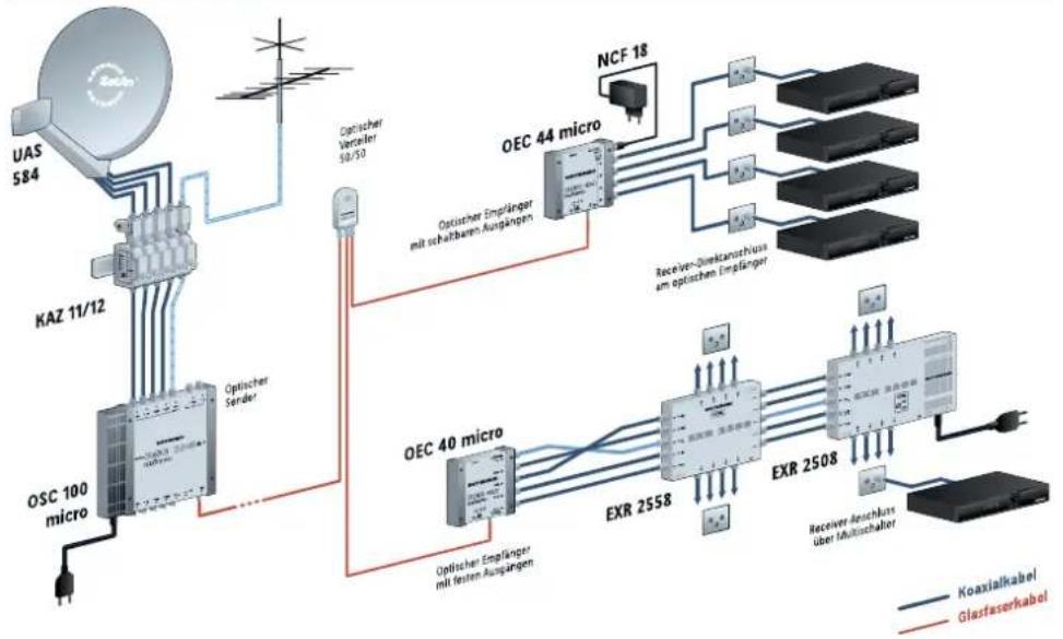
Branch diagram, split into 8 optical blocks
As shown in the "CLIKulator" program (http://clikulator.com/kathrein)

Installation example OSC 100 micro - OEC 44 micro - OEC 40 micro (symbolic representation)
Electronic equipment
Electronic equipment is not domestic waste – in accordance with directive 2012/19/EU OF THE EUROPEAN PARLIAMENT AND THE COUNCIL dated 4th July 2012 concerning used electrical and electronic appliances, it must be disposed of properly. At the end of its service life, take this unit for disposal at a designated public collection point.
For your notes

- Features optical transmitter OSC 100 micro
- Features optical distribution receivers OEC 40 micro/OEC 44 micro
- Variants
- Product description
- Installation and safety instructions
- Mounting
- Risk of material damage to the device!
- Equipotential bonding terminal
- Current-carrying device
- SIMPLIFIED EU DECLARATION OF CONFORMITY
- System functions
- Notes on planning the fibre optic system
- Handling optical components
- When dealing with optical waveguides:
- Cleaning optical connections:
- Input level optical transmitter OSC 100 micro
- TV (DTT/CATV) ⇔ DVB-T, Cable TV
- FM and DAB+
- SAT
- Input level:
- Differing levels within a satellite level:
- Input level optical receivers OEC 40 micro/OEC 44 micro
- Output level optical receiver OEC 40 micro/OEC 44 micro
- Application example
- Branch diagram, split into 8 optical blocks
- Electronic equipment
Brand : KATHREIN
Model : OEC 40 micro
Category : Antenna