
JKD101SPD - Surge protector HAGER - Free user manual and instructions
Find the device manual for free JKD101SPD HAGER in PDF.


| Brand | Hager |
| Model | JKD101SPD |
| Product Type | Surge Protection Device (SPD) |
| Surge Protection Type | Type I+II or Type II |
| Rated Current | 125 A |
| Number of Poles | 3P + N |
| Module Width | 4 modules (approx. 72 mm) |
| Mounting Type | DIN rail |
| Enclosure Rating | IP20 (typical) |
| Operating Temperature | -25°C to +60°C (typical) |
| Standards Compliance | IEC 61643-11 (typical) |
| Connection Type | Screw terminals |
| Torque Setting | 3.5 Nm |
| Status Indicator | Yes (visual) |
| Earth Connection | Copper earth link included |
| Neutral Connection | Neutral link included |
| Phase Connections | L1, L2, L3 phase links included |
| Installation Location | Power and lighting boards |
| Installation Requirements | Must be installed by an electrically skilled person |
| Included Accessories | Copper earth link, earth screws, KRN199 terminal blocks, ZB0220 M6 carp nut, neutral link, phase links, M5 screw & washers |
| Warranty | 5 years (typical) |
Frequently Asked Questions - JKD101SPD HAGER
User questions about JKD101SPD HAGER
0 question about this device. Answer the ones you know or ask your own.
Ask a new question about this device
Download the instructions for your Surge protector in PDF format for free! Find your manual JKD101SPD - HAGER and take your electronic device back in hand. On this page are published all the documents necessary for the use of your device. JKD101SPD by HAGER.
USER MANUAL JKD101SPD HAGER
JKD1 Surge Protection Instructions
Instruction leaflet for fitting 125A Surge Protection in Power and lighting boards
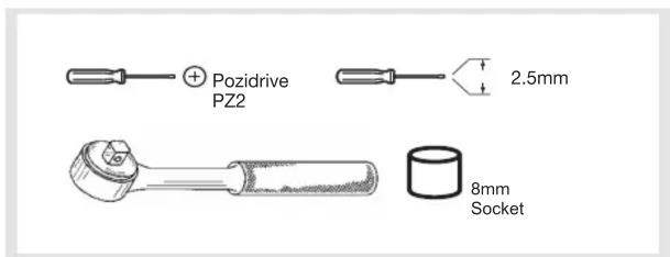
Parts list:
- 1 x Type I+II or Type II Surge Protection device
- 1 x Copper Earth Link
- 2 x Hex head Earth screws
- 3 x KRN199 Terminal block
- 1 x ZB0220 M6 Carp Nut
- 1 x Neutral link
- 3 x L1/L2/L3 Phase links
- 1 x M5 Hex head screw & washers

Clip the 4 module surge protection device to the dinrail next to the incomer. Fit the 3 KRN199 terminal block's to the first 3 phases on the left hand side of the busbar stack as shown above and torque to 3.5Nm.

Place the copper earth component into the bottom two cage terminals of the surge protection device and secure to 3.5Nm.
Use the 2 high torque screws provided to then secure the earth link to the base at 3.5Nm.

Secure the 3 brown cables to the terminals of the Surge protection device and the corresponding KRN devices L1/L2/L3 and torque to 3.5Nm.
Secure the Neutral cable to the Surge device to 3.5Nm and use the M5 hex head screw with washers to secure the ring terminal to the neutral bar next to the factory fitted neutral and secure to 3.5Nm.
'Ensure that when re-fitting the shroud that the left hand side is cut out to avoid clashing with the Surge protection cables'
The device may only be connected and installed by an electrically skilled person. National standards and safety regulations must be observed.
The device must be checked for external damage prior to installation. If any damage or other defects are detected in this check, the device must not be installed.
Its use is only permitted within the limits shown and stated in the installation instructions.
Opening or otherwise tampering with the device invalidates the warranty.


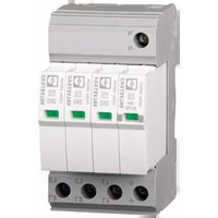
Brand : HAGER
Model : JKD101SPD
Category : Surge protector