Filter 8 - Synthesizer Joranalogue - Free user manual and instructions
Find the device manual for free Filter 8 Joranalogue in PDF.


| Product Type | Eurorack synthesizer module (VCF/VCO/VCLFO/slew modifier) |
| Dimensions (H x W x D) | 128.5 x 60.6 x 43 mm (including power cable depth 30 mm) |
| Weight | Module: 175 g; including packaging: 250 g |
| Power Requirements | +12V: 75 mA, -12V: 75 mA; reverse polarity protection (MOSFET) |
| All Inputs Impedance | 100 kΩ |
| All Outputs Impedance | 0 Ω (compensated) |
| Frequency Range (Audio Mode) | 22 Hz to 22 kHz (with fine knob centered) |
| Frequency Range (LF Mode) | 2.8 mHz (6 minute period) to 180 Hz |
| Key Features | 8-phase VCO, 4-pole cascaded LP core, pole mixing (HP, BB+N, phaser, BP), ping generator, hold, exponential and linear FM, volt/oct tracking, resonance compensation |
| Outputs (Simultaneous) | LP1, LP2, LP3, LP4, HP, BB+N, Phaser, BP4 (each with LED indicators) |
| Control Interface | Coarse/fine frequency, resonance, FM bipolar knobs, range switch, gain compensation switch, hold toggle, AC switch, trim pots (V/oct & resonance) |
| Inputs | 2x signal inputs, V/oct FM, exponential FM, linear FM (with AC coupling), resonance CV, hold gate, ping trigger |
| Front Panel | Milled 2 mm aluminium with non-erasable graphics |
| Mounting | Eurorack standard, 12 HP, 3 U; includes screws and washers |
| Included Accessories | Product card, 16-to-10 pin power cable, mounting hardware, protective cotton bag |
| Maintenance | Clean with dry cloth; calibration via front-panel trimmers; no user-serviceable internal parts |
| Safety | Reverse polarity protection; standard Eurorack power precautions |
| Spare Parts & Repairability | Contact dealer or support@joranalogue.com; calibration trimmers adjustable; no field-replaceable parts listed |
| Country of Manufacture | Belgium |
| Support | Email: support@joranalogue.com; mention serial number |
| User Manual Version | 2018-10-30 |
| Model Revision | Revision C (initial), D (LFM fix) |
Frequently Asked Questions - Filter 8 Joranalogue
User questions about Filter 8 Joranalogue
0 question about this device. Answer the ones you know or ask your own.
Ask a new question about this device
Download the instructions for your Synthesizer in PDF format for free! Find your manual Filter 8 - Joranalogue and take your electronic device back in hand. On this page are published all the documents necessary for the use of your device. Filter 8 by Joranalogue.
USER MANUAL Filter 8 Joranalogue
Representing the cutting edge in modular analogue voltage controlled filter (VCF) design, Filter 8 offers more possibilities and higher fidelity in 12 HP than ever before.
Starting from the classic OTA-style 4-pole cascaded lowpass (LP) topology, Filter 8 features separate LP outputs, each with their own character. Additional filter responses are achieved by pole mixing: 1-pole highpass, a special band boost and notch response, phase shifter and 4-pole bandpass. All outputs are available simultaneously.
Key to Filter 8's performance is the innovative resonant feedback circuit. By increasing the resonance, all outputs will resonate at the filter frequency, without any low frequency response loss. At higher resonance levels, self-oscillation is achieved, turning the module into an excellent 8-phase sine wave voltage controlled oscillator (VCO) with temperature and switchable gain compensation, low distortion, constant amplitude and accurate frequency tracking over at least 5 octaves. At sub-audio frequencies, Filter 8 can function as an 8-output voltage controlled slew modifier or 8-phase low frequency oscillator (LFO).
Simultaneous exponential and linear frequency modulation is possible, for classic FM tones or chaotic modulation. A hold feature is also provided, 'freezing' the output voltages manually or under gate control. This is useful for halting modulations, or as a sync-like effect at audio frequencies. The dedicated 'ping' input allows you to easily create crisp percussive sounds with different timbres.
While rooted in the legacy of classic synthesisers, Filter 8 provides a new approach to musical signal generators and modifiers: instead of simply a VCF, VCO, slew modifier or VCLFO, a single analogue module can now be any of those, and anything in between.
CONTENTS
In the Filter 8 box, you'll find:
- Product card, stating serial number and production batch.
■ 16-to-10-pin Eurorack power cable. - Mounting hardware: two black M3 x 6 mm hex screws, two black nylon washers and a hex key.
- The Filter 8 module itself, in a protective cotton bag.
If any of these items are missing, please contact your dealer or support@joranalogue.com.
CONTROLS & CONNECTIONS
1 FREQUENCY RANGE SWITCH
This switch determines over which frequency range Filter 8 will operate: low frequency (slew modifier/VCLFO) or audio frequency (VCF/VCO).
2 COARSE AND FINE FREQUENCY KNOBS
The filter/oscillator frequency is determined by these knobs. In standard audio mode, with the fine knob centred, the coarse knob has a range of 22 Hz to 22 kHz. The fine knob's range is 5 % of the coarse knob (6 semitones in audio mode).
In low frequency mode, the total range is 2.8 mHz (a period of 6 minutes) to 180 Hz, with 1 Hz when both knobs are centred.
3 RESONANCE KNOB
The resonance knob controls a feedback path from the filter output back to the input, causing the filter frequency to be emphasised. Filter 8's design includes an innovative resonance circuit: by increasing this parameter, all outputs will start to resonate at the filter frequency, without any low frequency response loss.
At higher feedback levels, self-oscillation will be achieved, turning the module into an excellent 8-phase sine wave VC(LF)O.
4 VOLT PER OCTAVE FM INPUT
This input is used to modulate the frequency in an exponential fashion, with a standard 1 volt per octave response. This enables accurate audio pitch in filter or oscillator mode. In the low range, the sensitivity is increased to approximately 0.66 volt per octave.
5 EXPONENTIAL FM INPUT AND KNOB
This second exponential FM input includes a polariser knob to set the modulation depth, with 0 in the centre, +1 volt per octave maximum and -1 volt per octave minimum in audio mode. In low mode, the sensitivity is increased to approximately 0.66 volt per octave.
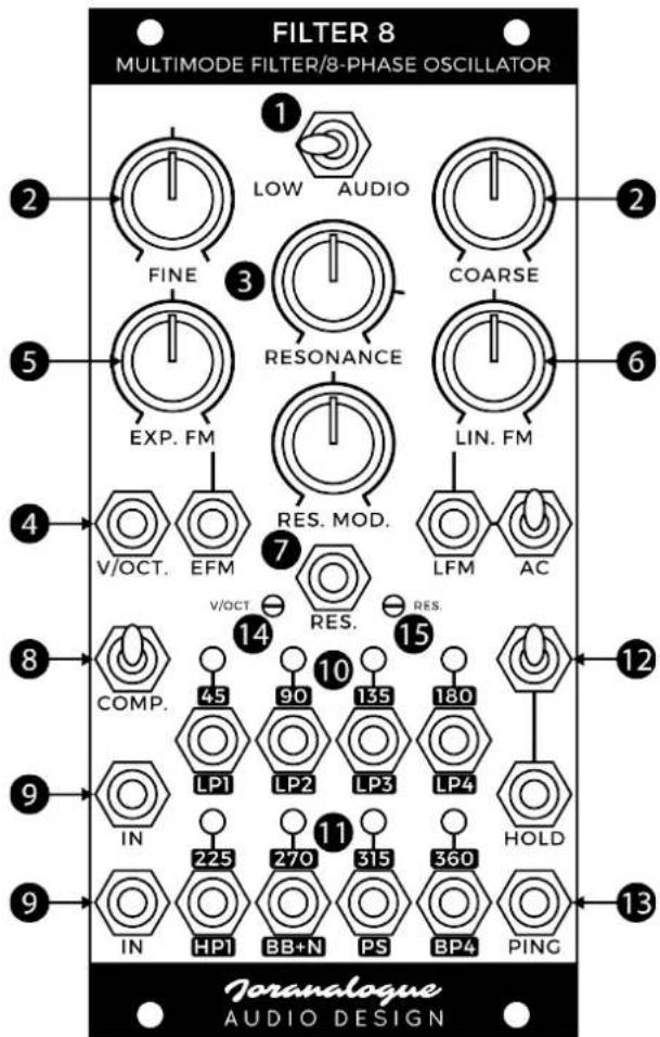
6 LINEAR FM INPUT, KNOB AND AC SWITCH
In addition to standard exponential FM, simultaneous linear frequency modulation is possible as well. This form of FM is well-known for being more 'tonal' in VCO mode, limiting the perceived shift in fundamental pitch as the FM depth is increased.
This FM input also features a polarised depth knob. The sensitivity ranges to approximately ±7% frequency deviation per volt.
Enable the AC switch to AC-couple the LFM input. This rejects any DC offset or very low frequency content that may be present in the modulation signal, preventing a fundamental pitch shift from appearing during audio rate modulation.
7 RESONANCE MODULATION INPUT AND KNOB
The resonance amount can be modulated through this input, with +5 V corresponding to maximum resonance. The modulation knob range is bipolar, just like the FM inputs.
8 GAIN COMPENSATION SWITCH
By default, each output is at unity gain with respect to the signal inputs. This is very useful when processing audio or CV. However, when Filter 8 is used in oscillator mode, all outputs resonate at different amplitudes. For this reason, the outputs are equipped with gain compensation stages, enabled using this toggle switch. With the compensation turned on, all output signals will have the same amplitude.
9 SIGNAL INPUTS
Connect the signal(s) to be filtered here. These identical inputs are mixed together, which can simplify certain patches as it often removes the need for a separate mixer module.
Filter 8 can clip and distort with certain input signals, especially if they are high-level, rich in harmonics and resonance is added. This is because all outputs are unity gain (when compensation is disabled), and removing harmonics can actually result in a signal's amplitude rising. This distortion can be used as a deliberate sonic effect. If you prefer to avoid it however, simply lower the amplitude(s) of the input signal(s).
To use Filter 8 purely as an oscillator, set the resonance to maximum and leave the input sockets unpatched.
10 LOWPASS OUTPUTS
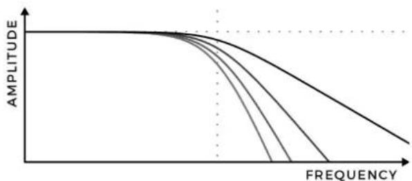
These are the outputs from the different stages inside the 4-pole lowpass filter core. Frequencies above the filter frequency (also known as 'cutoff', 'corner' or 'centre') will be attenuated. More stages means more attenuation, so each output has its own character: LP1 has the softest filter response (-6 dB per octave), while LP4 has the steepest (-24 dB per octave).
Electronic filters do not just affect amplitude, but phase as well. The phase shift at the filter frequency, relative to the input signal, is printed above each socket. Every additional filter stage adds 45^ of phase shift. As a result, the sine waves generated at the outputs in self-oscillation will be separated by 45^ between adjacent stages.
The LEDs at the output sockets show the real-time output voltages, lighting up red for positive and blue for negative. Note that DC offset voltages may be visible at the outputs, especially at extremely low frequencies. This is a result of the circuit topology and is considered normal behaviour.
The image below illustrates the amplitude responses of the four lowpass outputs, superimposed. The vertical dotted line denotes the filter frequency; the horizontal unity gain. Both axis are logarithmic.
line
| FREQUENCY | AMPLITUDE | | --------- | --------- | | 0 | 1.0 | | 1 | 0.95 | | 2 | 0.85 | | 3 | 0.75 | | 4 | 0.65 | | 5 | 0.55 | | 6 | 0.45 | | 7 | 0.35 | | 8 | 0.25 | | 9 | 0.15 | | 10 | 0.05 |11 POLE-MIXING OUTPUTS
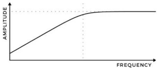
Using pole-mixing, additional filter responses are derived from the standard lowpass stages. The first is a 1-pole highpass output, offering relatively gentle highpass filtering. It will resonate at 225^ .
line
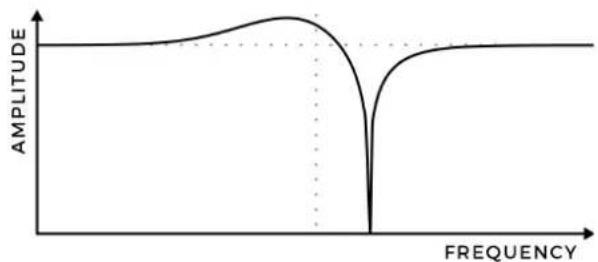
| FREQUENCY | AMPLITUDE | | --------- | --------- | | Low | Low | | Mid | Medium | | High | Peak |The second pole-mixing output is a special band boost and notch response. This boosts frequencies just below the filter frequency, and cuts those just above it. At high resonance settings, wavefolder-type sounds can be generated. It will resonate at 270°.
line
| FREQUENCY | AMPLITUDE | | --------- | --------- | | 0 | 0 | | Peak | High | | Low | 0 | | High | 0 |Next is the phase shifter output. It consists of a 3-pole allpass response, mixed together with the input signal. This creates a combined highpass and notch response, essentially a one-stage phaser effect. It will resonate at 315^ .
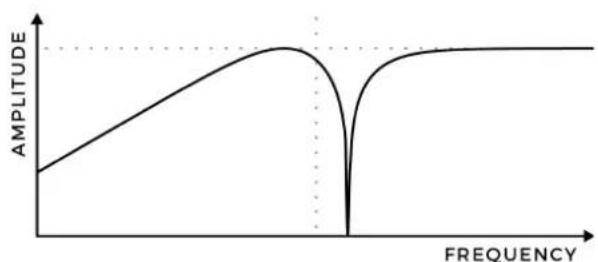
line
| FREQUENCY | AMplitude | | --------- | --------- | | Low | Low | | Peak | High | | High | 0 |The final pole-mixing output is a 4-pole bandpass response, selecting a band of frequencies around the filter frequency. It will resonate at 360^ (equal to 0^ , so no phase shift).
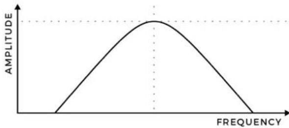
line
| FREQUENCY | AMPLITUDE | | --------- | --------- | | 0 | 0 | | Peak | 1 | | 1 | 0 | | 2 | 0 |By plotting the voltages over time of all outputs in self-oscillation, the 8-phase relationship between them becomes visible. With gain compensation enabled, all generated sine waves will have the same amplitude. While the outputs will sound identical on their own, having access to phase-separated signals opens up many advanced patching possibilities.
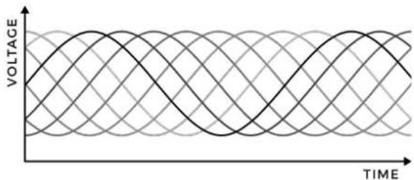
line
| TIME | VOLTAGE | |------|---------| | 0 | 0 | | 1 | 0.5 | | 2 | 1 | | 3 | 0.5 | | 4 | 0 | | 5 | -0.5 | | 6 | 0.5 | | 7 | 1 | | 8 | 0.5 | | 9 | 0 | | 10 | -0.5 | | 11 | 0.5 | | 12 | 1 | | 13 | 0.5 | | 14 | 0 | | 15 | -0.5 | | 16 | 0.5 | | 17 | 1 | | 18 | 0.5 | | 19 | 0 | | 20 | -0.5 | | 21 | 0.5 | | 22 | 1 | | 23 | 0.5 | | 24 | 0 | | 25 | -0.5 | | 26 | 0.5 | | 27 | 1 | | 28 | 0.5 | | 29 | 0 | | 30 | -0.5 | | 31 | 0.5 | | 32 | 1 | | 33 | 0.5 | | 34 | 0 | | 35 | -0.5 | | 36 | 0.5 | | 37 | 1 | | 38 | 0.5 | | 39 | 0 | | 40 | -0.5 | | 41 | 0.5 | | 42 | 1 | | 43 | 0.5 | | 44 | 0 | | 45 | -0.5 | | 46 | 0.5 | | 47 | 1 | | 48 | 0.5 | | 49 | 0 | | 50 | -0.5 | | 51 | 0.5 | | 52 | 1 | | 53 | 0.5 | | 54 | 0 | | 55 | -0.5 | | 56 | 0.5 | | 57 | 1 | | 58 | 0.5 | | 59 | 0 | | 60 | -0.5 | | 61 | 0.5 | | 62 | 1 | | 63 | 0.5 | | 64 | 0 | | 65 | -0.5 | | 66 | 0.5 | | 67 | 1 | | 68 | 0.5 | | 69 | 0 | | 70 | -0.5 | | 71 | 0.5 | | 72 | 1 | | 73 | 0.5 | | 74 | 0 | | 75 | -0.5 | | 76 | 0.5 | | 77 | 1 | | 78 | 0.5 | | 79 | 0 | | 80 | -0.5 | | 81 | 0.5 | | 82 | 1 | | 83 | 0.5 | | 84 | 0 | | 85 | -0.5 | | 86 | 0.5 | | 87 | 1 | | 88 | 0.5 | | 89 | 0 | | 90 | -0.5 | | 91 | 0.5 | | 92 | 1 | | 93 | 0.5 | | 94 | 0 | | 95 | -0.5 | | 96 | 0.5 | | 97 | 1 | | 98 | 0.5 | | 99 | 0 | | | |12 HOLD GATE INPUT AND SWITCH
The hold feature ‘freezes’ the filter core, slowing it down to near-standstill until the hold is released. This is useful for halting modulations, or as a sync-like effect at audio frequencies.
By default, the feature can be manually toggled using the toggle switch. It can also be controlled from an external gate signal on the 'hold' input. When the socket is used, the switch enables or disables the input.
Filter 8's hold input is uniquely designed to be driven reliably even from weak, slow, bipolar signals. It features Schmitt action, with a +2 V low and +3 V high logic threshold.
13 PING INPUT
Filter 8 includes a built-in transient generator to create 'filter ping' sounds. To use this feature, set the resonance on the verge of self-oscillation. This point is typically found just past 3 o'clock, as indicated on the front panel.
A rising edge at the ping input, reaching above +3 V. will ‘strike’ the filter core, creating a crisp percussive sound. The amplitude and decay time are set by the frequency and resonance parameters. Each output will generate a different ping timbre. For example, the lowpass outputs will have a pronounced transient, useful for synthesising kick drums. The bandpass output will be the purest, more suitable for bongo-type sounds.
Gain compensation should be disabled, to avoid the outputs distorting at the transient (except for output BB+N). The ping generator is designed to reliably create ping tones, no matter which kind of signal is used to drive it.
Additionally, the ping feature can be used in LF mode to trigger multi-phase decaying sine wave modulations.
14 VOLT PER OCTAVE TRIMMER
This trim potentiometer is used to calibrate the module's pitch tracking. Since it is accessible from the front panel, calibration can be easily performed without removing the module from the system. Each module is individually calibrated during production; do not adjust this trimmer if not needed.
Should you find your Filter 8 to be out of tune, set it to oscillator mode (no input signal, maximum resonance, range switch to audio, compensation enabled). Set the coarse frequency knob to about 20 % of its range (9 o'clock), and the fine knob in the centre position.
Make sure Filter 8 has been powered for at least 20 minutes at a stable ambient temperature. Now connect any output to a calibrated digital tuner. The volt per octave input signal should switch between 0 V and a precision +3 V source, toggled automatically or by hand. Using a dedicated trimming tool or standard 2.5 mm flat screwdriver, adjust the trimmer until the interval between both states is exactly 3 octaves.
15 RESONANCE TRIMMER
The second trim potentiometer sets the self-oscillation amplitude at maximum resonance. Use the same settings as for the V/oct. calibration procedure and display the BP4 output signal on an oscilloscope. Adjust the trimmer until the sine wave's amplitude is exactly 10 V_pp .
Although the volt per octave tracking is temperature-compensated, the resonance amplitude is not. It will change slightly with ambient temperature, as in any other analogue VCF. If an accurate 10 V_pp amplitude is required, recalibrate this trimmer whenever the temperature changes.
At low settings of this trimmer, Filter 8 will not be able to achieve self-oscillation. If your module can't self-oscillate, an improperly adjusted resonance trimmer is probably the reason why.
PATCH IDEAS
RESONATING ENVELOPES
Add interest to your envelopes by processing them through Filter 8. If the envelope has an amplitude of above +5 V, attenuate it first and then patch it to a Filter 8 signal input. The processed envelope is available at the LP1 output.
With the low frequency range active, you can slew the envelope and introduce some resonance to add 'bounce' to transients. Switch to the audio range to superimpose an audio-frequency component to the low frequency envelope for a unique combined modulation signal. Don't forget to try out the other filter outputs as well!
HOLD MODULATION
Using the hold input for audio-frequency modulation creates unique tones, somewhere between linear FM and standard oscillator sync. With Filter 8 in oscillator mode (no input, audio range, maximum resonance), apply an audio signal to the hold input and engage the switch.
Tune Filter 8 and the modulation source to a just interval, and apply volt per octave FM to both to create 'bell' or 'synthetic bass' tones reminiscent of vintage digital FM synthesisers.
If the hold signal source is a pulse wave, you can additionally modulate the pulsewidth to control the 'depth' of the hold effect.
RESPONSE BLENDING
Filter 8's multimode outputs are created using pole mixing, combining the input and lowpass outputs signals in precise ratios and polarities. This technique can be recreated externally: using a mixer module, add together various outputs to experiment with creating your own responses.
Use a voltage controlled mixer and apply different modulations to the channels for dramatic effect.
FEEDBACK DRIVE
Many synthesiser filters include an input overdrive circuit. While this is not present on Filter 8, the sound of an overdriven filter can still be easily created, and with much expanded sonic possibilities, using feedback patching.
With Filter 8 filtering an external audio signal, send the LP4 output to an attenuator, and then back into the spare input socket. The attenuator controls the amount of 'drive'.
Experiment with using different responses for audio output and feedback. Replace the attenuator by a VCA for voltage control over the tone.
SAW WAVE OSCILLATOR
Another application for feedback is changing the waveshape in oscillator mode. Patch the BP4 output to the exponential FM input. The EFM depth now determines the waveshape. At maximum modulation depth, the LP2 and BB+N output signals will be near-perfect saw/ramp waves.
The other outputs provide additional interesting waveshapes, ranging from rectified sine waves to curved saws. Note that the feedback depth also affects the volt per octave pitch tracking.
SPECIFICATIONS
MODULE FORMAT
Doepfer A-100 'Eurorack' compatible module 3 U, 12 HP, 30 mm deep (inc. power cable)
Milled 2 mm aluminium front panel with non-erasable graphics
MAXIMUM CURRENT DRAW
+12 V: 75 mA
-12 V: 75 mA
POWER PROTECTION
Reverse polarity (MOSFET)
I/O IMPEDANCE
All inputs: 100 kΩ
All outputs: 0 Ω (compensated)
OUTER DIMENSIONS (H X W X D)
128.5 x 60.6 x 43 mm
MASS
Module: 175 g
Including packaging and accessories: 250 g
SUPPORT
As all Joranalogue Audio Design products, Filter 8 is designed, manufactured and tested with the highest standards, to provide the performance and reliability music professionals expect.
In case your module isn't functioning as it should, make sure to check your Eurorack power supply and all connections first.
If the problem persists, contact your dealer or send an email to support@joranalogue.com. Please mention your serial number, which can be found on the product card or on the module's rear side.
REVISION HISTORY
Revision D: resolved linear FM 'freeze' issue which occurred when voltages of around +10 V were applied to the LFM CV.
Revision C: initial release.
With compliments to the following fine people, who helped to make Filter 8 a reality!
Ben 'DivKid' Wilson Björn Jauss
Boris Uytterhaegen Gregory Delabelle
Jan D'Hooghe Jens Van Daele
Everyone at Wired Electronics
Filter 8 User Manual
version 2018-10-30
21 ^st Century Analogue Synthesis—Made in Belgium
© 2018
Joranalogue
AUDIO DESIGN
info@joranalogue.com
https://joranalogue.com/
- CONTENTS
- CONTROLS & CONNECTIONS
- FREQUENCY RANGE SWITCH
- COARSE AND FINE FREQUENCY KNOBS
- RESONANCE KNOB
- VOLT PER OCTAVE FM INPUT
- EXPONENTIAL FM INPUT AND KNOB
- LINEAR FM INPUT, KNOB AND AC SWITCH
- RESONANCE MODULATION INPUT AND KNOB
- GAIN COMPENSATION SWITCH
- SIGNAL INPUTS
- LOWPASS OUTPUTS
- POLE-MIXING OUTPUTS
- HOLD GATE INPUT AND SWITCH
- PING INPUT
- VOLT PER OCTAVE TRIMMER
- RESONANCE TRIMMER
- PATCH IDEAS
- RESONATING ENVELOPES
- HOLD MODULATION
- RESPONSE BLENDING
- FEEDBACK DRIVE
- SAW WAVE OSCILLATOR
- SPECIFICATIONS
- MODULE FORMAT
- MAXIMUM CURRENT DRAW
- POWER PROTECTION
- I/O IMPEDANCE
- OUTER DIMENSIONS (H X W X D)
- MASS
- SUPPORT
- REVISION HISTORY
Brand : Joranalogue
Model : Filter 8
Category : Synthesizer