
Techno - Ventilateur domestique WESTINGHOUSE - Free user manual and instructions
Find the device manual for free Techno WESTINGHOUSE in PDF.


| Product Type | Pedestal Fan |
| Model | Techno |
| Brand | Westinghouse |
| Color | White/Black |
| Height (max) | 130 cm |
| Base Diameter | 40 cm |
| Fan Blade Diameter | 45 cm |
| Net Weight | 4.5 kg |
| Power Supply | 220-240 V ~ 50 Hz |
| Power Consumption | 50 W |
| Speed Settings | 3 speeds (Low, Medium, High) |
| Oscillation | Yes, 90° vertical tilt and 60° horizontal pivot |
| Timer | Up to 7 hours |
| Remote Control | Yes, with battery (CR2032 included) |
| Control Type | Touch panel + remote |
| Safety Features | Overheat protection, tilt-resistant base |
| Cleaning Instructions | Wipe with soft damp cloth; do not use abrasive cleaners |
| Spare Parts Available | Remote control, screws, fan blade set |
| Warranty | 2 years limited |
| Certification | CE, RoHS |
Frequently Asked Questions - Techno WESTINGHOUSE
User questions about Techno WESTINGHOUSE
0 question about this device. Answer the ones you know or ask your own.
Ask a new question about this device
Download the instructions for your Ventilateur domestique in PDF format for free! Find your manual Techno - WESTINGHOUSE and take your electronic device back in hand. On this page are published all the documents necessary for the use of your device. Techno by WESTINGHOUSE.
USER MANUAL Techno WESTINGHOUSE
Net Weight: 14.8 LBS
Peso Neto: 6.7 KGS

Intertek
OBSERVE THE FOLLOWING: READ AND SAVE THESE INSTRUCTIONS.
WARNING: TO REDUCE THE RISK OF FIRE, ELECTRIC SHOCK, ON PERSONAL INJURY, AMOUNT TO OUTLET BIG (AMENDED ACCEPTABLE FOR HAW SUPPORT OF 15.9 KG (35% LESS) OR LESS
AND USE MOUNTING SCREWS PROVIDED WITH THE OUTLET BOX AND/OR SUPPORT DIRECTLY FROM BUILDING STRUCTURE. MOST OUTLET BOXES COMMONLY USED FOR THE
SUPPORT OF LINAMINES ARE NOT ACCEPTABLE FOR PAN SUPPORT AND MAY NEED TO BE REPLINED. CONSULT A QUALIFIED ELECTRICANIE IN COUST
- Installation work and electrical wiring must be done by qualified personnel in accordance with all applicable codes and standards (WKSMAFFN 70-1999), including fire-rated construction.
- Use this unit only in the manner intended by the manufacturer. If you have any questions contact the manufacturer
- After making the wire connections, gently push connections into outlet box with wire rails pointing up. The wires should be spread apart with the grounded conductor and the equipment-grounding conductor on one side of the outlet box and connected conductors on the other side of the outlet box.
- Before you have installing the top switch power off at switch panel and look sensitive connecting means to current power from being switched on accurately. When the secure disconnecting means cannot be
- Stock price is trading on, as well as price of a stock price is trading on, but the stock price is trading on, and the stock price is trading on, but the stock price is trading on, and the stock price is trading on, but the stock price is trading on, and the stock price is trading on, but the stock price is trading on, and the stock price is trading on, but the stock price is trading on, but the stock price is trading on, and the stock price is trading on, but the stock price is trading on, but the stock price is trading on, but the stock price is trading on, but the stock price is trading on, but the stock price is trading on, but the stock price is trading on, but the stock price is trading on, but the stock price is trading on, but the stock price is trading on, but the stock price is trading on, but the stock price is trading on, but the stock price is trading on, but the stock price
- Be cautious load all instructions and safety information before installing your new fan. Review the accompanying assembly diagram.
- When cutting or drilling into wall or ceiling, it is not damage electrical wiring and other hidden units.
- Make sure the installation site you choose allows the fan blades to rotate without any instructions. Allow a minimum clearance of 7 feet from the floor to the trailing edge of the blade.
- To reduce the risk of fire, electric shock, or personal injury, this fan must be mounted to an outlet box marked suitable for fan support, and use the mounting survey provided with the outlet box. Mounting must
support at level 35 hrs. - WASHWEI Do not be a blade holder during installation to motors, balancing or during cleaning. Do not insert foreign object between rotating blades.
- Attach the mounting bracket using only the hardware supplied with the outlet box, Ian is only to be mounted to an outlet box marked "Acceptable for Ian Support".
- WAFENHE! To return the risk of fire or electric shock, do not use this fan with any solid state fan speed control device, or variable speed control.
- If this unit is to be installed over a tub or shower, it must be marked as appropriate for the application.
- MFBR place a switch where it can be reached from a tub or shower.
- The combustion air flow needed for safe operation of fuel-burning equipment may be affected by this unit's operation. Follow the heating equipment manufacturer's guideline safety standards such as those
published by the National Fire Protection Association (MFFA), and the American Society for Heating, Refrigeration and Air Conditioning Engineers (ASIRAF) and the local code authorities. - Before servicing or clean unit. Switch power off at Service and lock service disconnecting means to prevent power from being switched on accidentals. When the service disconnected means cannot be
closed, securely faster a prominent warning device, such as a tag, to the service panel. - Musture was must be checked and re-tightened where necessary before installation.
- The appliance is not intended for use by young children or infant persons without supervised. Young children should be supervised to ensure that they do not play with the appliance.
- The LFD Luminaire contains no Uf/
TOOLS REQUIRED
Phillips Screwdriver Wire Cutters Pliers Step Ladder
American Societs for Heating, Refrigeration and Air Conditioning Engineers, (AS/PAD) plus autorised delodigrolocal.
Notes: for picker using resalation, please refer to westinghouselighting.com for specialty for your copy of options. Notes: Puts reals on enelenses Indonesia who westinghouselighting are pan interne interne er.
Loosen set screws (1) in downroot coupling (2), insert downroot into downroot coupling. Make sure to align hole in downroot with the hole in downroot coupling. Install coupling cross pin (3) through coupling and downroot insert clump pin (4) into cross pin until it snaps into place. Tighten set screws (1) in coupling. Slide coupling cover (5) over the downroot coupling. PROCEED TO PAGE 11, STEP 11.
loosen downed hall (1) from downed (2) by remodeling set screw (3). Afoje la esfera de la vanilla vertical (1) de la vanilla vertical (2) quitando el tomillo (3).
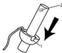
Slide downrod ball (1) off of downrod and remove pin (2). Deslice la esfera de la vanilla vertical (1) hasta separada de la vanilla vertical y quite el pasador (2).
natural_image
Illustration of hands using a tool to adjust or install a cylindrical object, with an arrow indicating the motion (no text or symbols present)He install pin into extended downrod, and slide downrod ball up to the top of the downrod. He install set screw to secure ball to downrod. Notes: Some extended downrods have a pre-drilled set-screw hole. If a pre-drilled hole is present in the extended downrod, tighten the set screw into the pre-drilled hole in the extended downrod. If no pre-drilled hole exists in the extended downrod, tighten the set screw against the downrod to secure the downrod ball. PROCEED TO PAGE #7, STEP 5.
Attach blades (1) to the blade bracket (2) using the blade screws (3) and washers (4)
natural_image
Illustration of two steps of heating a pot with a flame, no text or symbols presentPlace fan body with down rod pointing downward and motor positioned toward ceiling. Attach the fan blade bracket assembly onto the motor, line up the holes. In the blade bracket with the holes in the motor marked A-A, B-B, C-C, secure the blade box to the motor with motor screws permitted.
This remote control unit is equipped with 16 code combinations to present possible interference from or to other remote units. The frequency switches on your receiver and transmitter have been preset at the factory. Please recheck to make sure the switches on transmitter and receiver are set to the same position, any combination of settings will operate the fan as long as the transmitter and receiver are set to the same position.
Make wiring connections from the house and the motor to the remote receiver as shown above. Correct using wire nuts (provided).
natural_image
Line drawing of a hand holding a mechanical component (no text or symbols)Once wiring step has been completed, side the wired remote receiver in between the mounting bracket and the top of the downrod ball for downrod fans.
Loosen the 2 screws on the bottom of mounting bracket. I do not removal Raise the canopy up and align the keyholes on the bottom of the canopy with the 2 screws on the bottom of mounting bracket. Rotate the canopy until both screws from the mounting bracket drop into the slot recesses. Tighten screws securely.
natural_image
Technical line drawing of a turbine blade assembly with labeled components (no text or symbols)Attach the light kit plate (2) to the light kit plate support (1) by placing the keyslot holes from the light kit plate onto the two protruding screw heads from the light kit plate support. Twist the light kit plate clockwise until the screwheads engage the keyslots. Install the screw removed from light kit plate support (step19) into the closed hole in the light kit plate. Tighten all screws to complete attachment of the light kit plate.
Remove one of the 3 screws from the light kit plate (1), and loosen (do not remove) the other two. Connect the wires from motor to the wires from the light kit (2) by using the 2-pin moles plug Attach the light kit (2) onto the light kit plate (1) by placing the key slot holes in the light kit (2) onto the two protruding screw heads on the light kit plate (1). Twist the light kit (2) until the screw heads engage the key slots. Install the screw removed from the light kit plate (1) into the closed hole in the light kit (2). Tighten all screws to complete the attachment of the light kit (2).
natural_image
Technical line drawing of a mechanical component with multiple views and a magnified inset showing detailed detail (no text or symbols)Remote Control Operation
- Fan Control—press and release. The remote control
operates the fan speed as follows: OFF - off; HIGH - high;
MED - medium high, MLOW - medium; LOW - low; - Light On/Off - press and release light button.
Speed setting for warm tool weather dependence on loads such as main size, cutting height, number of legs and soon. The side switch controls direction, forward or reverse.
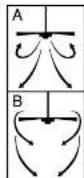
When weathered down action - (forward) For turns counter-cobator direction, a downward air flow comes a curing effect as shown in Humming & This allows you to set your air condition on a higher pressure setting without affecting your comfort.
Cool weather-up problem - otherwise, I am turns decrease direction. An upward airflow moves warm or off the ceiling area as strain in illustration 2. This allows you to set your ceiling and on a lower ceiling without affecting your needs.
NOTE: Turn off and wait for fun to stop before changing the setting of the forward reverse side switch.
Maintenance
- Because of the far's natural movement, some connections may become loose. Check the support connections, brackets, and blade
- Clear water but periodic heat to the maining in any appearance over the years. Do not use water-snew drying. The cold decrease
The matter, or the word, or a single source of the natural choice. - Use only a soft brush or light-free cloth to avoid touching the finish. The plating is walled with a copper coating to minimize
- 2017
• In particular, the following is the most important factors:
TROUBLESHOOTING GUIDE
If you have difficulty operating your new ceiling fan, it may be the result of incorrect assembly, installation, or wiring. In some cases, these installation errors may be mistaken for tickets. If you experience any faults, please check this Double Steering Chart. It is a problem cannot be remedied, please result with your authorized escalation and do not attempt any electrical room yourself.
TROUBLE
SUGGESTED REMEDY
-
If fan does not start:
-
check main and branch circuit fuses or circuit breakers.
-
check wire connections as performed in step #15 of installation.
CAUTION: Make sure main power is turned off.
- Make sure forward/beverse switch is firmly in up or down position.
Fan will not operate when switch is in the middle.
- If the fan still will not start, contact a qualified electrician.
Do not attempt to troubleshoot internal electrical connections yourself.
-
If fan sounds noise:
-
check to make sure all screws in motor housing are snug (not over tightened).
-
check to make sure the screws which attach the fan blade holder to the motor are tight.
-
Some fan motors are sensitive to signals from Solid State variable speed controls.
DO NOT USE a Solid State variable speed control.
-
Allow "break-in" period of 24 hours. Most noises associated with a new fan will disappear after this period.
-
If fan watchles:
All blazes are weighted and grouped by weight. Natural woods vary in density which could cause the fan to wobble even though all blades are weight-matched. The
following procedures should eliminate most of the wobble. check for wobble after each step.
-
check that all blades are screwed firmly into blade holders.
-
check that all blade holders are tightened securely to motor
-
Make sure that canopy and mounting bracket are tightened securely to ceiling joint.
-
If blade wobble is still noticeable, interchanging two adjacent side by side blades can redistribute the weight and possibly result in smoother operation.
-
If light does not work:
-
check to see that the wire connections in the switch housing are connected
-
check for faulty light bulbs.
-
If light kit will still not operate, contact a qualified electrician for assistance.
(in its prices based)
3.50 USF income of a broader sector of state funds.
ETL-ES-Techno-WH14
Westinghouse Lighting, Philadelphia, PA 19154-1029, U.S.A. www.westinghouselighting.com
W, WESTINGHOUSE, and INNOVATION YOU CAN BE SURE OF are trademarks of Westinghouse Electric Corporation. Used under licensee by Westinghouse Lighting All rights reserved. Made in China

Brand : WESTINGHOUSE
Model : Techno
Category : Ventilateur domestique