
Great Falls - Household Fan WESTINGHOUSE - Free user manual and instructions
Find the device manual for free Great Falls WESTINGHOUSE in PDF.


| Product Type | Ceiling Fan |
| Brand | Westinghouse |
| Model | Great Falls |
| Net Weight | 17.16 lbs (7.8 kg) |
| Installation Location | Wet locations when used with GFCI protected circuit |
| Minimum Clearance | 7 ft from floor to trailing edge of blade |
| Motor Type | Permanently lubricated bearings |
| Speed Control | Pull chain (3 speeds: High, Medium, Low) or optional wall control |
| Direction Control | Reversible slide switch (forward/counterclockwise for cooling, reverse/clockwise for warming) |
| Light Kit Compatibility | Yes (requires blue wire connection; uses 9-pin molex plug) |
| Downrod Options | Standard downrod included; extended downrod available separately |
| Sloped Ceiling Compatible | Yes (requires special canopy kit from westinghouselighting.com) |
| Safety Rating | Intertek listed; suitable for fan support outlet box rated 35 lbs (15.9 kg) or less |
| Electrical Requirements | 120V AC; do not use with solid state fan speed control devices |
| Maintenance | Clean with soft brush or lint-free cloth; no water or oil required |
| Spare Parts | Blade holders, blades, light kits available via manufacturer |
| Country of Origin | Made in China |
Frequently Asked Questions - Great Falls WESTINGHOUSE
User questions about Great Falls WESTINGHOUSE
0 question about this device. Answer the ones you know or ask your own.
Ask a new question about this device
Download the instructions for your Household Fan in PDF format for free! Find your manual Great Falls - WESTINGHOUSE and take your electronic device back in hand. On this page are published all the documents necessary for the use of your device. Great Falls by WESTINGHOUSE.
USER MANUAL Great Falls WESTINGHOUSE
natural_image
Black and white photo of a four-blade ceiling fan with a headlamp (no text or symbols visible)Net Weight: 17.16 LBS
Peso Neto: 7.8 KGS

Intertek
SAFETY TIPS
OBSERVE THE FOLLOWING: READ AND SAVE THESE INSTRUCTIONS
WARNING: TO REDUCE THE RISK OF FIRE, ELECTRIC SHOCK, OR PERSONAL INJURY, MOUNT TO OUTLET BOX MARKED 'ACCEPTABLE FOR FAN SUPPORT OF 35 LBS (15.9 KG) OR LESS' AND USE MOUNTING SCREWS PROVIDED WITH THE OUTLET BOX AND/OR SUPPORT DIRECTLY FROM BUILDING STRUCTURE. MOST OUTLET BOXES COMMONLY USED FOR THE SUPPORT OF LUMINARIES ARE NOT ACCEPTABLE FOR FAN SUPPORT AND MAY NEED TO BE REPLACED. CONSULT A QUALIFIED ELECTRICIAN IF IN DOUBT.
- Installation work and electrical wiring must be done by qualified person(s) in accordance with all applicable codes and standards (ANSI/NFPA 70), including fire-rated construction.
- Use this unit only in the manner intended by the manufacturer. If you have any questions contact the manufacturer.
- After making the wire connections, gently push connections into outlet box with wire nuts pointing up. The wires should be spread apart with the grounded conductor and the equipment-grounding conductor on one side of the outlet box and ungrounded conductor on the other side of the outlet box.
- Before you begin installing the fan, switch power off at service panel and lock service disconnecting means to prevent power from being switched on accidentally. When the service disconnecting means cannot be locked, securely fasten a prominent warning device, such as a tag, to the service panel.
- Be cautious! Read all instructions and safety information before installing your new fan. Review the accompanying assembly diagrams.
- When cutting or drilling into wall or ceiling, do not damage electrical wiring and other hidden utilities.
- Make sure the installation site you choose allows the fan blades to rotate without any obstructions. Allow a minimum clearance of 7 feet from the floor to the trailing edge of the blade.
- To reduce the risk of fire, electric shock, or personal injury, this fan must be mounted to an outlet box marked suitable for fan support, and use the mounting screws provided with the outlet box. (Mounting must support at least 35 lbs.)
- WARNING! Do not bend blade holders during installation to motor, balancing or during cleaning. Do not insert foreign object between rotating blades.
- Attach the mounting bracket using only the hardware supplied with the outlet box. Fan is only to be mounted to an outlet box marked "Acceptable for Fan Support".
- WARNING! To reduce the risk of fire or electric shock, do not use this fan with any solid state fan speed control device, or variable speed control.
- If this unit is to be installed over a tub or shower, it must be marked as appropriate for the application.
- NEVER place a switch where it can be reached from a tub or shower.
- The combustion airflow needed for safe operation of fuel-burning equipment may be affected by this unit's operation. Follow the heating equipment manufacturer's guideline safety standards such as those published by the National Fire Protection Association (NFPA), and the American Society for Heating, Refrigeration and Air Conditioning Engineers (ASHRAE) and the local code authorities.
- Before servicing or cleaning unit, Switch power off at Service panel and lock service disconnecting means to prevent power from being switched on accidentally. When the service disconnecting means cannot be locked, securely fasten a prominent warning device, such as a tag, to the service panel.
- All set screws must be checked and re-tightened where necessary before installation.
- The appliance is not intended for use by young children or infirmed persons without supervision. Young children should be supervised to ensure that they do not play with the appliance.
- Suitable for use in wet locations when installed in a GFCI protected branch circuit.
- Use only with light kits marked 'suitable for use in wet locations'.
TOOLS REQUIRED
Phillips Screwdriver
Wire Cutters
Pliers
Step Ladder
natural_image
Abstract black-and-white geometric shape with no text or symbolsnatural_image
Pure mechanical cross-section diagram without any text, numbers, or symbolsFor normal ceilings
Para techo normales
natural_image
Pure mechanical diagram showing a lever and pivot (no text or symbols)Note: For sloped ceiling installation, please refer to westinghouselighting.com for specially designed canopy kit options.
MOUNTING BRACKET INSTALLATION
natural_image
Diagram of a mechanical component with bidirectional arrows indicating rotational motion (no text or symbols)natural_image
Illustration of a hand using a screwdriver to adjust or install a mechanical component (no text or symbols present)Install mounting bracket to outlet box in ceiling using the screws and washers provided with the outlet box.
If flush mount option is selected, proceed to page 8, step 6.
If installing downrod supplied with fan, proceed to page 9, step 8.
If installing with longer downrod than supplied with fan, proceed to page 10, step 10.
natural_image
Technical illustration of a mechanical component with a close-up inset showing internal detail (no text or symbols)Remove cotter pin and cross pin (5). Place downrod assembly (1) into canopy (2) and coupling cover (3). Feed the 3 motor wires though the downrod assembly (1). Insert the 3 motor wires separately through the 3 holes in the rubber downrod cover (4), and insert the grounding wire from the hanger ball through the 4th hole in the rubber downrod cover (4). Snap the rubber downrod cover over downrod hanger ball. This will prevent water from running through the downrod.
Insert downrod into downrod coupling. Make sure to align hole in downrod with the hole in downrod coupling. Insert pin (1) through coupling and downrod. Insert cotter pin (2) into pin until it snaps into place. Tighten the 2 coupling screws (3) in coupling. Slide coupling cover (4) over the downrod coupling. PROCEED TO PAGE 12, STEP 13.
Slide downrod ball (1) off of downrod and remove pin (2).
Deslice la bola de la varilla vertical (1) hasta separarla de la varilla vertical y quite el pasador (2).
EXTENDED DOWNROD OPTION
natural_image
Illustration showing two steps of a tool: one being adjusted to a handle, the other holding a tool with a magnified view (no text or symbols)Re-install pin into extended downrod, and slide downrod ball up to the top of the downrod. Re-install set screw to secure ball to downrod. Note: Some extended downrods have a pre-drilled set-screw hole. If a pre-drilled hole is present in the extended downrod, tighten the set screw into the pre-drilled hole in the extended downrod. If no pre-drilled hole exists in the extended downrod, tighten the set screw against the downrod to secure the downrod ball. PROCEED TO PAGE 9, STEP 8
Carefully lift fan assembly onto mounting bracket. Rotate fan until notch on downrod ball (1) engages the ridge on the mounting bracket (2). This will allow for hands free wiring.
natural_image
Technical line drawing of a mechanical component with no visible text or symbolsWith bracket holding fan assembly, make electrical connections using the following step for wiring instructions.
PULL CHAIN WIRING OPTION
From Fan:
From House:
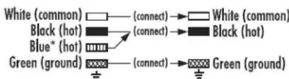
*Attach blue wire only if attaching light kit with fan.
Follow diagram above to make wiring connections for fan pull chain control.
WALL CONTROL WIRING OPTION
From Fan:
From House:
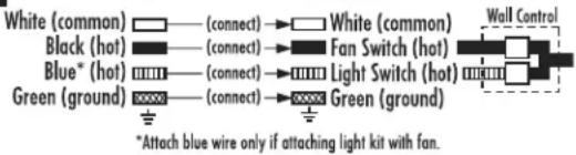
Follow diagram above to make wiring connections for wall control operation.
For flush mount fans, carefully lift fan up to the mounting bracket, making sure not to break any wire connections. For downrod fans, slide the canopy up to the mounting bracket.
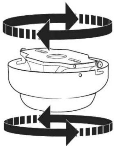
The canopy has two mating slots (1) and two mating holes (2). Position both slots on canopy directly under and in line with two screws in the mounting bracket (3). Lift the canopy, allowing the two screws and star washers to slide into the mating slots. Rotate the canopy clockwise until both screws from the mounting bracket drop into the slot recesses. Tighten screws securely. Install two screws and star washers into the mating holes of the canopy and tighten to secure the canopy to the mounting bracket.
Remove one of the screws on the switch housing (1), and loosen (do not remove) the other two. Connect the wires from switch housing (1) to the wires from the light kit (2), using the 9-pin molex plug, be sure to line up the indicating lines.
natural_image
Line drawing of a four-blade ceiling fan with a central hub and three blades (no text or symbols)Attach the light kit to the switch housing by placing the keyslot holes from the light kit onto the two protruding screw heads from the switch housing. Twist the light kit until the screwheads engage the keyslots. Install the screw removed from the switch housing (step 22) into the closed hole in the light kit. Tighten all screws to complete attachment of the light kit.
natural_image
Line drawing of a four-blade ceiling fan with a central hub and decorative base (no text or symbols)Attach the metal frame to the light kit by placing the key slot holes from the metal frame onto the two protruding screw heads from the light kit. Twist the metal frame until the screw heads engage the key slots. Install the screw removed from the light kit (step 25) into the closed hole in the metal frame. Tighten all screws to complete attachment of the metal frame with glass.
Assemble decorative fob and extension chains from hardware bag to fan pull chains by inserting end of chain into chain coupling. Confirm chains are held by lightly pulling both chains in coupling.
natural_image
Technical line drawing of a ceiling fan with labeled components (no text or symbols present)Remove the metal frame from the fan, the reverse switch (1) is locating on the light kit.
NOTE: Turn off and wait for fan to stop before changing the setting of the forward/reverse slide switch.
Turn on the power and check operation of fan. The pull chain controls the fan speeds as follows: 1 pull - high; 2 pulls - medium; 3 pulls - low; 4 pulls - off.
Speed settings for warm or cool weather depend on factors such as room size, ceiling height, number of fans and so on. The slide switch controls direction, forward or reverse.
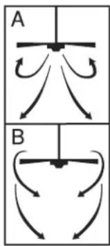
Warm weather/down position - (Forward) Fan turns counterclockwise direction. A downward air flow creates a cooling effect as shown in illustration A.
This allows you to set your air conditioner on a higher temperature setting without affecting your comfort.
Cool weather/up position - (Reverse) Fan turns clockwise direction. An upward airflow moves warm air off the ceiling area as shown in illustration B.
This allows you to set your heating unit on a lower setting without affecting your comfort.
NOTE: Turn off and wait for fan to stop before changing the setting of the forward/reverse slide switch.
Maintenance
- Because of the fan's natural movement, some connections may become loose. Check the support connections, brackets, and blade attachments twice a year. Make sure they are secure.
- Clean your fan periodically to help maintain its new appearance over the years. Do not use water when cleaning. This could damage the motor, or the wood, or possibly cause electrical shock.
- Use only a soft brush or lint-free cloth to avoid scratching the finish. The plating is sealed with a lacquer coating to minimize discoloration or tarnishing.
- There is no need to oil your fan. The motor has permanently lubricated bearings.
TROUBLESHOOTING GUIDE
If you have difficulty operating your new ceiling fan, it may be the result of incorrect assembly, installation, or wiring. In some cases, these installation errors may be mistaken for defects. If you experience any faults, please check this Trouble Shooting Chart. If a problem cannot be remedied, please consult with your authorized electrician and do not attempt any electrical repairs yourself.
TROUBLE
SUGGESTED REMEDY
-
If fan does not start:
-
Check main and branch circuit fuses or circuit breakers.
- Check wire connections as performed in step #15 or #16 of installation. CAUTION: Make sure main power is turned off.
- Make sure forward/reverse switch is firmly in up or down position. Fan will not operate when switch is in the middle.
-
If the fan still will not start, contact a qualified electrician. Do not attempt to troubleshoot internal electrical connections yourself.
-
If fan sounds noisy:
-
Check to make sure all screws in motor housing are snug (not over tightened).
- Check to make sure the screws which attach the fan blade holder to the motor are tight.
- Some fan motors are sensitive to signals from Solid State variable speed controls. DO NOT USE a Solid State variable speed control.
-
Allow "break-in" period of 24 hours. Most noises associated with a new fan will disappear after this period.
-
If fan wobbles:
All blades are weighed and grouped by weight. Natural woods vary in density which could cause the fan to wobble even though all blades are weight-matched. The following procedures should eliminate most of the wobble. Check for wobble after each step.
- Check that all blades are screwed firmly into blade holders.
- Check that all blade holders are tightened securely to motor.
- Make sure that canopy and mounting bracket are tightened securely to ceiling joist.
-
If blade wobble is still noticeable, interchanging two adjacent (side by side) blades can redistribute the weight and possibly result in smoother operation.
-
If light does not work:
-
Check to see that the wire connections in the switch housing are connected.
- Check for faulty light bulbs.
- If light kit will still not operate, contact a qualified electrician for assistance.
GUÍA PARA SOLUCIONAR PROBLEMAS
Westinghouse Lighting, Philadelphia, PA 19154-1029, U.S.A. www.westinghouselighting.com
W, WESTINGHOUSE, and INNOVATION YOU CAN BE SURE OF are trademarks of Westinghouse Electric Corporation Used under license by Westinghouse Lighting All rights reserved. Made in China

Brand : WESTINGHOUSE
Model : Great Falls
Category : Household Fan