
Solana - Ventilateur domestique WESTINGHOUSE - Free user manual and instructions
Find the device manual for free Solana WESTINGHOUSE in PDF.


| Product Type | Ceiling Fan |
| Brand | Westinghouse |
| Model | Solana |
| Net Weight | 14.54 lbs (6.6 kg) |
| Number of Blades | 2 |
| Light Kit Included | Yes |
| Bulb Type | E12 base, max 60W (2 bulbs included) |
| Remote Control | Yes, 16-code combination, includes wall bracket |
| Reversible Motor | Yes, forward/reverse slide switch |
| Speed Settings | 3 speeds (High, Medium, Low) |
| Mounting Type | Downrod mount (standard and extended) |
| Maximum Ceiling Slope | Pitched ceiling compatible (special canopy kit required) |
| Energy Compliance | Energy Policy Act 2005 compliant (light fixture limiter to 190W total) |
| Light Dimmer | Yes, continuous dimming via remote |
| Blade Balance Kit | Included |
| Motor Bearings | Permanently lubricated |
| Warranty | Not specified (typical 1-year limited) |
| Country of Origin | Made in China |
| Recommended Support | Outlet box rated for fan support (max 35 lbs) |
| Assembly Time | Approximately 35 minutes |
Frequently Asked Questions - Solana WESTINGHOUSE
User questions about Solana WESTINGHOUSE
0 question about this device. Answer the ones you know or ask your own.
Ask a new question about this device
Download the instructions for your Ventilateur domestique in PDF format for free! Find your manual Solana - WESTINGHOUSE and take your electronic device back in hand. On this page are published all the documents necessary for the use of your device. Solana by WESTINGHOUSE.
USER MANUAL Solana WESTINGHOUSE
natural_image
Modern double-decker airship with a curved wooden handle and metallic top (no text or symbols visible)Solana
by

Westinghouse
Table of Contents
Índice
Safety Information 2
Parts/Reference List 4
Installation Instructions 6
Net Weight: 14.54 LBS
Peso Neto: 6.6 KGS

Intertek
Please write model number
here for future reference:
WARNING - TO REDUCE THE RISK OF FIRE, ELECTRIC SHOCK, OR PERSONAL INJURY, MOUNT TO OUTLET BOX MARKED 'ACCEPTABLE FOR FAN SUPPORT OF 15.9 KG (35 LBS) OR LESS' AND USE MOUNTINGSCREWS PROVIDED WITH THE OUTLET BOX AND/OR SUPPORT DIRECTLY FROM BUILDING STRUCTURE. MOST OUTLET BOXES COMMONLY USED FOR THE SUPPORT OF LUMINARIES ARE NOT ACCEPTABLE FOR FAN SUPPORT AND MAY NEED TO BE REPLACED. CONSULT A QUALIFIED ELECTRICIAN IF IN DOUBT.

AdVERTENCIA - PARA REduCIR EL RIESGo de INCENdlo, dESCARGA ELECTRICA o LESloNES PERSoNALES, MoNTE EN uNA CAJA de EMBuTIR RoTuLAda "AdECuAdA PARA VENTILAdoRES de 15,9 KG (35 LB) o MENOs" u TILIZANdo LoS ToRNILLoS de MoNTAJE INCLuldoS CoN LA CAJA de EMBuTIR Y/o MoNTE dIRECTAMENTE EN LA ESTRuCTuRA del Edificio LA MAYoRIA de LAS CAJAS de EMBuTIR u TILIZADAS NoRMALMENTE CoN ARTEFACToS de ILuMINACIoN No SoN AdECuAdAS PARA VENTILAdoRES y DEBERIAN SER REEMPLAZAdAS. SI TIENE PREGUNTAS, CoNSuLTE A uN ELECTRICISTA CERTIFICAdo.
Before beginning assembly, installation or operation of product, make sure all parts are present. Compare parts with the Parts Reference List.
Estimated Assembly Time: 35 minutes (standard installation) Tools Required for Assembly: Phillips Screwdriver, Step Ladder. (not included)
natural_image
Pure mechanical cross-section diagram without any text, numbers, or symbolsFor normal ceilings
Para cielorrasos normales
natural_image
Abstract black-and-white geometric diagram with no text or symbolsNote: For pitched ceiling installation, please refer to westinghouselighting.com for specially designed canopy kit options.
NOTE: The reference list below assigns a letter to each part referenced in the assembly instructions. Use this reference as both a descriptive listing, as well as designation of the parts' final location.
| A | Motor | 1 |
| B | Flywheel (attached to motor) 2 | |
| C | Blade | 2 |
| D | Glass | 1 |
| E | Canopy | 1 |
| F | Mounting Bracket 1 | |
| G | Canopy Cover Ring 1 | |
| H | Downrod Ball 1 | |
| I | Downrod | 1 |
| J | Coupling (attached to motor) 1 | |
| K | Remote Transmitter 1 | |
| L | Remote Receiver 1 | |
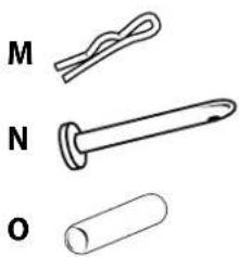
| M | Clamp Pin (attached to downrod) | 1 |
| N | Cross Pin (attached to downrod) | 1 |
| O | Cross Pin (in downrod ball) | 1 |
| P | Coupling Cover | 1 |
| Q | Set Screw (attached to downrod ball) | 1 |
| R | Set Screw (in coupling) | 2 |
| S | Screw (attached to mounting bracket) | 2 |
Part Description Quantity
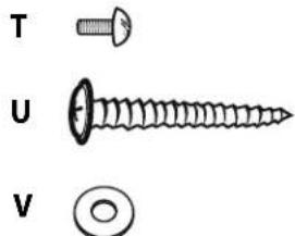
| T | Blade Screw (in hardware bag) | 7 |
| U | Wood Screw (in hardware bag) | 2 |
| V | Metal Washer | 9 |
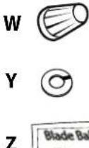
| W | Wire Nut | 4 |
| X | Bulb | 2 |
| Y | Lock Washer (for wood screws) | 2 |
| Z | Blade Balance Kit | 1 |
natural_image
Simple line drawings of three labeled objects: a coiled spring, a pen-like object with a curved handle, and a cylindrical object (no text or symbols)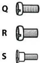

Parts missing or damaged? Please visit www.westinghouselighting.com/support/Questions or problems installing your fan? Please contact your local electrician.
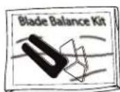
Unpack and inspect fan carefully to be certain all contents are included.
1
Turn off power at fuse box to avoid possible electrical shock.
Use metal outlet box suitable for fan support (must support 35 lbs). Before attaching fan to outlet box, ensure the outlet box is securely fastened by at least two points to a structural ceiling member (a loose box will cause the fan to wobble).
2
Install mounting bracket (F) to outlet box in ceiling using the screws and washers provided with the outlet box.
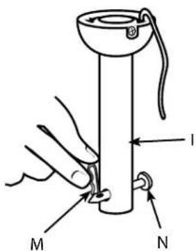
Remove clamp pin (M) and cross pin (N) from downrod (I).
natural_image
Line drawing showing a cabinet with internal compartments and an open electrical panel with a hand interacting (no text or symbols)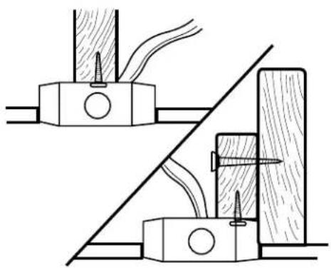
natural_image
Technical line drawing of mechanical assembly with no visible text or symbols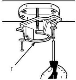
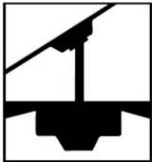
NORMAL DOWNROD INSTALLATION - If installing downrod supplied with fan, proceed to step 6.
EXTENDED DOWNROD INSTALLATION - If installing with longer downrod than supplied with fan, proceed to step 8.

natural_image
Pure mechanical cross-section diagram without any text, numbers, or symbolsNoRMAL
natural_image
Pure mechanical diagram showing a lever and pivot (no text or symbols)oPCIÓN CoN
VARILLA VERTICAL
MÁS LARGA
Place downrod assembly (I) into canopy (E), canopy cover ring (G) and coupling cover (P). Feed motor wires though the downrod assembly (I).

Loosen set screws (R) in downrod coupling (J). Insert downrod (I) into downrod coupling (J). Make sure to align hole in downrod (I) with the hole in downrod coupling (J). Install coupling cross pin (N) through coupling and downrod. Insert clamp pin (M) into cross pin until it snaps into place. Tighten set screws (R) in coupling. PROCEED TO STEP 10.

Loosen downrod ball (H) from downrod (I) by removing set screw (Q). Slide downrod ball (H) off of downrod and remove pin (O).

Re-install pin (O) into extended downrod, and slide downrod ball (H) up to the top of the downrod. Re-install set screw (Q) to secure ball to downrod. Note: Some extended downrods have a pre-drilled set-screw hole. If a pre-drilled hole is present in the extended downrod, tighten the set screw into the pre-drilled hole in the extended downrod. If no pre-drilled hole exists in the extended downrod, tighten the set screw against the downrod to secure the downrod ball. PROCEED TO STEP 6.
9
Carefully lift fan assembly onto mounting bracket (F). Rotate fan until notch on downrod ball (H) engages the ridge on the mounting bracket (F). This will allow for hands free wiring. See following step for wiring instructions.
10
Make wiring connections from the house and the fan to the remote receiver (L) as shown. Connect using wire nuts (W) (provided). Make sure that all exposed wiring is secured inside wire nuts. Refer to Point 3 of Safety Tips on page 2.
11
This remote control unit is equipped with 16 code combinations to prevent possible interference from or to other remote units. The frequency switches on your receiver (L) and transmitter (K) have been preset at the factory. Please recheck to make sure the switches on transmitter (K) and receiver (L) are set to the same position, any combination of settings will operate the fan as long as the transmitter and receiver are set to the same position.
Note: Install one 6F22 (9V) battery by removing battery cover on back of transmitter, installing battery, and replacing battery cover.
Once wiring step has been completed, slide the wired remote receiver in between the bracket (F) and the top of the downrod ball (H).
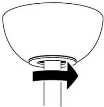
Align the keyholes on the canopy (E) with the protruding screw heads (S) from the mounting bracket (F). Lift the canopy up and rotate clockwise until the screwheads engage the keyslots fully.
The inside canopy cover ring (G) has two keyhole slots that allow it to be mounted onto the screw heads on the two protruding screws from the mounting bracket. Slide the canopy cover ring up the downrod, and allow the two protruding screw heads from the mounting bracket to go into the keyhole slots on the canopy cover ring. Once engaged, twist the canopy cover ring to lock it onto the screw heads.
Note: Some adjustment of the screws from the mounting bracket may be necessary to allow the canopy cover ring to attach to the screw heads in the appropriate manner:
- Loosening of the screw heads may be necessary to allow the canopy cover ring to fit onto the screws from the mounting bracket.
- If the canopy is still loose after installing the canopy cover ring, the canopy cover ring may need to be removed and the mounting bracket screws tightened slightly to allow a more snug fit of the canopy, when the canopy cover ring is installed.
15
natural_image
Simple line drawing of a funnel-shaped object with a black arrow pointing to its base (no text or symbols)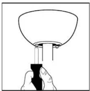
natural_image
Hand holding a tool interacting with a bowl-shaped object (no text or symbols visible)Attach blades (C) to the flywheel (B) using the blade bracket screws (T) and metal washers (V).
16
Install E12 base, max 60W bulb (X) (included).
Locate the indentations on the neck of the glass (D) and align with the protrusions from the light kit. Lift the glass up allowing the protrusions to engage the indentations on the glass, and twist the glass clockwise to lock into place.
18
natural_image
Illustration of a hand holding a screwdriver inside a circular mechanical component (no text or symbols)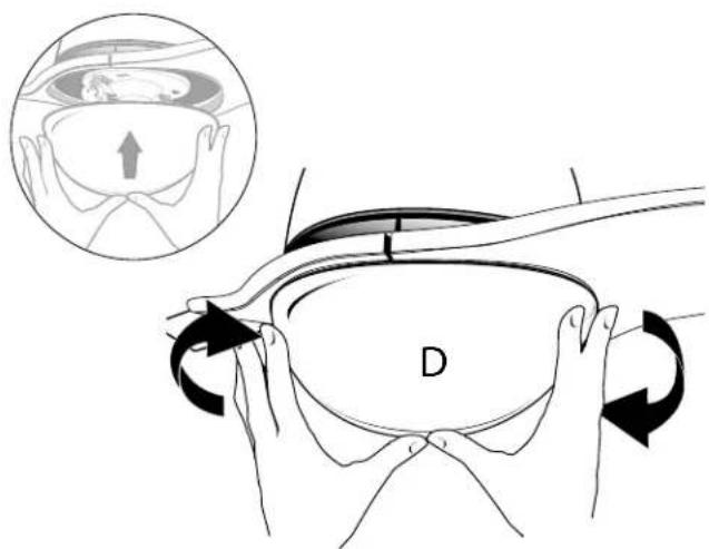
19
Mount wall bracket to the wall using screws provided.
natural_image
Diagram of a screwdriver inserted into a socket with a black arrow indicating direction (no text or symbols)20
Place the transmitter into the mounted holder.
Remote Control Operation
- Fan Control- press and release. The remote control operates the fan speed as follows: HI - high; MED - medium; LOW - low; OFF - off.
- Light On/Off - press and release light button.
- Light Dimmer - continuous pressure on the light button dims light in a continuous cycle from light to dark, or dark to light.
21
NOTICE
This 'Energy Policy Act 2005' compliant fan includes a device that limits the total wattage of its light fixture to 190 watts.
By installing a combination of light bulbs that exceeds 190 watts or if an electrical surge causes the wattage to exceed 190 watts, the light fixture will either dim the lights to 190 watts or will automatically turn off.
To restore the light levels, make sure the total wattage of the light bulbs does not exceed 190 watts and follow the applicable directions below:
For fans with Pull Chains:
Pull the light fixture's pull chain two times to reset the light fixture. If the power to your fan is controlled by a toggle wall switch, it may be necessary to turn the power off and back on at the wall switch.
For fans with Wall Controls:
Press the light button on the wall control "off" and "on" once to reset the light fixture.
For fans with Remote Controls:
If you verify the wattage and the lights do not turn on, press the light button on the remote control twice to reset the light fixture.
NOTE: If the procedures above do not reset the lights, turn off the main power source, located at the breaker panel or box, and then turn it on again.
AVISO
Speed settings for warm or cool weather depend on factors such as room size, ceiling height, number of fans and so on.
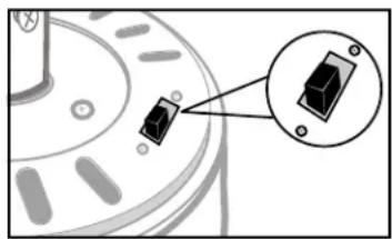
The slide switch controls direction, forward or reverse.
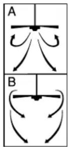
Warm weather - (Forward) Fan turns counterclockwise direction. A downward air flow creates a cooling effect as shown in illustration A. This allows you to set your air conditioner on a higher temperature setting without affecting your comfort.
Cool weather - (Reverse) Fan turns clockwise direction. An upward airflow moves warm air off the ceiling area as shown in illustration B. This allows you to set your heating unit on a lower setting without affecting your comfort. (Please however refer to point 14 in Safety Tips when operating in this position.)
NOTE: Turn off and wait for fan to stop before changing the setting of the forward/reverse slide switch.
Maintenance
- Because of the fan's natural movement, some connections may become loose.
Check the support connections, brackets, and blade attachments twice a year. Make sure they are secure. - Clean your fan periodically to help maintain its new appearance over the years. Do not use water when cleaning. This could damage the motor, or the wood, or possibly cause electrical shock.
- Use only a soft brush or lint-free cloth to avoid scratching the finish. The plating is sealed with a lacquer coating to minimize discoloration or tarnishing.
- There is no need to oil your fan. The motor has permanently lubricated bearings.
natural_image
Close-up of a mechanical component with a close-up inset showing a 3D block (no text or symbols visible)Troubleshooting Guide
| PROBLEM | Sugested Remedy |
| If fan does not start: | 1. Check main and branch circuit fuses or circuit breakers.2. Check wire connections as performed in step #11 of installation.CAUTION: Make sure main power is turned off.3. Make sure forward/reverse switch is firmly to one side or the other. Fan will not operate when switch is in the middle.4. If the fan still will not start, contact a qualified electrician. Do not attempt to troubleshoot internal electrical connections yourself. |
| If fan sounds noisy: | 1. Check all screws installed or adjusted during assembly and installation of the fan to ensure that they are properly secured.2. Some fan motors are sensitive to signals from Solid State variable speed controls.DO NOT USE a Solid State variable speed control.3. Allow “break-in” period of 24 hours. Most noises associated with a new fan will disappear after this period. |
| If fan wobbles: | 1. Check that all blades are screwed firmly into blade holders.2. Make sure that canopy and mounting bracket are tightened securely to ceiling joist.3. Make sure the set screws in the down rod coupling (under the coupling cover, refer to step 7 on page 7) are secure. |
| If light does not work: | 1. Check to see that the wire connections in step 11.2. Check for faulty light bulbs.3. If light kit will still not operate, contact a qualified electrician for assistance. |
Operación
natural_image
Close-up of a mechanical component with a close-up inset showing a small black component (no text or symbols visible)Westinghouse Lighting, Philadelphia, PA 19154-1029, U.S.A.
www.westinghouselighting.com

WESTINGHOUSE, and INNOVATION YOU CAN BE SURE OF
are trademarks of Westinghouse Electric Corporation
Used under license by Westinghouse Lighting
All rights reserved.
Made in China

Brand : WESTINGHOUSE
Model : Solana
Category : Ventilateur domestique