
CMG2V2BG - Cooker CANDY - Free user manual and instructions
Find the device manual for free CMG2V2BG CANDY in PDF.


| Product Type | Freestanding Cooker |
| Model | CMG2V2BG |
| Brand | Candy |
| Dimensions (H x W x D) | 85 cm x 60 cm x 60 cm |
| Weight | Approximately 50 kg |
| Power Supply | 220-240 V, 50/60 Hz |
| Total Power Consumption | 10.5 kW |
| Hob Type | Gas (4 burners) |
| Oven Type | Electric fan-assisted oven |
| Oven Capacity | 71 liters |
| Grill Function | Yes, with variable temperature |
| Cleaning Method | Easy-clean enamel interior |
| Child Lock | Yes |
| Automatic Shut-Off | Yes (after 12 hours) |
| Spare Parts Availability | Original Candy spare parts available |
| Energy Efficiency Class (Oven) | A |
Frequently Asked Questions - CMG2V2BG CANDY
User questions about CMG2V2BG CANDY
0 question about this device. Answer the ones you know or ask your own.
Ask a new question about this device
Download the instructions for your Cooker in PDF format for free! Find your manual CMG2V2BG - CANDY and take your electronic device back in hand. On this page are published all the documents necessary for the use of your device. CMG2V2BG by CANDY.
USER MANUAL CMG2V2BG CANDY
natural_image
Line drawing of a four-cylinder electrical heating element with six small cylindrical components on the base (no text or symbols)USER MANUAL
USER GUIDE
GB
IT
KORISNIČKI PRIRUČNIK
HR
MANUAL DE UTILIZARE
RO
PRIROČNIK ZA UPORABO
SL
ΕΓΧΕΙΡΙΔΙΟ ΧΡΗΣΗΣ
EL
Candy Hoover Group S.r.l. - Via Comolli 16, 20861 Brugherio (MB), ITALY
Dear User,
Our objective is to make this product provide you with the best output which is manufactured in our modern facilities in a careful working environment, in compliance with total quality concept.
Therefore, we suggest you to read the user manual carefully before using the product and, keep it permanently at your disposal.
Note: This user manual is prepared for more than one model. Some of the features specified in the Manual may not be available in your appliance.
All our appliances are only for domestic use, not for commercial use.
Products marked with (*) are optional.
"Conforms with the WEEE Regulations."
Contens
Important warnings 4
Electrical connection 14
Gas connection 15
Introduction of the appliance 18
Technical features 19
Installation of cooktop 21
Correct place for installation 22
Installation diagram 23
If built-in oven is placed under cooktop 24
Counter cutting sizes 25
Usage of your cooktop 26
Maintenance and cleaning 29
Troubleshooting 30
Handling rules 31
Environmentally-friendly disposal 31
Package information 31
IMPORTANT WARNINGS
- Installation and repair should always be performed by “AUTHORIZED SERVICE”. Manufacturer shall not be held responsible for operations performed by unauthorized persons.
- Please read this operating instructions carefully. Only by this way you can use the appliance safely and in a correct manner.
- The cooker should be used according to operating instructions.
- Keep children below the age of 8 and pets away when operating.
- WARNING: Fire hazard; do not store the materials on the cooking surface.
- WARNING: The appliance and its accessible parts are hot during operation.
- Setting conditions of this device are specified on the label. (Or on the data plate)
- The accessible parts may be hot when the grill is used. Small children should be kept away.
- WARNING: This appliance is intended for cooking. It should not be used for other purposes like heating a room.
- To clean the appliance, do not use steam cleaners.
-
NEVER try to put out the fire with water. Only shut down the device circuit and then cover the flame with a cover or a fire blanket.
-
Children under 8 years of age should be kept away, if they cannot be monitored continuously.
- Touching the heating elements should be avoided.
- CAUTION: Cooking process shall be supervised. Cooking process shall always be supervised.
- The appliance is not suitable for use with an external timer or a separate remote control system.
- This device can be used by children over 8 years of age, people with physical, hearing or mental challenges or people with lack of experience or knowledge; as long as control is ensured or information is provided regarding the dangers.
- This device has been designed for household use only.
- Children must not play with the appliance. Cleaning or user maintenance of the appliance shall not be performed by children unless they are older than 8 years and supervised by adults.
- Keep the appliance and its power cord away from children less than 8 years old.
- Put curtains, tulles, paper or any flammable (ignitable) material away from the appliance before starting to use the appliance. Do not put ignitable or flammable materials on or in the appliance.
- Keep the ventilation channels open.
- Do not heat closed cans and glass jars. The pressure may lead jars to explode.
GB
- Do not use the product in states like medicated and/or under influence of alcohol which may affect your ability of judgement.
- After each use, check if the unit is turned off.
- Be careful when using alcohol in your foods. Alcohol will evaporate at high temperatures and may catch fire to cause a fire if it comes in contact with hot surfaces.
- If the appliance is faulty or has a visible damage, do not operate the appliance.
- Do not put objects that children may reach on the appliance.
- The packaging materials are dangerous for children. Keep packaging materials away from the reach of children.
- Cooker supply can be disconnected during any construction work at home. After completing the work, re-connecting the cooker shall be done by authorized service.
- Do not place metal utensils such as knife, fork, spoon on the surface of the appliance, since they will get hot.
- To prevent overheating, the appliance should not be installed behind of a decorative cover.
-
Turn off the appliance before removing the safeguards. After cleaning, install the safeguards according to instructions.
-
Cable fixing point shall be protected.
- CAUTION: If the glass of the stove is broken, turn off any heating element immediately and disconnect the appliance from power source, do not touch the surface of the appliance and do not use the appliance.
- User should not handle the cooker by himself.
- Use shall be careful when cleaning gas burners. It may cause personal injuries.
- Since the hob is hot during cooking or right after cooking, scalding may occur due to extreme temperature and steam.
- When not turning of the cooker during cooking, user can touch hot surfaces causing burns.
- If heavier loads are places on the cooker, these loads can trip over. It may cause personal injuries.
- Allow disconnection of the appliance after installation, by accessible plug or a switch in the fixed wiring, unless.
Electrical Safety
- Plug the appliance in a grounded socket protected by a fuse conforming to the values specified in the technical specifications chart.
- Have an authorized electrician set grounding equipment. Our company shall not be responsible for the damages that shall be incurred due to using the product without grounding according to local regulations.
- WARNING: If the surface is cracked, turn off the appliance to avoid risk of electric shock.
- Never wash the appliance by spraying or pouring water on it. There is a risk of electrocution.
- Do not touch the plug with wet hands. Do not pull the cord to plug off, always hold the plug.
- Unplug the unit during installation, maintenance, cleaning and repair.
- Make sure the plug is inserted firmly into wall socket to avoid sparks.
- If the power supply cord (the cord with plug) is damaged, this cord shall be replaced by the manufacturer or its service agent or an equally qualified personnel to prevent a hazardous situation.
- Do not use cut or damaged cords or extension cords other than the original cord.
-
Do not use steam cleaners for cleaning the appliance, otherwise electric shock may occur.
-
Make sure there is no liquid or humidity in the outlet where the product plug is installed.
- An omnipolar switch capable to disconnect power supply is required for installation. Disconnection from power supply shall be provided with a switch or an integrated fuse installed on fixed power supply according to building code.
- The power supply cord (the cord with plug) shall not contact the hot parts of the appliance.
- Unplug the unit during installation, maintenance, cleaning and repair.
- Appliance is equipped with a type "Y" cord cable.
- The circuit breaker switches of the cooker shall be placed so that end user can reach them when the cooker is installed.
- Fixed connections shall be connected to a power supply enabling omnipolar disconnection. For appliances with over voltage category below III, disconnection device shall be connected to fixed power supply according to wiring code.
- Do not remove ignition switches from the appliance. Otherwise, live electric cables can be accessed. It may cause an electric shock.
Gas Safety
- This appliance is not connected to burning products evacuation apparatus. This appliance must be connected and installed according to the installation regulations in force. Conditions regarding ventilation must be considered.
- When a gas cooking appliance is used; humidity, heat and burning products are generated in the room. First of all, make sure the kitchen is well ventilated when operating the appliance and maintain natural ventilation openings or install a mechanical ventilation equipment.
- After using the appliance heavily for en extended period of time, additional ventilation may be required. For example open a window or adjust a higher speed for mechanical ventilation, if any.
- This appliance must be used only in well ventilated locations in accordance with the regulations in force. Please read the manual before installing or using this product.
- Before positioning the appliance, make sure local network conditions (gas type and gas pressure) meets appliance requirements.
-
The mechanism cannot be run for longer than 15 seconds. If the burner is not on after 15 seconds, stop the mechanism and wait for at least one minute before trying to ignite the burner again.
-
All kinds of operations to be performed on gas installation must be performed by authorized and competent people.
- This appliance is adjusted for natural gas (NG). If you have to use your product with a different gas type, you have to apply to authorized service for the conversion.
- For proper operation, hood, gas pipe and clamp should be replaced periodically accordint to manufacturer recommendations and when required.
- Gas should burn well in gas products. Well burning gas can be understood from blue flame and continuous burning. If gas does not burn sufficiently, carbon monoxide (CO) can be generated. Carbon monoxide is a colourless, odourless and very toxic gas; even small amounts have lethal effect.
- Ask your local gas supplies about the phone numbers for emergencies related to gas and the measures to be taken upon gas odour is detected.
What To Do When Gas Odour Is Detected
- Do not use naked flame, and do not smoke.
- Do not operate any electrical switch.
(For example: lamp switch or doorbell) - Do not use telephone or mobile phone.
- Open the doors and windows.
- Close all valves on the appliances that utilize gas and the gas counters.
- Check all hoses and their connections against leaks. If you still smell gas, leave the house and warn your neighbours.
- Call fire brigade from a telephone outside the home.
- Do not enter into the house until authorities clarify it is safe.
Intended Use
- This product is designed for home use. Commercial use of the appliance is not permitted.
- This appliance may only be used for cooking purposes. It shall not be used for other purposes like heating a room.
- The manufacturer assumes no responsibility for any damage due to misuse or mishandling.
- Operational life of the product you have purchased is 10 years. This is the period for which the spare parts required for the operation of this product as defined is provided by the manufacturer.
Methods for Protecting Ceramic Glass Cooking Surface
Ceramic glass surface is unbreakable and scratch resistant to a certain degree. However, to avoid any damage, please do the following:
- Never pour cold water on hot cookers.
- Do not stand on a ceramic glass plate.
- Sudden pressure, for example, the effect of a falling salt shaker may be critical. So, do not place such objects on a place above the hobs.
- After each use, make sure that the base of the cooking pot and surfaces of cooking zones are clean and dry.
- Do not peel vegetables on the hob surfaces. Sand grains falling from the vegetables may scratch the ceramic glass plate.
- Do not lay flammable materials such as cardboard or plastic on the oven. Objects such as tin, zinc, or aluminium (as well as aluminium foils or empty coffee pots) may melt on hot cooking surfaces and thus cause damage.
- Take care not to let sugary foods or fruit juices contact the hot cooking zones. The ceramic glass surface may be stained by these.
Electrical Connection
- Setting conditions of this appliance is indicated in tag or data plate.
- Your appliance should be plugged in a fuse appropriate for electric power. If necessary, it is recommended that installation is done by authorized service.
- Your appliance is configured in accordance with electrical supply of 220-240V 50/60Hz.
- If main electrical network is different from these values, contact with your authorized service.
- Electrical connections of your appliance should only be made to the fuses having suitably wired grounding (grounded) system. If no convenient fuse is available in the place where your appliance is to be installed, contact with authorized service immediately. Manufacturing firm is not responsible definitely for the damages that fuses whose grounding is not made and connected to the appliance can cause.
- Plug of the appliance should be close to be accessed easily to the fuse whose grounding is made without use of extension cord.
- Do not allow contacting the power cable of your appliance with hot regions. Similarly, keep away it from sharp edges and corners.
- If feeder cord is damaged, this cord should be replaced either by manufacturer or its service agency or same degree qualified personnel in order to hinder a dangerous situation.
- Wrong electrical connection may give damage to the appliance. In this case, your appliance will remain out of guarantee scope. Electrical connection of your appliance should be done by authorized service.
Electrical connection scheme
Get electrical connection of your appliance done to authorized person in line with the following scheme.

Gas Connection
WARNING: Before starting any work related with gas installation, turn off gas supply. Risk of explosion.
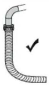
- Connect your appliance to gas cock from the shortest way and in a manner to prevent any leakage. For safety, the hose used should be maximum 125 cm and minimum 40 cm.
- While making gas leakage control; never use lighter, match, glowing cigarette or similar inflammable matter.
- Apply soap bubble on connection point. If any leak/leakage exists, foaming will occur on soaped region.
- If the cooktop is to be mounted on a cabinet or openable drawer, a heat protection panel having 15 mm minimum opening should be mounted under the cooktop.
For LPG connection;
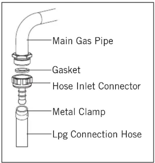
- For LPG (cylinder) connection, affix metal clamp on the hose coming from LPG cylinder. Affix an edge of the hose on hose inlet connector behind the appliance by pushing to end through heating the hose in boiled water. Afterward, bring the clamp towards end section of the hose and tighten it with screwdriver. The gasket and hose inlet connector required for connection is as the picture shown below.
WARNING: The regulator to be affixed on LPG cylinder should have 300 mmSS feature.
GB
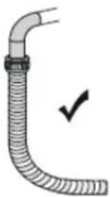
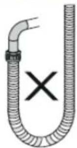
WARNING: Gas hose and electric connection of the appliance should not pass next to hot areas such as back of the appliance. Gas hose should be connected by making wide angle turns against breaking possibility. Movement of appliance whose gas connection is made may cause gas leakage.

For natural gas connection;

WARNING: Natural gas connection should be done by authorized service.
For natural gas connection, place gasket in the nut at the edge of natural gas connection hose. To install the hose on main gas pipe, turn the nut. Complete the connection by making gas leakage control.
Transformation from natural gas to LPG and from LPG to natural gas
- Turn off gas and electricity of the cooktop. If your cooktop is hot, wait for cooling down.
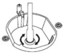
- For injector change, use a screwdriver whose edge is as the figure 1.
- As seen in figure 2, demount burner lid and burner of the cooktop and ensure visibility of injector.
- Remove injector by turning as shown in figure 3 with screwdriver and replace it with a new one.

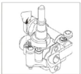
- After that, detach control switches of the cooktop. Make setting by turning the screw in the middle of gas cocks with a small screwdriver in the manner shown in the following picture. To adjust flow rate screw, use a screwdriver having suitable dimension. For LPG, turn the screw clockwise. For natural gas, turn the screw one time counter clockwise. At low position, length of normal flame should be 6-7 mm. For the last control, check out whether flame is open or closed.
Setting of your appliance may differ according to the type of gas cock used.

natural_image
Diagram of a circular mechanical component with two cylindrical parts and a handle, no text or symbols present
natural_image
Technical line drawing of a mechanical assembly with no visible text or symbolsFigure 4 Figure 5
Ventilation Of Room
The air needed for burning is received from room air and the gases emitted are given directly in room. For safe operation of your product, good room ventilation is a precondition. If no window or room to be utilized for room ventilation is available, additional ventilation should be installed. However, room has a door opening outside, it is no needed to vent holes.
| Room size Ventilating opening | |
| Smaller than 5 m^3 min. 100 cm^2 | |
| Between 5 m^3 - 10 m^3 min. 50 cm^2 | |
| Bigger than 10 m^3 no need | |
| In basement or cellar min. 65 cm^2 |
INTRODUCTION OF THE APPLIANCE

natural_image
Technical line drawing of a mechanical component with a central shaft and flange (no text or symbols)456

natural_image
Technical line drawing of a mechanical component with a central shaft and circular base (no text or symbols)
natural_image
Technical line drawing of a mechanical component with three arms and a central shaft (no text or symbols)
natural_image
Technical line drawing of a mechanical component with concentric rings and mounting brackets (no text or symbols)7
8

9

10

11
natural_image
Simple line drawing of a decorative frame with a handle and circular base (no text or symbols)12

natural_image
Isometric line drawing of a mechanical component with symmetrical slots and a central cross (no text or symbols)
natural_image
Pure technical line drawing of a rectangular frame with internal slots and no text or symbols14
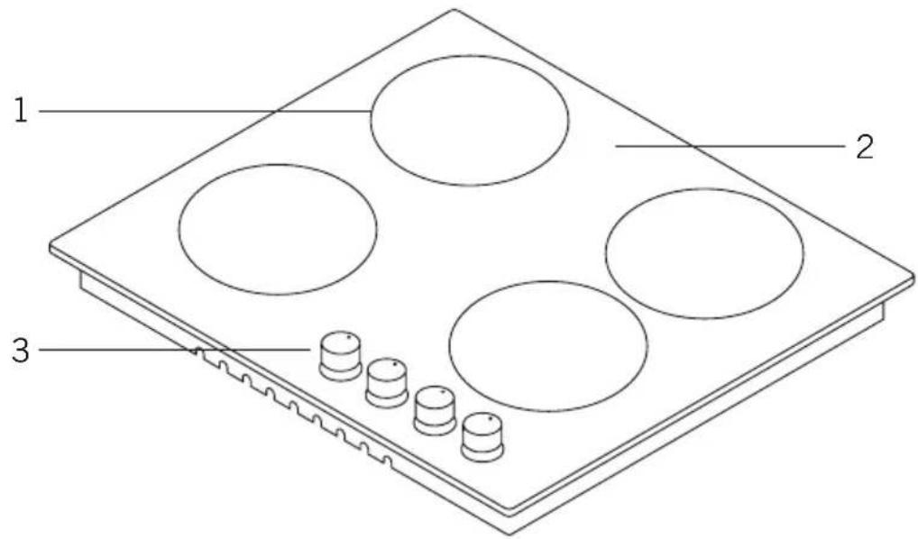
- Burner positions
- Glass or metal surface
- Control buttons
- Small burner
- Medium burner
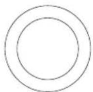
- Large burner
-
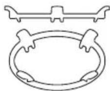
Wok burner *
-
Ceramic heater (120 mm / 180 mm) *
- Ceramic heater (180 mm or 140 mm) *
- Ceramic heater (140 / 250 mm) *
- Coffee adaptor *
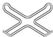
- Wok burner adaptor *
- Cast grill
- Enamel grill
Technical features
| Burner Specifications | G20,20 mbar G25,25 mbar | G20,25 mbar G20,13 mbar | |||||
| Gas natural Gas natural Gas natural | |||||||
| Wok burner (3,5) | Injector | 1,40 | mm 1,28 | mm | 1,60 mm | ||
| Gas flow | 0,333 m^3 /h | 0,333 m^3 /h | 0,333 m^3 /h | ||||
| Power 3 | 50 kW 3,5 | 50 kW 3,5 | 0 kW | ||||
| Wok burner (2,5) | Injector | 1,15 mm 1,06 mm 1,35 mm | |||||
| Gas flow | 0,243 m^3 /h | 0,243 m^3 /h | 0,243 m^3 /h | ||||
| Power 2 | 50 kW 2,5 | 50 kW 2,5 | 0 kW | ||||
| Rapid burner | Injector | 1,15 mm 1,10 mm 1,45 mm | |||||
| Gas flow | 0,276 | m^3 /h | 0,276 | m^3 /h | 0,276 | m^3 /h | |
| Power 2 | 90 kW 2,9 | 90 kW 2,9 | 0 kW | ||||
| Semi-Rapid burner | Injector | 0,97 mm | 0,92 mm | 1,10 mm | |||
| Gas flow | 0,162 m^3 /h | 0,162 m^3 /h | 0,162 m^3 /h | ||||
| Power | 1,70 | kW | 1,70 | kW | 1,70 | kW | |
| Auxiliary burner | Injector | 0,72 mm | 0,70 mm | 0,85 mm | |||
| Gas flow | 0,96 m^3 /h | 0,96 m^3 /h | 0,96 m^3 /h | ||||
| Power 0 | 95 kW 0,95 kW 0,95 kW | ||||||
| Burner Specifications | G30,28-30 mbar G31,37 mbar | G30,50 mbar G30,37 mbar | |||||
| LPG LPG LPG | |||||||
| Wok burner (3,5) | Injector | 0,96 mm | 0,76 mm | 0,96 mm | |||
| Gas flow | 254 g/h | 254 g/h | 254 g/h | ||||
| Power 3 | 50 kW | 3,50 kW | 3,50 kW | ||||
| Wok burner (2,5) | Injector | 0,82 mm | 0,73 mm | 0,78 mm | |||
| Gas flow | 182 g/h | 182 g/h | 182 g/h | ||||
| Power 2 | 50 kW | 2,50 kW | 2,50 kW | ||||
| Rapid burner | Injector | 0,85 mm | 0,75 mm | 0,85 mm | |||
| Gas flow | 211 g/h | 211 g/h | 211 g/h | ||||
| Power 2 | 90 kW | 2,90 kW | 2,90 kW | ||||
| Semi-Rapid burner | Injector | 0,65 mm | 0,60 mm | 0,65 mm | |||
| Gas flow | 124 g/h | 124 g/h | 124 g/h | ||||
| Power | 1,70 | kW | 1,70 | kW | 1,70 | ||
| Auxiliary burner | Injector | 0,50 mm | 0,43 mm | 0,50 mm | |||
| Gas flow | 69 g/h | 69 g/h | 69 g/h | ||||
| Power 0 | 95 kW | 0,95 kW | 0,95 kW | ||||
| 180 mm ceramic heater | 1800 W | ||||||
| 140 mm ceramic heater | 1200 W | ||||||
| 120 / 180 mm ceramic heater | 1700 W | ||||||
| 140 / 250 mm ceramic heater | 1800 W | ||||||
| Supply voltage | 220-240 V 50/60 Hz. | ||||||
WARNING: Diameter values written on the injector are specified without a comma. For example; The diameter of 1,70 mm is specified as 170 on the injector.
WARNING: For the modification to be done by authorized service, this table should be considered. Manufacturer may not be held responsible for any problems rising because of any faulty modification.
WARNING: In order to increase the product quality, the technical specifications may be changed without prior notice.
WARNING: The values provided with the appliance or its accompanying documents are laboratory readings in accordance with the respective standards. These values may differ depending on the use and ambient conditions.
INSTALLATION OF COOKTOP
Check if the electrical installation is proper to bring the appliance in operating condition. If electricity installation is not suitable, call an electrician and plumber to arrange the utilities as necessary. Manufacturer shall not be held responsible for damages caused by operations performed by unauthorized persons.
WARNING: It is customer's responsibility to prepare the location the product shall be placed on and also to have the electrical installation prepared.
WARNING: The rules in local standards about electrical installations shall be followed during product installation.
WARNING: Check for any damage on the appliance before installing it. Do not have the product installed if it is damaged. Damaged products cause a risk for your safety.
Correct Place For Installation
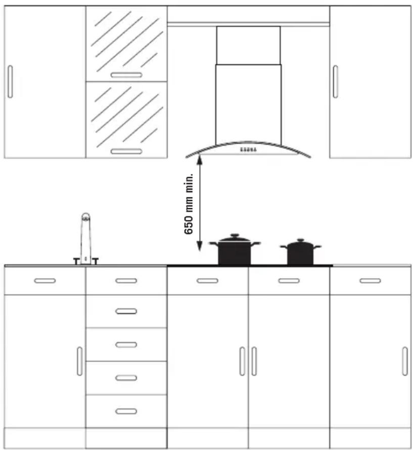
Product is designed in accordance with the kitchen counters supplied from market. A safe distance should be left between the product and kitchen walls and furniture. If hood/aspirator will be installed over your appliance, obey to the recommendation of hood / aspirator manufacturer for assembly height. (min. 65 cm) The gap that cooktop is to be placed on the counter should be cut in line with cooktop installation dimensions.
For installation of the product, the rules specified in local standards related to electricity should be complied.
GB
Installation
- Detach the burners, burner hoods and grills from the product.
- Turn the cooktop down and place on smooth ground.
- In order to prevent entrance of foreign substances and liquids between cooktop and counter, apply the paste given in package to the sides of lower guard of counter. For corners, curl paste and increase curls till filling corner gaps.
- Turn cooktop again and align with and place on counter.
- Fasten up your cooktop on counter by using the clamp and screws supplied.
Installation Diagram


natural_image
Technical line drawings of a heating appliance assembly, showing top-down and side-view views (no text or symbols)
natural_image
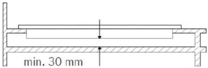
Pure structural diagram of a beam with supports and a central span (no text or symbols)- When product is mounted on a drawer, if it is possible to touch lower side of product, this section should be separated with a wooden shelf.
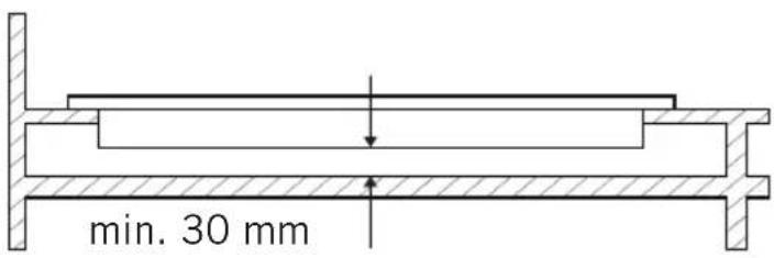
-
While mounting cooktop on a closet, as shown in the figure above, in order to separate between closet and cooktop, a shelf should be mounted. If it is mounted on a built-in oven, there is no need to do that.
-
If your cooktop will be mounted next to right or left wall, the minimum distance between wall and cooktop should be 50 mm.
If Built-In Oven Is Placed Under Cooktop

-
Cooktop
-
Hose
-
Oven
Gas pipe should be affixed in a way not to touch the oven below, sharp edges and corners, not to be pulled in a manner to be twisted and strained. Make gas connection from right part of the cooktop, fasten the hose by use of clamp.
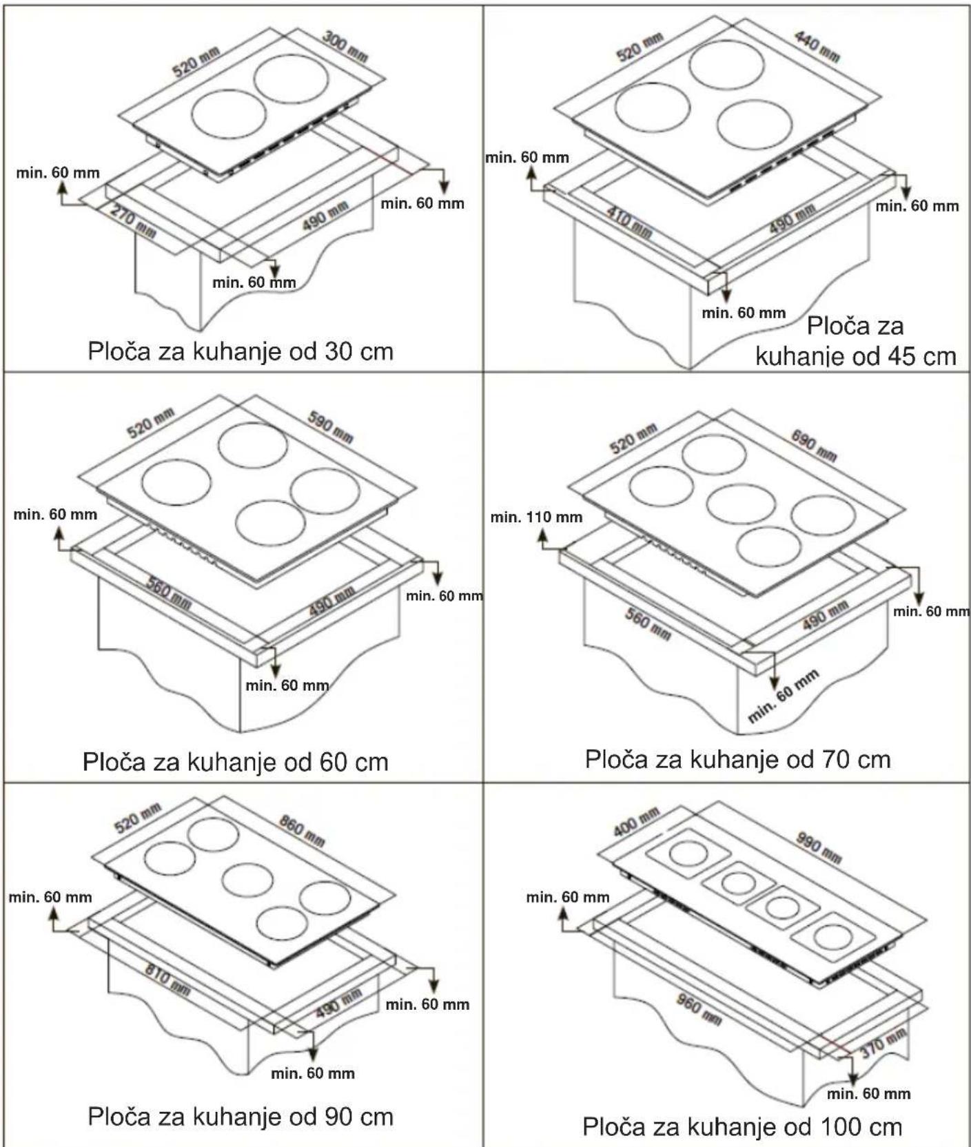
Counter Cut-Off Dimensions
Pay attention to the drawings and dimensions given below while making cooktop installation and adjusting counter cutting sizes.

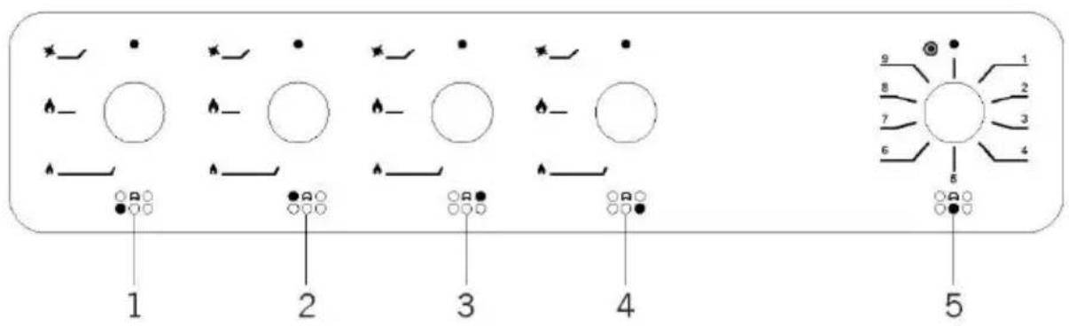
CONTROL PANEL
Cooktop Panel Visual Of 90 cm

- Front left burner
- Rear left burner
- Rear right burner
- Front right burner
- Ceramic heater
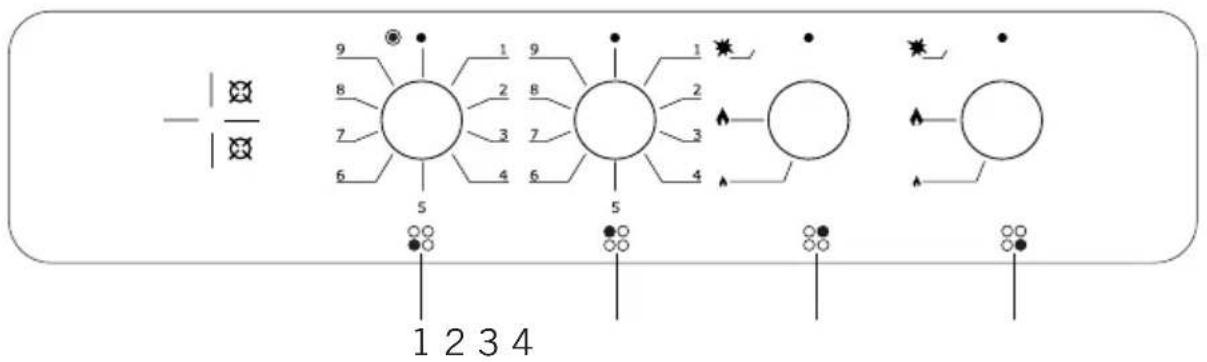
Cooktop Panel Visual Of 60 cm
flowchart
graph TD
    A["Node 1"] --> B["Node 2"]
    B --> C["Node 3"]
    C --> D["Node 4"]
    D --> E["Node 5"]
    F["Node 6"] --> G["Node 7"]
    G --> H["Node 8"]
    H --> I["Node 9"]
    J["Node 10"] --> K["Node 11"]
    K --> L["Node 12"]
    M["Node 13"] --> N["Node 14"]
    N --> O["Node 15"]
    P["Node 16"] --> Q["Node 17"]
    Q --> R["Node 18"]
    S["Node 19"] --> T["Node 20"]
    U["Node 21"] --> V["Node 22"]
    W["Node 23"] --> X["Node 24"]
- Front left ceramic heater
- Rear left ceramic heater
- Rear right burner
- Front right burner
WARNING: The control panels above is only for illustration purposes. Consider the control panel on your device.
USAGE OF YOUR COOKTOP
- Before starting to use your cooktop, be sure burner hoods are at correct position. Correct placement of burner hoods are shown in the following figure.

natural_image
Diagram of a mechanical device with a circular component and a cross symbol, labeled 'Figure 7' (no readable text or symbols)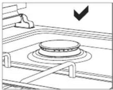
natural_image
Diagram of a mechanical component with concentric rings and a downward arrow indicator (no text or symbols)Figure 6 Figure 7
- Gas cocks have a special locking mechanism. Therefore, to operate cooktop zone, press button by pushing ahead and while opening or closing the cock, hold down the button.
- Closed
Fully open
Half open
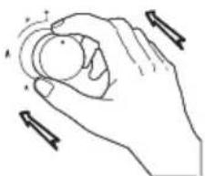
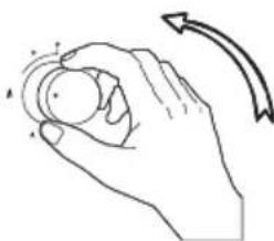
- For automatic igniting models, igniting is realized via electricity. Therefore, before operating appliance, be sure that appliance has electric connection. Igniting for these models is as follows.

Cooktop cock is at closed position.
natural_image
Line drawing of a hand holding a circular object with directional arrows indicating motion (no text or symbols)To ignite cooktop, firstly press the button towards ahead.

natural_image
Line drawing of a hand holding a circular object with motion arrows indicating rotation (no text or symbols)While holding down the button, lighter steps in and starts to ignition.
natural_image
Simple line drawing of a hand holding a circular object with motion arrows indicating rotation (no text or symbols)By turning the button left while holding down, you can provide ignition at flame length you want.
- Pay attention that cooktop grills are placed on cooktop table completely. In case of failure about this matter can cause pouring of the materials to be put on that.
-
For the models having gas putting out safety, following realizing ignition procedure according to the guidelines above, wait for 5-10 seconds by pushing button ahead without keeping your hands off. Safety mechanism will step in this duration and ensures operation of the cooktop. With regard to gas putting out appliance, gas cock cuts the gas going to cooktop zone in case of putting out of cooktop flame due to any reason.
-
Flame cut-off safety device (FFD); operates instantly when safety mechanism activates due to overflown liquid over upper hobs.

- While using coffee pot apparatus supplied along with the cooktop, be sure that foots of apparatus are placed on cooktop grill exactly and remain on cooktop zone in centred way. Use the apparatus only on small burner.
- While utilizing gas cooktops, use saucepan, placed on cooktop surface as far as possible. Thanks to that, you can save energy. In the following table, cooking pot diameters recommended to be used as per burners are given. Characteristic of Wok cooktop zone is to cook quickly.
- Ensure that the grates are fully seated on the cooktop plate. If the grate is not properly seated, this may cause spillage of materials placed on it.
- Place the pots and pans so that their handles are not placed above the hobs to prevent heating of the handles.
- Place suitable amount of food to the pots and pans. Thus, you may prevent overflowing of meals and avoid unnecessary cleaning.
- The size of the container and the gas flame shall match each other. Set gas flames so that they do not extend further than the base of the container.
- Do not use containers that are unstable and that may be easily tipped over on the cooktop.
- Do not put empty pots and pans on the hobs with their flames on.
- Always turn off the hobs after each use.
- Do not put containers that may be affected by heat on the product.
- Do not operate the hobs without any pots and pans placed on them.
- Do not place the lids of the pots and pans on the hobs.
- When you want to put the pot on another hob, take the pot up and place it again instead of sliding it.
- Keep the lid of container you use for heating oil open.
- Do not put oil with a volume more than one third of the pan. Do not leave the oil unattended when the oil is being heated. Extremely hot oils may cause fire.
- Use pots and pans with machined bases only. Sharp edges cause scratches on the surface.
- Do not use aluminium pots and pans. Aluminium cause damages to the hob surface.
GB
Wok Burner \*

natural_image
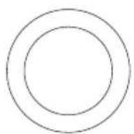
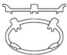
Technical line drawing of a mechanical component with concentric rings and mounting brackets (no text or symbols)As it possesses double ring flame system, it gives homogenous heat distribution at the bottom of cooking pot at high temperature. It is ideal for short term and high temperature cooking. When you want to use regular cooking pot on wok burner, it is necessary that you remove wok cooking pot carrier from cooktop.
Using The Ceramic Hobs
Turning the ceramic hobs on
Knobs for the relevant hobs shall be used to turn the ceramic hobs on. Set the hob knob to the desired position to achieve the required cooking level.
Turning the ceramic hobs off
Turn the relevant hob knob to off (●) position.
Pot Sizes
Recommended pot diameters to be used are provided in the following tables.
| Glass hobs 60 cm control front Metal ho bbs 90 cm control front | |
| Small burner 12-18 cm Small burner 12-18 cm | |
| Middle burner 18-20 cm Middle burner 18-22 cm | |
| Big burner 22-24 cm Big burner 22-26 cm | |
| Wok burner 24-26 cm Wok burner 26-32 cm |
WARNING: Cooking pot to be used with products should have minimum 120 mm diameter.

natural_image
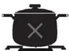
Silhouette of a cooking pot with steam rising, marked with an 'X' on the pot (no text or symbols)Splashes and overflow may cause damage to the cooktop surface and fire.

Do not use containers with convex or concave bases.

If the diameter of the pot is smaller than the diameter of the hob, this shall waste energy.

natural_image
Silhouette of a cooking pot with a checkmark inside, no text or symbols presentUse pots and pans with flat bases only.
MAINTENANCE AND CLEANING
Before starting to maintenance or cleaning, firstly unplug the plug supplying electricity to cooktop and turn off gas valve. If cooktop is hot, wait for cooling down.
- For the purpose that your cooktop has long and economic life, regular cleaning and maintenance should be performed on your cooktop.
- Do not clean your cooktop with scratching tools such as bristle brush, wire wool or knife. Do not use abrasive, scratching, acid materials or detergent.
- Following mopping parts of your cooktop with soapy cloth, rinse it, later rinse well with a soft cloth.
- Clean glass surfaces with special glass cleaning substances. As scratching of glass surfaces leads to breaking, while cleaning glass surfaces, do not use abrasive cleaners or sharp metal scrapers.
- Do not clean your cooktop with steamy cleaners.
- Clean channels and lids of cooktop zones with soapy water and clean gas channels with a brush.
- In the course of cleaning your cooktop, never use flammable materials such as acid, thinner and gas.
- Do not wash plastic and aluminium parts of your cooktop in dishwasher.
- Clean vinegar, lemon, salt, coke and similar acid and alkaline containing substances poured on your cooktop immediately.
- In time, cooktop buttons turns hard or never turn any more, in such circumstances, it may be necessary that buttons are changed. The change should only be done by authorized service.
TROUBLESHOOTING
You may solve the problems you may encounter with your product by checking the following points before calling the technical service.
Check Points
In case you experience a problem about the cooker, first check the table below and try out the suggestions.
| Problem Possible | cause Remedy | |
| No Ignition | No sparks. Check power supply. | |
| Cooker cover is not fitted properly. Fit the | cover properly. | |
| Gas supply is closed. Fully open gas supply. | ||
| Not Proper Ignition | Gas supply not fully open. Fully open gas supply. | |
| Cooker cover is not fitted properly. Fit the | cover properly. | |
| Ignition plug is clogged with foreign materials. | Wipe off foreign materials with a cloth. | |
| Hobs are wet. Carefully dry the hobs. | ||
| Flame spreader holes are clogged. Clear | the flame spreader. | |
| Noise coming when burning or during ignition | Cooker cover is not fitted properly. Fit the | cover properly. |
| Flame turns off during operation | Flame observer device is clogged by foreign material. | Clean flame observer device. |
| Overflow food turns off the flame. | Switch off the hob. Wait for one minute and ignite again. | |
| A strong air flow turns off the flame. | Please check related hob and check the cooking area for air flows, for example, from an open window. Wait for one minute and ignite again. | |
| Yellow flame | Flame spreader holes are clogged. Clear | the flame spreader. |
| Different gas is being used. Check the gas being used. | ||
| Unstable flame | Cooker cover is not fitted properly. | Fit the cover properly. |
| Gas odour | Hob spout left open. Check if any hob spouts are left open. | |
| Leakage from connection of gas cylinder to cooker. | Make sure connections are leak-proof. | |
| Lighter not operating. | Tips or body of ignition plugs are clogged. | Clean tips or body of ignition plugs of gas burners. |
| Gas burner pipes are clogged. Clean gas | burner pipes. |
HANDLING RULES
- Carry out the movement and transportation in the original packaging.
- Pay maximum attention to the appliance while loading/unloading and handling.
- Make sure that the packaging is securely closed during handling and transportation.
- Protect from external factors (such as humidity, water, etc.) that may damage the packaging.
- Be careful not to damage the appliance due to bumps, crashes, drops, etc. while handling and transporting and not to break or deform it during operation.
ENVIRONMENTALLY-FRIENDLY DISPOSAL

natural_image
Symbol of a trash bin crossed with a diagonal line, no text or numbers presentDispose of packaging in an environmentally-friendly manner.
This appliance is labelled in accordance with European Directive 2012/19/EU concerning used electrical and electronic appliances (waste electrical and electronic equipment - WEEE). The guideline determines the framework for the return and recycling of used appliances as applicable throughout to the EU.
PACKAGE INFORMATION
Packaging materials of the product are manufactured from recyclable materials in accordance with our National Environment Regulations. Do not dispose of the packaging materials together with the domestic orotherwastes. Takethemtothepackagingmaterialcollectionpoints designated by the local authorities.
Gentile cliente,
natural_image
Technical line drawing of a mechanical component with no visible text or symbolsFigura 2
natural_image
Technical line drawing of a mechanical component with rotating shaft and base (no text or symbols)Figura 3
IT
natural_image
Simple line drawing of a circular mechanical component with two cylindrical parts and a handle (no text or symbols)
natural_image
Technical line drawing of a mechanical assembly with no visible text or symbolsFigura 4 Figura 5
natural_image
Technical line drawing of a mechanical component with a central shaft and flange (no text or symbols)456

natural_image
Technical line drawing of a mechanical component with concentric rings and a central shaft (no text or symbols)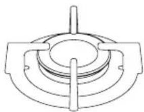
natural_image
Technical line drawing of a mechanical component with concentric rings and a central shaft (no text or symbols)
natural_image
Technical line drawing of a mechanical component with concentric rings and central shaft (no text or symbols)7
8

9

10
11
natural_image
Simple line drawing of a decorative frame with a horizontal bar and circular base (no text or symbols)12

natural_image
Isometric line drawing of a mechanical or architectural component with symmetrical slots and protrusions (no text or symbols)
natural_image
Technical line drawing of a rectangular frame with internal channels and mounting brackets (no text or symbols)14
natural_image
Technical line drawings of a heating appliance assembly, showing front, top, and side views with no visible text or symbols.
natural_image
Pure diagram of a horizontal beam with two supports at both ends, no text or symbols presentIT
natural_image
Diagram of a kitchen sink with a valve and a cross symbol, no readable text or labels present
natural_image
Diagram of a gas stove interior with a circular vent and heating element (no text or symbols)Figura 6 Figura 7
natural_image
Line drawing of a hand holding a circular object with directional arrows indicating motion (no text or symbols)natural_image
Hand holding a circular object with motion arrows indicating rotation (no text or symbols)natural_image
Line drawing of a hand holding a circular object with motion arrows indicating rotation (no text or symbols)natural_image
Technical line drawing of a mechanical component with concentric rings and mounting brackets (no text or symbols)natural_image
Silhouette of a cooking pot with steam rising from it, marked with an 'X' symbol (no text or labels)natural_image
Silhouette of a cooking pot with a checkmark inside, no text or symbols presentnatural_image
Symbol of a trash bin crossed with a diagonal line, no text or numbers presentnatural_image
U-shaped pipe with a checkmark indicating a specific section (no text or symbols present)Točno

natural_image
Diagram of a U-shaped tube with a bulbous end and a cross symbol inside (no text or labels)Netočno
natural_image
Illustration of a coiled tube with a checkmark indicating selection (no text or symbols present)Točno

Točno
natural_image
Technical line drawing of a mechanical component with no visible text or symbolsSlika 2

natural_image
Mechanical component diagram showing a rotating shaft and housing with no visible text or symbolsSlika 3
- Nakon toga odvojite upravljačke sklopke ploče za kuhanje. Podesite okretanjem vijka na sredini plinskih slavina malim odvijačem na način prikazan na sljedećoj slici. Za podešavanje vijka za brzinu protoka upotrijebite odvijač prikladnih dimenzija. Za LPG okrećite vijak udesno. Za prirodni plin okrenite vijak jednom ulijevo. Na niskom položaju duljina normalnog plamena treba biti 6-7 mm. Za zadnju kontrolu provjerite je li plamen otvoren ili zatvoren.
Podešavanje uređaja može se razlikovati ovisno o vrsti plinske slavine koja se koristi.

natural_image
Simple line drawing of a circular container with two cylindrical objects and a handle (no text or symbols)Slika 4
natural_image
Technical line drawing of a mechanical assembly (no text or symbols visible)Slika 5
natural_image
Technical line drawing of a mechanical component with a central shaft and circular base (no text or symbols)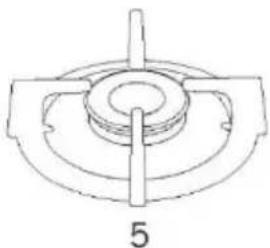
natural_image
Technical line drawing of a mechanical component with a central shaft and circular base (no text or symbols)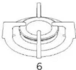
natural_image
Technical line drawing of a mechanical component with concentric rings and a central shaft (no text or symbols)
natural_image
Technical line drawing of a mechanical component with concentric rings and a central shaft (no text or symbols)
natural_image
Two concentric circles with the number 8 below (no text or symbols within the circles)
natural_image
Simple black circle outline with the number 9 below it (no text or symbols inside)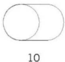
natural_image
Simple geometric diagram showing a circle partially overlapping a larger circle, labeled with the number 10 below (no text or symbols within the shapes)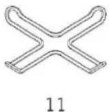
natural_image
Simple line drawing of a four-way X-shaped pipe or tube structure (no text or symbols)
natural_image
Simple line drawing of a circular object with two protruding arms above it, labeled '12' below (no text or symbols on the object itself)
natural_image
Isometric line drawing of a 3D maze-like structure with no text or symbols
natural_image
Technical line drawing of a rectangular frame with internal channels and a label '14' (no text or symbols on the diagram itself)- Položaji plamenika
- Staklena ili metalna površina
- Upravljačke tipke
- Mali plamenik
- Srednji plamenik
- Veliki plamenik
-
Plamenik za wok*
-
Keramički grijač (120 mm / 180 mm)*
- Keramički grijač (180 mm ili 140 mm)*
- Keramički grijač (140 / 250 mm)*
- Adapter za kavu*
- Adapter plamenika za wok*
- Roštilj od lijevanog željeza
- Emajlirani roštilj
Tehničke značajke
| Tehnički podaci plamenika | G20, 20 mbara G25, 25 mbara | G20, 25 mbara | G20, 13 mbara | ||||
| Prirodni plin | Prirodni plin | Prirodni plin | |||||
| Plamenik za wok (3,5) | Injektor | 1,40 | mm | 1,28 | mm | 1,60 | mm |
| Protok plina | 0,333 | m^3/h | 0,333 | m^3/h | 0,333 | m^3/h | |
| Snaga | 3,50 | kW | 3,50 | kW | 3,50 | kW | |
| Plamenik za wok (2,5) | Injektor | 1,15 | mm | 1,06 | mm | 1,35 | mm |
| Protok plina | 0,243 | m^3/h | 0,243 | m^3/h | 0,243 | m^3/h | |
| Snaga | 2,50 | kW | 2,50 | kW | 2,50 | kW | |
| Brzi plamenik | Injektor | 1,15 | mm | 1,10 | mm | 1,45 | mm |
| Protok plina | 0,276 | m^3/h | 0,276 | m^3/h | 0,276 | m^3/h | |
| Snaga | 2,90 | kW | 2,90 | kW | 2,90 | kW | |
| Polubrzi plamenik | Injektor | 0,97 | mm | 0,92 | mm | 1,10 | mm |
| Protok plina | 0,162 | m^3/h | 0,162 | m^3/h | 0,162 | m^3/h | |
| Snaga | 1,70 | kW | 1,70 | kW | 1,70 | kW | |
| Pomoćni plamenik | Injektor | 0,72 | mm | 0,70 | mm | 0,85 | mm |
| Protok plina | 0,96 | m^3/h | 0,96 | m^3/h | 0,96 | m^3/h | |
| Snaga | 0,95 | kW | 0,95 | kW | 0,95 | kW | |
| Tehnički podaci plamenika | G30,28-30 mbara G31,37 mbara | G30,50 mbara | G30,37 mbara | ||||
| LPG | LPG | LPG | |||||
| Plamenik za wok (3,5) | Injektor | 0,96 | mm | 0,76 | mm | 0,96 | mm |
| Protok plina | 254 | g/h | 254 | g/h | 254 | g/h | |
| Snaga | 3,50 | kW | 3,50 | kW | 3,50 | kW | |
| Plamenik za wok (2,5) | Injektor | 0,82 | mm | 0,73 | mm | 0,78 | mm |
| Protok plina | 182 | g/h | 182 | g/h | 182 | g/h | |
| Snaga | 2,50 | kW | 2,50 | kW | 2,50 | kW | |
| Brzi plamenik | Injektor | 0,85 | mm | 0,75 | mm | 0,85 | mm |
| Protok plina | 211 | g/h | 211 | g/h | 211 | g/h | |
| Snaga | 2,90 | kW | 2,90 | kW | 2,90 | kW | |
| Polubrzi plamenik | Injektor | 0,65 | mm | 0,60 | mm | 0,65 | mm |
| Protok plina | 124 | g/h | 124 | g/h | 124 | g/h | |
| Snaga | 1,70 | kW | 1,70 | kW | 1,70 | kW | |
| Pomoćni plamenik | Injektor | 0,50 | mm | 0,43 | mm | 0,50 | mm |
| Protok plina | 69 | g/h | 69 | g/h | 69 | g/h | |
| Snaga | 0,95 | kW | 0,95 | kW | 0,95 | kW | |
| Keramički grijač 180 mm | 1800 W | ||||||
| Keramički grijač 140 mm | 1200 W | ||||||
| Keramički grijač 120/180 mm | 1700 W | ||||||
| Keramički grijač 140/250 mm | 1800 W | ||||||
| Napon napajanja | 220-240 V 50/60 Hz | ||||||
natural_image
Three technical diagrams showing a tool interacting with a heating element, a four-circular pot on a stovetop, and a rectangular device with a lid (no text or symbols present)
natural_image
Pure diagram of a horizontal beam with two supports at both ends, no text or symbols present- Kada se proizvod montira na ladicu, ako je moguće dodirnuti donju stranu proizvoda, ovaj dio treba odvojiti drvenom policom.
-
Prilikom postavljanja ploče za kuhanje na ormar, kao što je prikazano na gornjoj slici, kako biste razdvojili ormar od ploče za kuhanje, treba postaviti policu. Ako je montiran na ugradbenu pećnicu, nema potrebe za tim.
-
Ako će se ploča za kuhanje postaviti pored desnog ili lijevog zida, minimalna udaljenost između zida i ploče za kuhanje treba biti 50 mm.
Ako se ugradbena pećnica postavlja ispod ploče za kuhanje

-
Ploča za kuhanje
-
Crijevo
-
Pećnica
Cijev za plin treba biti pričvršćena tako da ne dodiruje pećnicu ispod, oštre rubove i kutove, da se ne povlači na način da se uvija i napreže. Spojite plin s desnog dijela ploče za kuhanje, pričvrstite crijevo pomoću obujmice.
Dimenzije izreza na radnoj ploči
Obratite pozornost na nacrte i dimenzije navedene u nastavku dok postavljate ploču za kuhanje i podešavate veličinu izreza na radnoj ploči.
UPRAVLJAČKA PLOČA
Ploča ploče za kuhanje vizualno od 90 cm
natural_image
Simple line drawing of a circular object on a platform with a cross symbol above, no text or labels present.
natural_image
Technical line drawing of a mechanical component with concentric rings and a downward arrow indicator (no text or symbols)Slika 7
- Plinski ventili imaju poseban mehanizam za zaključavanje. Stoga, kako biste upravljali zonom ploče za kuhanje, pritisnite tipku tako da je pritisnete i dok otvarate ili zatvarate slavinu, držite tipku pritisnutom.

Zatvoreno

Potpuno
otvoreno

Poluotvoreno
natural_image
Line drawing of a hand holding an object with directional arrows indicating motion (no text or symbols)natural_image
Line drawing of a hand holding a circular object with motion arrows indicating rotation (no text or symbols)Dok držite pritisnutom tipku, uskače upaljač i započinje paljenje.

natural_image
Line drawing of a hand holding a circular object with motion arrows indicating rotation (no text or symbols)natural_image
Technical line drawing of a mechanical component with concentric rings and mounting brackets (no text or symbols)Budući da posjeduje sustav plamenika s dvostrukim plamenom, daje homogenu raspodjelu topline na dnu lonca za kuhanje pri visokoj temperaturi. Idealan je za brzo i kuhanje na visokoj temperaturi. Ako želite koristiti običan lonac za kuhanje na plameniku za wok, potrebno je ukloniti nosač za wol lonac s ploče za kuhanje.
Uporaba keramičkih ploča za kuhanje
natural_image
Simple black-and-white icon of a cooking pot with steam rising, no text or symbols presentPrskanje i prelijevanje mogu oštetiti površinu ploče za kuhanje i izazvati požar.
natural_image
Silhouette of a cooking pot with a checkmark inside, no text or symbols presentKoristite samo lonce i tave s ravnim podlogama.
ODRŽAVANJE I ČIŠĆENJE
Prije početka održavanja ili čišćenja, prvo iskopčajte utikač napajanja ploče za kuhanje i zatvorite plinski ventil. Ako je ploča za kuhanje vruća, pričekajte da se ohladi.
- Kako bi ploča za kuhanje imala dug i ekonomičan radni vijek, treba provoditi redovito čišćenje i održavanje ploče za kuhanje.
- Ploču za kuhanje nemojte čistiti alatima za grebanje kao što su četka s čekinjama, žičana vuna ili nož. Nemojte koristiti abrazivne materijale za grebanje, kisele materijale ili deterdžent.
- Nakon brisanja dijelova ploče za kuhanje krpom sa sapunom, isperite je, a kasnije dobro osušite mekom krpom.
- Očistite staklene površine posebnim sredstvima za čišćenje stakla. Budući da grebanje staklenih površina dovodi do lomljenja, prilikom čišćenja staklenih površina nemojte upotrebljavati abrazivna sredstva za čišćenje ili oštra metalna strugala.
- Ploču za kuhanje nemojte čistiti napravama za čišćenje parom.
- Očistite kanale i poklopce površina ploče za kuhanje sapunom i očistite plinske kanale četkom.
- Za vrijeme čišćenja ploče za kuhanje nemojte upotrebljavati zapaljive tvari poput kiseline, razrjeđivača i benzina.
- Nemojte prati plastične i aluminijske dijelove ploče za kuhanje u perilici posuđa.
- Odmah očistite ocat, limun, sol, koka-kolu i slične tvari koje su se izlile na ploču za kuhanje i sadrže kiselinu i alkalne tvari.
- S vremenom će tipke ploče za kuhanje postati tvrde ili se više neće okretati, u takvim okolnostima možda će biti potrebno promijeniti tipke. Zamjenu smije obaviti samo ovlašteni servis.
RJEŠAVANJE PROBLEMA
natural_image
Symbol of a trash bin crossed with a diagonal line, no text or numbers presentnatural_image
U-shaped pipe diagram with a checkmark indicating a specific section (no text or symbols present)Adevărat
natural_image
Diagram of a U-shaped tube with a bulb and a cross mark, no text or symbols presentFals

natural_image
Illustration of a flexible hose with a checkmark indicating selection (no text or symbols present)Adevărat

Adevărat
natural_image
Technical line drawing of a mechanical component with no visible text or symbolsFigura 2

natural_image
Mechanical diagram showing a rotating shaft and housing with mounting holes (no text or symbols)Figura 3
natural_image
Simple line drawing of a circular container with two cylindrical objects and a handle (no text or symbols)Figura 4

natural_image
Technical line drawing of a mechanical assembly (no text or symbols visible)Figura 5
Ventilația camerei
natural_image
Technical line drawing of a mechanical component with a central shaft and circular base (no text or symbols)
natural_image
Technical line drawing of a mechanical component with a central shaft and circular base (no text or symbols)
natural_image
Technical line drawing of a mechanical component with concentric rings and a central shaft (no text or symbols)
natural_image
Technical line drawing of a mechanical component with concentric rings and a central shaft (no text or symbols)
natural_image
Two concentric circles with the number 8 below (no text or symbols within the circles)
natural_image
Simple circular outline with the number 9 below it (no text or symbols within the circle)
natural_image
Simple diagram of two overlapping circles with the number 10 below (no text or symbols on the shapes)
natural_image
Simple line drawing of a four-way X-shaped pipe or tube structure (no text or symbols)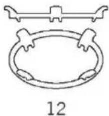
natural_image
Simple line drawing of a decorative ring with a top handle and base plate, labeled '12' below (no text or symbols on the diagram itself)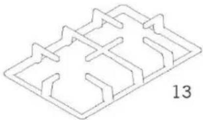
natural_image
Isometric line drawing of a 3D maze-like structure with no text or symbols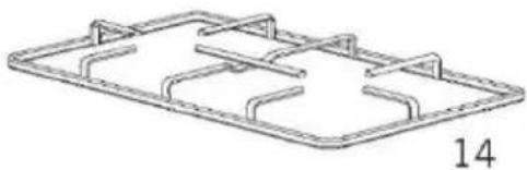
natural_image
Isometric line drawing of a rectangular frame with internal cutouts and no text or symbolsnatural_image
Three technical line drawings showing a mechanical device, a four-circled heating plate, and a final electrical enclosure (no text or symbols present)
natural_image
Simple line drawing of a horizontal beam with two supports at both ends (no text or symbols)natural_image
Simple line drawing of a mechanical component with a cross mark, no text or symbols present
natural_image
Diagram of a gas stove with a downward arrow indicating downward motion (no text or symbols)Figura 7
natural_image
Line drawing of a hand holding a circular object with directional arrows indicating motion (no text or symbols)natural_image
Line drawing of a hand holding a circular object with motion arrows indicating rotation (no text or symbols)natural_image
Line drawing of a hand holding an object with motion arrows indicating rotation (no text or symbols)natural_image
Technical line drawing of a mechanical component with concentric rings and mounting brackets (no text or symbols)natural_image
Silhouette of a cooking pot with steam rising and marked with an 'X' (no text or symbols)natural_image
Silhouette of a cooking pot with a checkmark inside, no text or symbols presentnatural_image
Symbol of a trash bin crossed with no text or numbers, representing environmental protection (no text present)natural_image
U-shaped pipe diagram with a checkmark indicating a specific section (no text or symbols present)Pravilno

natural_image
Diagram of a U-shaped tube with a bulb inserted, marked with an 'X' symbol (no text or labels present)Napačno
natural_image
Illustration of a flexible hose with a checkmark indicating selection (no text or symbols present)Pravilno

Pravilno
natural_image
Line drawing of a mechanical component with cylindrical ports and a central hub (no text or symbols)Slika 2

natural_image
Technical line drawing of a mechanical component with rotating shaft and flange (no text or symbols)Slika 3
natural_image
Simple line drawing of a circular mechanical component with two cylindrical parts and a central rod (no text or symbols)Slika 4

natural_image
Technical line drawing of a mechanical assembly (no text or symbols visible)Slika 5
natural_image
Technical line drawing of a mechanical component with a central shaft and circular base (no text or symbols)
natural_image
Technical line drawing of a mechanical component with a central shaft and circular base (no text or symbols)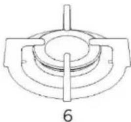
natural_image
Technical line drawing of a mechanical component with concentric rings and a central shaft (no text or symbols)
natural_image
Technical line drawing of a mechanical component with concentric rings and a central shaft (no text or symbols)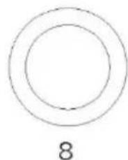
natural_image
Two concentric circles with the number 8 below (no text or symbols within the circles)
natural_image
Simple black circle outline with the number 9 below it (no text or symbols inside)
natural_image
Simple geometric diagram showing a circle partially overlapping a larger circle, labeled with the number 10 below (no text or symbols within the shapes)
natural_image
Simple line drawing of a four-way X-shaped pipe or tube structure (no text or symbols)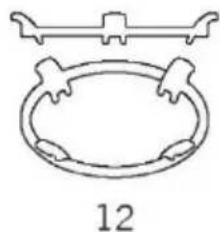
natural_image
Simple line drawing of a circular object with two protruding arms above it, labeled '12' below (no text or symbols on the object itself)
natural_image
Isometric line drawing of a maze-like structure with no text or symbols
natural_image
Technical line drawing of a rectangular frame with internal channels and a label '14' (no text or symbols on the diagram itself)natural_image
Three technical line drawings of electrical heating devices: a tool, a four-circled appliance, and a battery pack (no text or symbols)
natural_image
Simple line drawing of a horizontal beam with two supports at both ends (no text or symbols)natural_image
Simple line drawing of a circular object on a platform with a cross symbol above, no text or labels present.
natural_image
Technical line drawing of a mechanical component with concentric rings and a downward arrow indicator (no text or symbols)Slika 7
natural_image
Line drawing of a hand holding a circular object with directional arrows indicating movement (no text or symbols)natural_image
Hand holding a circular object with motion arrows indicating rotation (no text or symbols)natural_image
Hand holding a finger with motion arrows indicating rotation (no text or symbols)natural_image
Technical line drawing of a mechanical component with concentric rings and mounting brackets (no text or symbols)natural_image
Simple black-and-white icon of a cooking pot with steam rising, no text or symbols presentnatural_image
Silhouette of a cooking pot with a checkmark inside, no text or symbols presentUporabljajte samo lonce in ponve z ravnim dnom.
VZDRŽEVANJE IN ČIŠČENJE
natural_image
Symbol of a trash bin crossed with diagonal lines, no text or numbers presentnatural_image
Technical line drawing of a mechanical component with no visible text or symbolsΕικόνα 2

natural_image
Technical line drawing of a mechanical component with rotating shaft and base (no text or symbols)Εικόνα 3
natural_image
Simple line drawing of a circular mechanical component with two cylindrical parts and a central shaft (no text or symbols)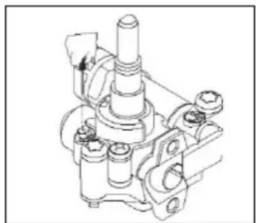
natural_image
Technical line drawing of a mechanical assembly with no visible text or symbolsΕικόνα 4 Εικόνα 5
natural_image
Technical line drawing of a mechanical component with a central shaft and circular base (no text or symbols)
natural_image
Technical line drawing of a mechanical component with a central shaft and concentric rings (no text or symbols)
natural_image
Technical line drawing of a mechanical component with concentric rings and a central shaft (no text or symbols)
natural_image
Technical line drawing of a mechanical component with concentric rings and a central shaft (no text or symbols)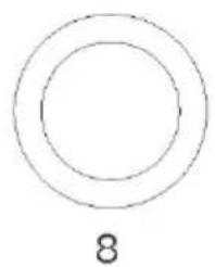
natural_image
Simple diagram of two concentric circles with the number 8 below (no text or symbols within the circles)
natural_image
Simple black circle outline with the number 9 below it (no text or symbols inside)
natural_image
Simple line drawing of a circle connected to an oval shape, labeled with the number 10 below (no text or symbols within the shapes)
natural_image
Simple line drawing of a symmetrical X-shaped structure with no text or symbols
natural_image
Simple line drawing of a circular frame with decorative elements, no text or symbols present
natural_image
Isometric line drawing of a mechanical or architectural component with symmetrical slots and brackets (no text or symbols)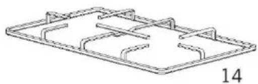
natural_image
Technical line drawing of a rectangular frame with internal supports and a label '14' (no text or symbols on the diagram itself)natural_image
Technical line drawings of electrical heating devices including a power tool, four circular burners, and a rectangular electronic device (no text or symbols)
natural_image
Pure technical line drawing of a horizontal beam with two supports at both ends (no text or symbols)natural_image
Diagram of a mechanical device with a circular component and a cross mark, no readable text or symbols present
natural_image
Technical line drawing of a mechanical component with concentric rings and mounting brackets (no text or symbols)Εικόνα 7
natural_image
Line drawing of a hand holding a small object with directional arrows indicating motion (no text or symbols)natural_image
Line drawing of a hand holding a circular object with an arrow indicating rotation (no text or symbols)natural_image
Line drawing of a hand holding a circular object with directional arrows indicating rotation (no text or symbols)natural_image
Technical line drawing of a mechanical component with concentric rings and mounting brackets (no text or symbols)natural_image
Silhouette of a cooking pot with steam rising and marked with an 'X' (no text or symbols)natural_image
Silhouette of a cooking pot with a checkmark inside, no text or symbols presentnatural_image
Symbol of a trash bin crossed with no text or numbers, representing waste sorting or restriction (no text present)- Dear User,
- Contens
- IMPORTANT WARNINGS
- GB
- Electrical Safety
- Gas Safety
- What To Do When Gas Odour Is Detected
- Intended Use
- Methods for Protecting Ceramic Glass Cooking Surface
- Electrical Connection
- Electrical connection scheme
- Gas Connection
- For LPG connection;
- Transformation from natural gas to LPG and from LPG to natural gas
- Ventilation Of Room
- INTRODUCTION OF THE APPLIANCE
- INSTALLATION OF COOKTOP
- Installation
- Installation Diagram
- If Built-In Oven Is Placed Under Cooktop
- Counter Cut-Off Dimensions
- CONTROL PANEL
- Cooktop Panel Visual Of 90 cm
- Cooktop Panel Visual Of 60 cm
- USAGE OF YOUR COOKTOP
- Wok Burner \*
- Using The Ceramic Hobs
- Turning the ceramic hobs on
- Turning the ceramic hobs off
- Pot Sizes
- MAINTENANCE AND CLEANING
- TROUBLESHOOTING
- Check Points
- HANDLING RULES
- ENVIRONMENTALLY-FRIENDLY DISPOSAL
- PACKAGE INFORMATION
- Gentile cliente,
- IT
- Ako se ugradbena pećnica postavlja ispod ploče za kuhanje
- Dimenzije izreza na radnoj ploči
- UPRAVLJAČKA PLOČA
- Ploča ploče za kuhanje vizualno od 90 cm
- Uporaba keramičkih ploča za kuhanje
- ODRŽAVANJE I ČIŠĆENJE
- RJEŠAVANJE PROBLEMA
- Ventilația camerei
- VZDRŽEVANJE IN ČIŠČENJE
Brand : CANDY
Model : CMG2V2BG
Category : Cooker