
FDQ01 - Battery charger Scosche - Free user manual and instructions
Find the device manual for free FDQ01 Scosche in PDF.


| Product Type | Qi Wireless Charger Mount for Vehicles |
| Brand | Scosche |
| Model | FDQ01 |
| Compatibility | Qi-enabled smartphones: Apple, Samsung, Google, Microsoft, LG, HTC, Motorola |
| Charging Standards | Qi Wireless Charging |
| Power Output | 5W / 10W |
| Input Voltage | Vehicle 12V socket |
| Connector Type | Type-C |
| LED Indicators | Standby: Green; Charging: Blue; Power ON: Blue, Green, Blue blink sequence |
| Mounting Type | Direct Fit Bezel with MAGICPLATE magnetic mount |
| Installation Type | Hardwired into vehicle 12V system (requires vehicle disassembly) |
| Parts Included | Direct Fit Bezel w/ MQUSM, Support Base, Vehicle Specific T-harness, 2 MAGICPLATES, MAGICPLATE Applicator |
| Safety | Magnets harmful if swallowed; keep away from children; avoid airbag wiring |
| Warranty | Contact manufacturer for replacement parts |
| Vehicle Fitment | F-150 trucks with center cup/storage console (not compatible with Raptor models) |
| Material | High powered neodymium magnets, plastic bezel |
| Special Features | Magnetic mount with template guide; LED charging status |
Frequently Asked Questions - FDQ01 Scosche
User questions about FDQ01 Scosche
0 question about this device. Answer the ones you know or ask your own.
Ask a new question about this device
Download the instructions for your Battery charger in PDF format for free! Find your manual FDQ01 - Scosche and take your electronic device back in hand. On this page are published all the documents necessary for the use of your device. FDQ01 by Scosche.
USER MANUAL FDQ01 Scosche
(For F-150 trucks with center cup/storage console.
Not compatible with Raptor models)
PARTS INCLUDED
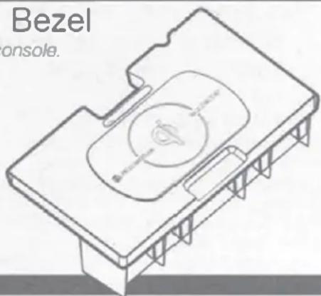
- (1) Direct Fit Bezel w/ MQUSM
- (1) Support Base
- (1) Vehicle Specific T-harness
- (2) MAGICPLATES
- (1) MAGICPLATE™ Applicator
READ INSTRUCTIONS COMPLETELY BEFORE INSTALLING THIS MOUNT KIT.
WARNING: Do not use the magnetic mount with any hard-drive based devices such as: iPod classic, iPod Video and Zune MP3 players. Use caution whenever removing or
handling plastic parts of any vehicle. Unnecessary force or pressure can cause pieces to crack or break. Please use a plastic card to remove the metal plates. Remove adhesive residue with a non-abrasive cleaner.
CAUTION: This magnetic device is not a toy. The small magnets are harmful if swallowed. Keep away from children.
PRELIMINARY INTRODUCTION
Wirelessly charge your Qi-enabled smartphone without the need to plug your device into a car charger or USB cable. Quickly charge your device at 5W or 10W charging. The high powered neodymium magnets are 100% safe and will not damage your device. The FDQ01 works with Qi-enabled smartphones from these manufacturers: Apple, Samsung, Google, Microsoft, LG, HTC, Motorola. Also works with Qi-enabled cases, receivers, and battery covers.
CAUTION: Disconnect your vehicles negative battery terminal before the installation to help prevent electrical damage. We recommend the use of a volt/ ohm meter over a test light to check wiring. A test or grounded wire probe can cause damage to the vehicle's computer and/or diagnostic system. Avoid all factory airbag wiring - airbags can accidentally deploy causing serious injury or death.
NOTE: See your vehicle's instructions for any special tools your installation might require.
IMPORTANT! DO NOT RETURN PRODUCT TO THE RETAILER. If you need assistance or
replacement parts contact us at: 1-800-363-4490 X1 | www.scosche.com/contact. Our office hours are: Mon-Fri: 8AM-5:30PM (PST) and Sat: 8am-2PM (PST)
LIABILITY DISCLAIMER
This instruction booklet is based on carefully documented data and research of automobile disassembly, wire harness and information pertaining to the installation of this kit. Scosche Industries, Inc. cannot be held responsible for discrepancies/inconsistencies that may occur due to the automobile manufacturing changes or options, or damages that may occur in the automobile during the installation of components while using this booklet.
MAGICPLATE™ MOUNTING OPTION 1
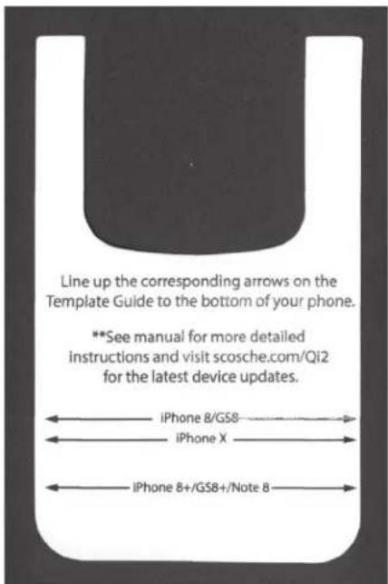
NOTE: For mounting directly to device, use the large single plate with template guide as shown in the instructions below.
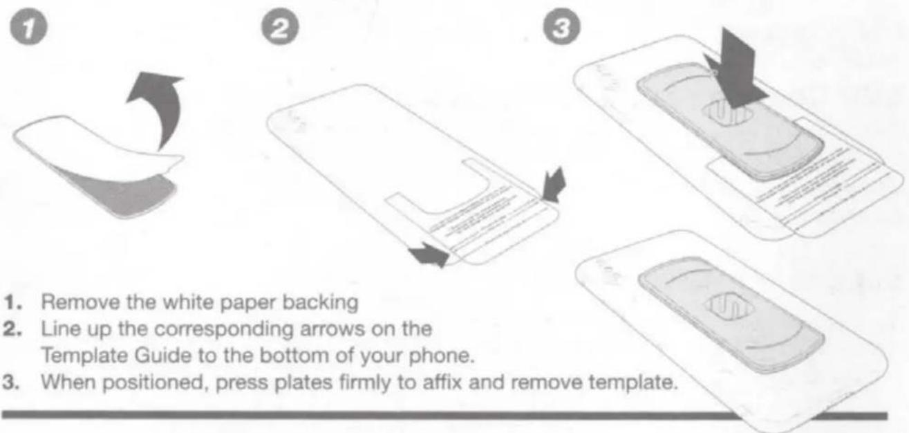
- Remove the white paper backing
- Line up the corresponding arrows on the Template Guide to the bottom of your phone.
- When positioned, press plates firmly to affix and remove template.
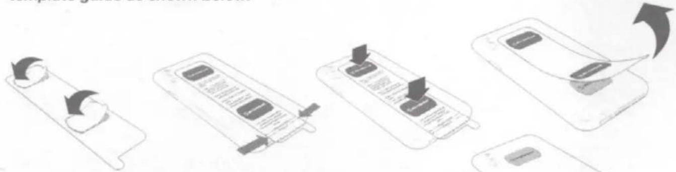
MAGICPLATE™ MOUNTING OPTION 2
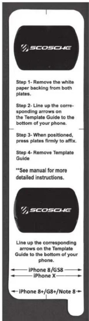
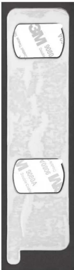
NOTE: For mounting directly to CASE, use the (2) small plates with the integrated template guide as shown below.
flowchart
graph TD
    A["Device 1: Battery Input"] --> B["Device 2: Display"]
    B --> C["Device 3: Screen Display"]
    C --> D["Device 4: Screen Display with Button"]
    D --> E["Device 5: Display with Arrow"]
- Remove the white paper backing from both plates
- Line up the corresponding arrows on the Template Guide to the bottom of your phone.
- When positioned, press plates firmly to affix.
- Lastly, remove the template guide.
REMOVING THE METAL PLATE
Use a thin plastic card to carefully lift the plate's adhesive surface from the mounting surface. Slowly lift up and remove the plate. Do not use any heat or liquids to remove the plate, due to risk of damaging your phone. Contact Scosche Customer Service for any additional assistance at 800.363.4490 Ext. 1 or customerservice@scosche.com
Modification Required: Please read complete instructions before proceeding. Location modification required for this installation, proceed with caution. If you are unsure or feel that the installation is to difficult, we recommend you seek professional installation. Note that additional installation fees may apply and vary by location. Scosche is not responsible or liable for any additional fees or modification done by the installer.
LED Charging Status: The LED indicator on the side of the mount illuminates the charging status of the device. When powered ON, the indicator blinks in the following order BLUE, GREEN, BLUE.
Standby = Green
Charging = Blue
natural_image
Pure technical line drawing of intersecting lines without any text, numbers, or symbolsVehicle Disassembly
-
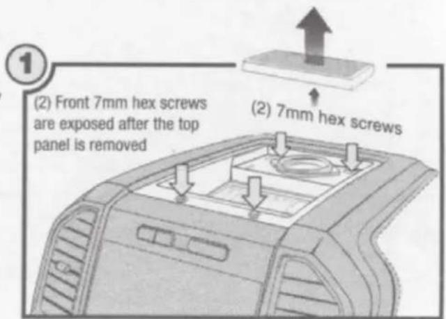
Using a panel removal tool, carefully pry and remove the speaker grille located on the top of the dash. Second, unscrew the (2) 7mm hex screws exposed. Third, using a panel removal tool, unclip the top panel (highlighted) and unplug/unclip any wiring then set aside for re-installation. Fourth, remove the (2) 7mm screws exposed (securing the stereo face panel).
-
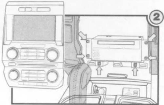
Using a panel removal tool carefully pry and pull the radio face panel away and disconnect it from the center dash. Second, remove the lower plastic trim panel being held by two screws (trim not shown see screw locations on illustration #2). Third, unscrew the (4) 7mm screws securing the CD player and unplug/unclip any wires, then carefully set aside for re-installation. Fourth open the lower acc. tray compartment door.
-
If not already done, place the parking brake ON and set the gear shift to neutral (illustration 3, #1). Open the center console's arm rest and carefully pry (illustration 3, #2) the cup holder/shifter panel from the center console. Once the panel is loose, carefully pull the panel back and upwards away from location, then set aside for re-installation.
natural_image
Interior view of a car dashboard and infotainment system (no visible text or symbols)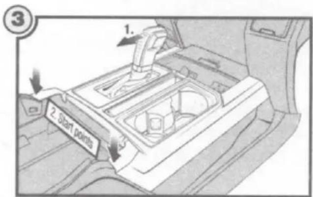
Vehicle Disassembly (con't)
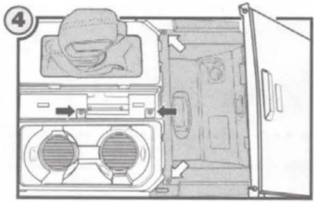
- Remove (2) t-20 screws securing the lower tray door (white arrows), then carefully lift, remove and disconnect any attachements. After removing the tray door, unscrew the (2) t-20 screws securing the cup holder panel (black arrows), then lift and turn slightly to gain access to the cavity. Note: It is NOT necessary to completely detach from the leather, only shift aside.
\*Testing Connection
Before proceeding to the installation please test the modules functionality by connecting the provided vehicle specific t-harness (diagram on right). Once the module is connected, place the Qi-enabled device on the module and refer to the LED Status chart below for specifics. For technical assistance with the installation please call or visit us on the web at: 1-800-363-4490 x1 | www.scosche.com/contact
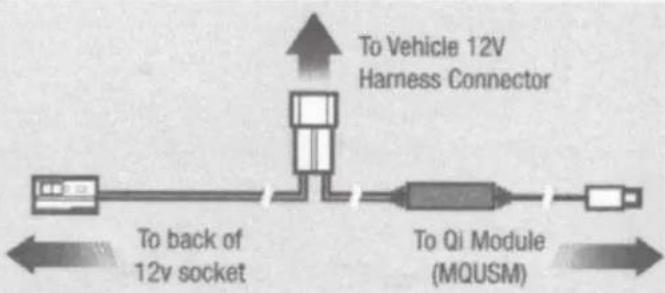
flowchart
graph LR
    A["Device 1"] --> B["To back of 12v socket"]
    B --> C["To Vehicle 12V Harness Connector"]
    C --> D["To Qi Module (MQUSM)"]
    D --> E["Output"]
Installation/Assembly
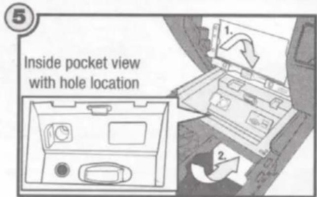
- Carefully reach through the CD player cavity (illustration 5,#1) and disconnect the 12v socket harness. Route the vehicle specific t-harness from the cup holder cavity to the 12v socket and make the necessary connections (illustration 5, #2). *Test Connection before modifying. After testing, disconnect the Type-c connector from the module and create a hole big enough to pass the type-c connection through the acc. pocket. See recommended hole location in illustration. Next, carefully reach under with the type-c cable and pass the connector through the hole created. Lastly, tuck and hide away any harness excess within the cup holder cavity and proceed to the next step.
-
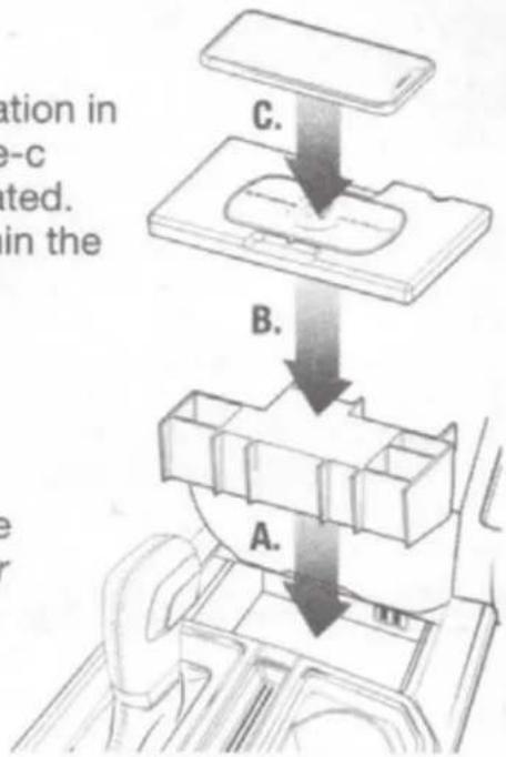
Qi Bezel Assembly: Place the lower support structure into the center console pocket (A). Carefully align the top Qi bezel to the support structure in the pocket (connected to type-c) (B). Lastly, place the Qi-enabled device onto the module surface (C). (See LED Charging Status on page 3 for details).
-
Reassemble everything in reverse order of disassembly to complete the installation
- PARTS INCLUDED
- READ INSTRUCTIONS COMPLETELY BEFORE INSTALLING THIS MOUNT KIT.
- PRELIMINARY INTRODUCTION
- IMPORTANT! DO NOT RETURN PRODUCT TO THE RETAILER. If you need assistance or
- LIABILITY DISCLAIMER
- MAGICPLATE™ MOUNTING OPTION 1
- MAGICPLATE™ MOUNTING OPTION 2
- REMOVING THE METAL PLATE
- Vehicle Disassembly
- Vehicle Disassembly (con't)
- \*Testing Connection
- Installation/Assembly
Brand : Scosche
Model : FDQ01
Category : Battery charger