
GMQ02 - Battery charger Scosche - Free user manual and instructions
Find the device manual for free GMQ02 Scosche in PDF.


| Product Type | Battery Charger & Maintainer |
| Brand | Scosche |
| Model | GMQ02 |
| Compatible Battery Types | Lead-Acid (AGM, Gel, Flooded), Li-Ion |
| Input Voltage | 100-240 V AC, 50-60 Hz |
| Output Voltage | 12 V DC |
| Charging Current | 2 A (Maintain), 6 A (Fast Charge) |
| Dimensions (L x W x H) | 6.0 x 3.0 x 1.5 inches |
| Weight | 1.2 lbs (0.54 kg) |
| Protection Features | Reverse Polarity, Overcharge, Short Circuit, Spark-Proof |
| Charging Modes | Automatic, Manual, Maintenance/Trickle |
| LED Indicators | Power, Charging, Fully Charged, Error |
| Cable Length | 3 ft (0.9 m) with clamps |
| Operating Temperature | -20°C to 50°C (-4°F to 122°F) |
| Storage Temperature | -30°C to 70°C (-22°F to 158°F) |
| Certifications | CE, RoHS, FCC |
| Maintenance | Keep dry, clean contacts, store in a cool place |
| Repairability / Spare Parts | Replaceable fuse (5 A, 250 V) |
Frequently Asked Questions - GMQ02 Scosche
User questions about GMQ02 Scosche
0 question about this device. Answer the ones you know or ask your own.
Ask a new question about this device
Download the instructions for your Battery charger in PDF format for free! Find your manual GMQ02 - Scosche and take your electronic device back in hand. On this page are published all the documents necessary for the use of your device. GMQ02 by Scosche.
USER MANUAL GMQ02 Scosche
2014-15 SELECT GM TRUCKS
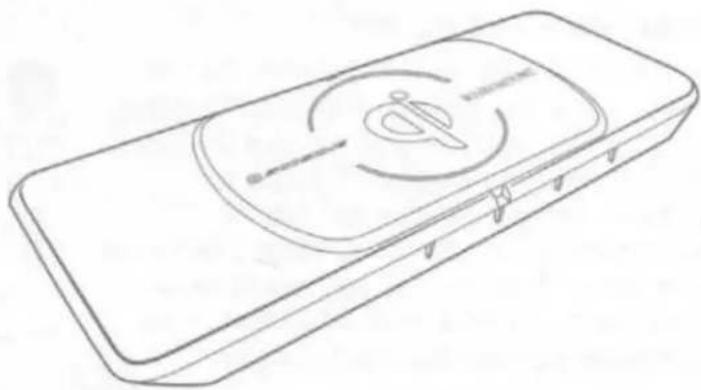
Qi Center Console Direct Fit Bezel
PARTS INCLUDED
- (1) MAGICMOUNT™ Qi Module
- (2) MAGICPLATE™
- (2) MAGICPLATE™ Applicator
- (6) Two-sided adhesive
- (1) Vehicle Specific T-harness
natural_image
Line drawing of a rectangular electronic device with a circular button and pointer symbol on the lid (no text or labels)READ INSTRUCTIONS COMPLETELY BEFORE INSTALLING THIS MOUNT KIT.
WARNING: Do not use the magnetic mount with any hard-drive based devices such as: iPod classic, iPod Video and Zune MP3 players. Use caution whenever removing or handling plastic parts of any vehicle. Unnecessary force or pressure can cause pieces to crack or break. Please use a plastic card to remove the metal plates. Remove adhesive residue with a non-abrasive cleaner.
AIRBAG WARNING:
Do not place this pad or any other object on or near the airbag. In the event of deployment, objects placed on or near airbag could cause serious injury.
CAUTION: This magnetic device is not a toy. The small magnets are harmful if swallowed. Keep away from children.
PRELIMINARY INTRODUCTION
Wirelessly charge your Qi-enabled smartphone without the need to plug your device into a car charger or USB cable. Quickly charge your device at 5W or 10W charging. The high powered neodymium magnets are 100% safe and will not damage your device. The GMQ02 works with Qi-enabled smartphones from these manufacturers: Apple, Samsung, Google, Microsoft, LG, HTC, Motorola. Also works with Qi-enabled cases, receivers, and battery covers.

IMPORTANT! DO NOT RETURN PRODUCT TO THE RETAILER
IF YOU NEED ASSISTANCE OR REPLACEMENT PARTS
CALL US TOLL FREE: 1-800-363-4490 X1
HOURS MON-FRI 8AM-5:30PM (PST) SATURDAY 8AM-2PM (PST)
MAGICPLATE™ MOUNTING OPTION 1
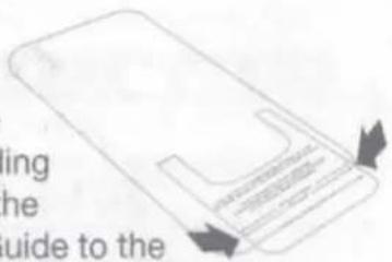
NOTE: For mounting directly to device, use the large single plate with template guide as shown in the instructions below.

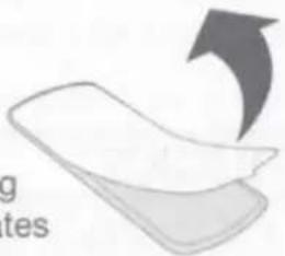
Remove the white paper backing from both plates
natural_image
Illustration of a folded paper or sheet with an arrow indicating rotation (no text or symbols)
Line up the corresponding arrows on the Template Guide to the to the bottom of your phone.
REMOVING THE PLATE
Use a thin plastic card to carefully lift the plate's adhesive surface from the mounting surface. Slowly lift up and remove the plate. Do not use any heat or liquids to remove the plate, due to risk of damaging your phone. Contact Scosche Customer Service for any additional assistance at 800.363.4490 Ext. 1 or customerservice@scosche.com

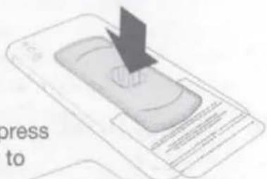
When positioned, press plates firmly to affix and remove template.
MAGICPLATE™ MOUNTING OPTION 2
NOTE: For mounting directly to CASE, use the (2) small plates with the integrated template guide as shown below.

Remove the white paper backing from both plates
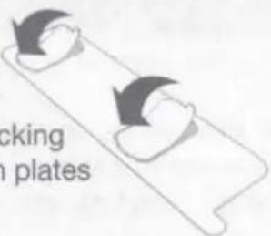

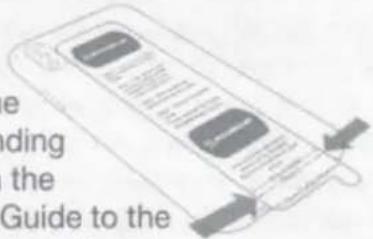
Line up the corresponding arrows on the Template Guide to the to the bottom of your phone.

When positioned, press plates firmly to affix.
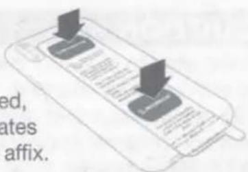

Lastly, remove the template guide.
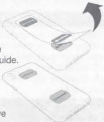
natural_image
Two smartphone panels with a slide and a slide cover, shown from different angles (no text or symbols visible)REMOVING THE METAL PLATE
Use a thin plastic card to carefully lift the plate's adhesive surface from the mounting surface. Slowly lift up and remove the plate. Do not use any heat or liquids to remove the plate, due to risk of damaging your phone. Contact Scosche Customer Service for any additional assistance at 800.363.4490 Ext. 1 or customerservice@scosche.com
MAGICPLATE™ MOUNTING OPTION 3 (Continued)
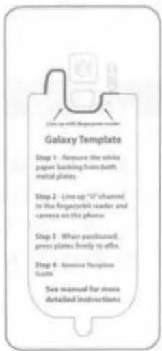
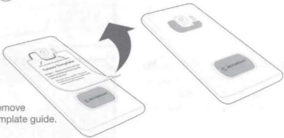
NOTE: For mounting directly* to Galaxy S9/S9+, use the (2) small plates with the integrated template guide for Galaxy as shown. *For mounting directly to device only. Do not mount to case.

Remove the white paper backing from both plates.
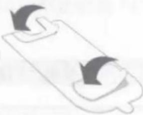
natural_image
Simple line drawing of a clipboard with two curved arrows indicating rotation (no text or symbols)
Line up "U" channel to the fingerprint reader and camera on the phone.

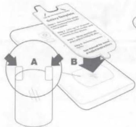
Remove the backing from the protective film as shown on the removal tabs (A), and place between the device and the lower plate (B). The protective film must be used when applying MAGICPLATETM directly to the back of device.
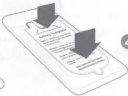

When positioned, press plates firmly to affix.

Remove template guide.
flowchart
graph TD
    A["Gallery Template"] -->|Remove Template Guide.| B["File Transfer"]
    B --> C["Downloading Software"]
    C --> D["Downloaded Software"]
REMOVING THE METAL PLATE
Use a thin plastic card to carefully lift the plate's adhesive surface from the mounting surface. Slowly lift up and remove the plate.
Do not use any heat or liquids to remove the plate, due to risk of damaging your phone. Contact Scosche Customer Service for any additional assistance at 800.363.4490 Ext. 1 or customerservice@scosche.com
Modification Required: Please read complete instructions before proceeding. Location modification required for this installation, proceed with caution. If you are unsure or feel that the installation is to difficult, we recommend you seek professional installation. Note that additional installation fees may apply and vary by location. Scosche is not responsible or liable for any additional fees or modification done by the installer.
VEHICLE DISASSEMBLY
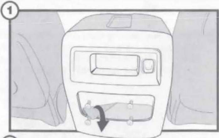
- Remove mat from the center console's back panel, then remove (4) screws exposed.
- Carefully remove the center console's back panel using a panel removal tool.
- Disconnect the 12V power connection from the panel and proceed to the next step of the disassembly.
natural_image
Diagram of a car air conditioner unit with a directional arrow indicating airflow or movement (no text or symbols)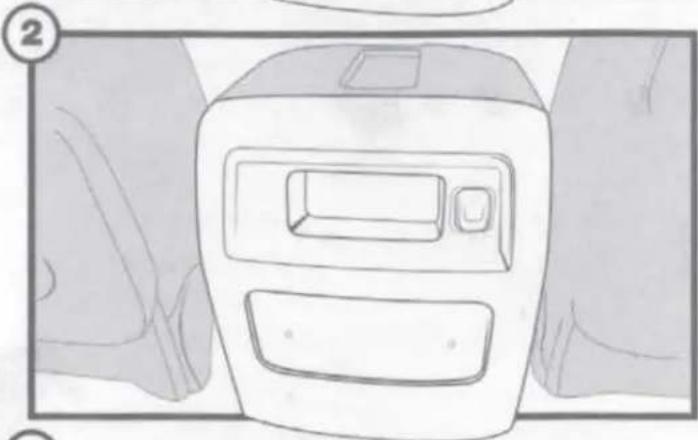
natural_image
Line drawing of a car air conditioner unit with two vent slots and a side panel, shown in perspective view (no text or symbols)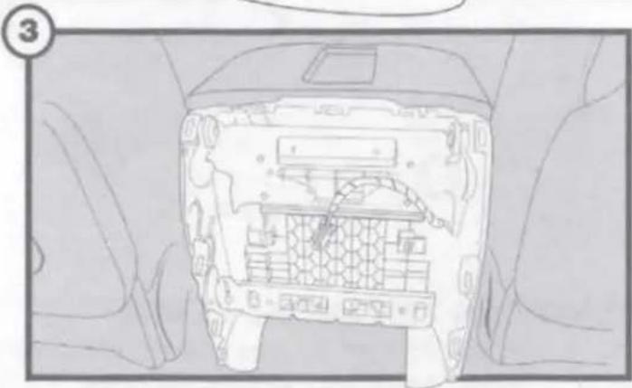
natural_image
Top-down view of a car interior showing internal compartments and structural elements (no text or symbols)VEHICLE DISASSEMBLY
Cont'd
- Remove the rubber mat located on the center console's arm rest.
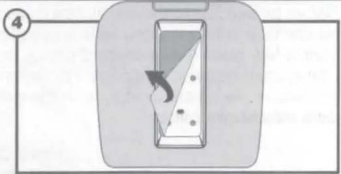
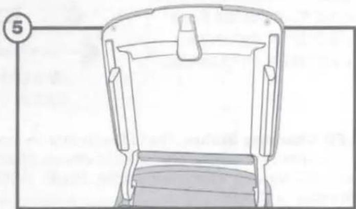
- Use a panel removal tool to remove the plastic panel under the armrest lid.
natural_image
Line drawing of a mechanical device with no visible text or symbolsASSEMBLY PREPARATION
Modification Required Proceed with CAUTION!
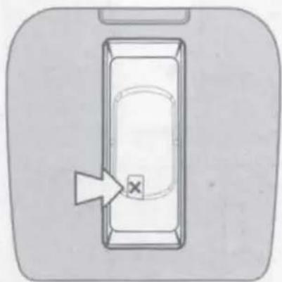
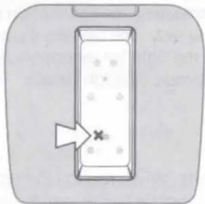
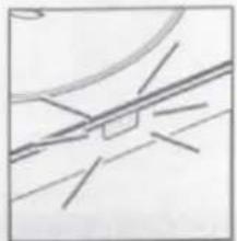
Carefully make a hole large enough to pass the Type-C connection through the recommended area shown in the illustrations below.
NOTE: For a more accurate result, place the Qi bezel without the module (MQUSM) into the vehicle's armrest. Once bezel is in place use a contrasting chalk or marker and place a mark for the hole location, see illustrations below for details.
natural_image
Simple line drawing of a rectangular object with an arrow pointing to it, no text or symbols present.- Place the Qi bezel into armrest and place a mark where the hole will be located, then remove the bezel.
natural_image
Simple line drawing of a tray with a star symbol inside, no text or labels present- Carefully make a hole through the armrest tray large enough to pass the Type-C connector. Note: Tray mat is not retained for this installation.
Testing Connection
Before proceeding to the installation please test the modules functionality by connecting the provided vehicle specific t-harness. Once the module is connected, place the Qi-enabled device on the module and refer to the LED Status chart below for specifics. For technical assistance with the installation please call or visit us on the web at: 1-800-363-4490 x1 | www.scosche.com/contact
Note: The module can also be tested by connecting it to a USB to type-c connection power source (not included).
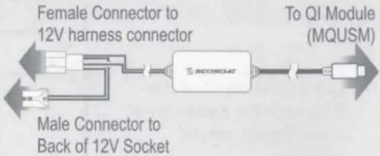
flowchart
graph LR
    A["Female Connector to 12V harness connector"] --> B["SCOSO4"]
    C["Male Connector to Back of 12V Socket"] --> B
    B --> D["To QI Module (MQUSM)"]
LED Charging Status: The LED indicator on the side of the mount illuminates the charging status of the device. When powered ON, the indicator blinks in the following order: BLUE, GREEN, BLUE.
Standby = Green
Charging = Blue
natural_image
Pure geometric lines forming a cross-like pattern without any text, numbers, or symbolsASSEMBLY
Routing Harness
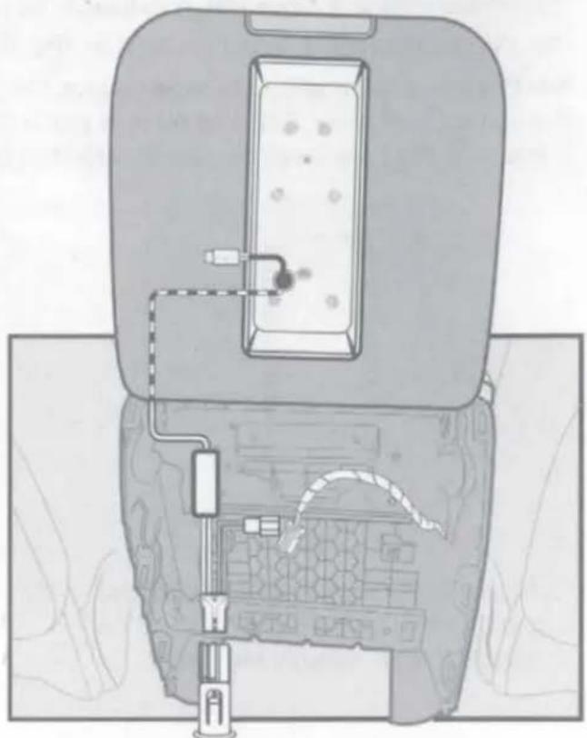
- Make all of the necessary wiring connections with the provided vehicle t-harness at the center console's back panel. Use the diagram illustrated above (Testing Connection) for connection details. You may also use the illustration at the right for recommended harness location details.
Note: When routing the type-c connector to the center console's lid, we recommend routing through either the left or right lid hinge opening. See the illustration at right for example.
natural_image
Top-down diagram of a car interior showing dashboard, vent, and control panel (no text or symbols)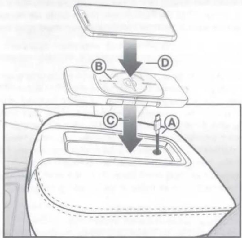
- Once all connections have been made to the t-harness provided assemble the Qi kit into the designated location in the order listed below.
A. Route/Pass the type-c connector through the armrest center console's hole created during the ASSEMBLY PREPARATION step on page 5.
B. Place the Qi module (MQUSM) into the provided GMQ02 (7964) bezel and connect the type-c connection
C. Place the bezel assembly into the armrest tray area.
Note:
- OEM mat is not retained for this kit.
- Use the provided two-sided adhesive to secure the bezel in place.
D. Place the Qi enabled device onto the module to confirm functionality.
E. Once the functionality of the module is confirmed reassemble everything in reverse order to complete the installation.
TECH SUPPORT
If you have any questions or need technical assistance with the installation, or the most current application please call or visit us on the web at:
(800) 363-4490 x1 | www.scosche.com/contact
FCC STATEMENT
This equipment has been tested and found to comply with the limits for a WPC device, pursuant to Part 18 of the FCC Rules. These limits are designed to provide reasonable protection against harmful interference in a residential installation.
CAUTION: Changes or modifications not expressly approved by the party responsible for compliance could void the user's authority to operate the product.
NOTE: This equipment has been tested and found to comply with the limits for a wireless power charger, pursuant to Part 18 of the FCC Rules. These limits are designed to provide reasonable protection against harmful interference in a residential installation. This equipment generated, uses and can radiate radio frequency energy and, if not installed and used in accordance with the instructions, may cause harmful interference to radio communications. However there is no guarantee that interference will occur in a particular installation. If this equipment does cause harmful interference to radio or television reception, which can be determined by turning the equipment off and on, the user in encouraged to try to correct the interference by one or more of the following measures:
- Reorient or relocate the receiving antenna.
- Increase the separation between the equipment and receiver.
- Connect the equipment into an outlet on a circuit different from that to which the receiver is connected.
- Consult the dealer or an experienced radio/TV technician for help.
IC STATEMENT
This device complies with industry Canada License-exempt RSS standard(s). Operation is subject to the following two conditions: (1) this device may not cause interference, and (2) this device must accept any interference, including interference that may cause undesired operation of the device. This equipment complies with IC RSS-102 radiation exposure limits set forth for an uncontrolled environment. This transmitter must not be co-located or operated in conjunction with any other antenna or transmitter.
For complete warranty details or questions visit us online at www.scosche.com or contact us at:
www.scosche.com/contact customerservice@scosche.com 1(800) 363-4490 ext.1
- 2014-15 SELECT GM TRUCKS
- PARTS INCLUDED
- READ INSTRUCTIONS COMPLETELY BEFORE INSTALLING THIS MOUNT KIT.
- AIRBAG WARNING:
- PRELIMINARY INTRODUCTION
- IMPORTANT! DO NOT RETURN PRODUCT TO THE RETAILER
- MAGICPLATE™ MOUNTING OPTION 1
- REMOVING THE PLATE
- MAGICPLATE™ MOUNTING OPTION 2
- REMOVING THE METAL PLATE
- MAGICPLATE™ MOUNTING OPTION 3 (Continued)
- VEHICLE DISASSEMBLY
- ASSEMBLY PREPARATION
- Modification Required Proceed with CAUTION!
- Testing Connection
- ASSEMBLY
- Note:
- TECH SUPPORT
- FCC STATEMENT
- IC STATEMENT
Brand : Scosche
Model : GMQ02
Category : Battery charger