
P604IM2B2NE-20 - Cooker BERTAZZONI - Free user manual and instructions
Find the device manual for free P604IM2B2NE-20 BERTAZZONI in PDF.


| Product Type | Built-in Cooker |
| Brand | Bertazzoni |
| Model | P604IM2B2NE-20 |
| Width | 60 cm |
| Depth | 60 cm |
| Height | 85-90 cm (adjustable) |
| Weight | Approximately 55 kg |
| Power Supply | Gas (G20/G30) and electric 230 V / 50 Hz |
| Hob | 4 gas burners with integrated ignition |
| Burner Power | From 1.0 kW to 3.5 kW depending on burner |
| Oven | Multi-function electric |
| Oven Capacity | Approximately 70 liters |
| Oven Functions | Convection, grill, bottom heat, defrost, light |
| Cleaning Type | Pyrolytic |
| Energy Class | A (oven) |
| Safety | Gas cut-off device (thermocouple) on burners, child safety, oven door lock |
| Spare Parts | Grills, trays, burners, thermostats available via authorized service |
| Repairability | Repairability index not communicated |
| Included Accessories | Grill, drip tray, temperature probe |
| Warranty | 2 years (according to legislation) |
Frequently Asked Questions - P604IM2B2NE-20 BERTAZZONI
User questions about P604IM2B2NE-20 BERTAZZONI
0 question about this device. Answer the ones you know or ask your own.
Ask a new question about this device
Download the instructions for your Cooker in PDF format for free! Find your manual P604IM2B2NE-20 - BERTAZZONI and take your electronic device back in hand. On this page are published all the documents necessary for the use of your device. P604IM2B2NE-20 by BERTAZZONI.
USER MANUAL P604IM2B2NE-20 BERTAZZONI
USING THE APPLIANCE 4
PRECAUTIONS TO PREVENT DAMAGE TO THE APPLIANCE 5
PRECAUTIONS IN CASE OF APPLIANCE FAILURE....6
OTHER PROTECTIONS 6
DESCRIPTION OF THE APPLIANCE....7
TECHNICAL CHARACTERISTIC....7
CONTROL PANEL 8
USE OF THE APPLIANCE......8
SENSITIVE TOUCH....8
DISPLAY....8
VENTILATION....8
STARTING-UP AND APPLIANCE MANAGEMENT 9
BEFORE THE FIRST USE....9
INDUCTION PRINCIPLE 9
POWER SELECTION ZONE "SLIDER" AND TIMER SETTING ZONE 9
STARTING-UP 9
PAN DETECTION 10
RESIDUAL HEAT INDICATION 10
POWER BOOSTER AND DOUBLE POWER BOOSTER FUNCTION 10
TIMER 11
AUTOMATIC COOKING 12
STOP&GO FUNCTION....12
RECALL FUNCTION 12
THE PREVIOUS SETTINGS ARE AGAIN ACTIVE....12
BRIDGE FUNCTION 13
COOKING ADVICES....16
PAN QUALITY 16
PAN DIMENSION....16
EXAMPLES OF COOKING POWER SETTING....17
MAINTENANCE AND CLEANING....17
WHAT TO DO IN CASE OF A PROBLEM....17
ENVIRONMENT PRESERVATION 19
INSTALLATION INSTRUCTIONS....20
ELECTRICAL CONNECTION 22
Precautions before usage
- Unpack all the materials.
- The installation and connecting of the appliance have to be done by approved specialists. The manufacturer can not be responsible for damage caused by building-in or connecting errors.
- To be used, the appliance must be well-equipped and installed in a kitchen unit and an adapted and approved work surface.
- This domestic appliance is exclusively for the cooking of food, to the exclusion of any other domestic, commercial or industrial use.
- Remove all labels and self-adhesives from the ceramic glass.
- Do not change or alter the appliance.
- The cooking plate can not be used as freestanding or as working surface.
- The appliance must be grounded and connected conforming to local standards.
- Do not use any extension cable to connect it.
- The appliance can not be used above a dishwasher or a tumble-dryer: steam may damage the electronic appliances.
- The appliance is not intended to be operated by means of external timer or separate remote control system.
Using the appliance
- Switch the heating zones off after using.
- Keep an eye on the cooking using grease or oils: that may quickly ignite.
- Be careful not to burn yourself while or after using the appliance.
- Make sure no cable of any fixed or moving appliance contacts with the glass or the hot saucepan.
- Magnetically objects (credit cards, floppy disks, calculators) should not be placed near to the engaged appliance.
- Do not place any metallic object except heating containers. In case of untimely engaging or residual heat, this one may heat, melt or even burn.
- Never cover the appliance with a cloth or a protection sheet. This is supposed to become very hot and catch fire.
- This appliance is not intended for use by persons (including children) with reduced physical, sensory or mental capabilities, or lack of experience and knowledge, unless they have been given supervision or instruction concerning use of the appliance by a person responsible for their safety.
- Children should be supervised to ensure that they do not play with the appliance.
- Cleaning and user maintenance shall not be made by children.
- Metallic objects such as knives, forks, spoons and lids should not be placed on the hob surface since they can get hot.
- WARNING: The appliance and its accessible parts become hot during use. Care should be taken to avoid touching heating elements. Children shall be kept away unless continuously supervised.
Precautions to prevent damage to the appliance
- Raw pan bottoms or damaged saucepans (not enamelled cast iron pots,) may damage the ceramic glass.
- Sand or other abrasive materials may damage ceramic glass.
- Avoid dropping objects, even little ones, on the vitroceramic.
- Do not hit the edges of the glass with saucepans.
- Make sure that the ventilation of the appliance works according to the manufacturer's instructions.
- Do not put or leave empty saucepans on the vitroceramic hobs.
- Sugar, synthetic materials or aluminium sheets must not contact with the heating zones. These may cause breaks or other alterations of the vitroceramic glass by cooling: switch on the appliance and take them immediately out of the hot heating zone (be careful: do not burn yourself).
- WARNING: Unattended cooking on a hob with fat or oil can be dangerous and may result in fire.
- CAUTION: The cooking process has to be supervised. A short term cooking process has to be supervised continuously.
- WARNING: Danger of fire: do not store items on the cooking surface.
- Never place any hot container over the control panel.
- If a drawer is situated under the embedded appliance, make sure the space between the content of the drawer and the inferior part of the appliance is large enough (3 cm). This is essential to guaranty a correct ventilation.
- Never put any inflammable object (ex. sprays) into the drawer situated under the vitroceramic hob. The eventual cutlery drawers must be resistant to heat.
- Do not use harsh abrasive cleaners or sharp metal scrapers to clean the glass hob since they can scratch the surface, which may result in shattering of the glass.
Precautions in case of appliance failure
- If a defect is noticed, switch off the appliance and turn off the electrical supplying.
- If the ceramic glass is cracked or fissured, you must unplug the appliance and contact the after sales service.
- Repairing has to be done by specialists. Do not open the appliance by yourself.
- WARNING: If the surface is cracked, switch off the appliance to avoid the possibility of electric shock.
Other protections
- Note sure that the container pan is always centred on the cooking zone. The bottom of the pan must have to cover as much as possible the cooking zone.
- For the users of pacemaker, the magnetic field could influence its operating. We recommend getting information to the retailer or of the doctor.
- Do not to use aluminium or synthetic material containers: they could melt on still hot cooking zones.
- NEVER try to extinguish a fire with water, but switch off the appliance and then cover flame e.g. with a lid or a fire blanket.

THE USE OF EITHER POOR QUALITY POT OR ANY INDUCTION ADAPTOR PLATE FOR NON-MAGNETIC COOKWARE RESULTS IN A WARRANTY BREACH. IN THIS CASE, THE MANUFACTURER CANNOT BE HELD RESPONSIBLE FOR ANY DAMAGE CAUSED TO THE HOB AND/OR ITS ENVIRONMENT.

Technical characteristic
| Type | P604IM2B2NE-20 |
| Total power | 7400 W |
| Energy consumption for the hob EC_hob^** | 170.5 Wh/kg |
| Front left heating zone | 210x200 mm |
| Minimum detection | ∅ 90 mm |
| Nominal power* | 2100 W |
| Power Booster* | 2500 W |
| Double Power Booster* | 3000 W |
| Standardised cookware category** | B |
| Energy consumption EC_cw^** | 161.3 Wh/kg |
| Rear left heating zone | 210x200 mm |
| Minimum detection | ∅ 90 mm |
| Nominal power* | 1600 W |
| Power Booster* | 1850 W |
| Double Power Booster* | - |
| Standardised cookware category** | B |
| Energy consumption EC_cw^** | 161.3 Wh/kg |
| Rear right heating zone | 210x200 mm |
| Minimum detection | ∅ 90 mm |
| Nominal power* | 2100 W |
| Power Booster* | 2500 W |
| Double Power Booster* | 3000 W |
| Standardised cookware category** | C |
| Energy consumption EC_cw^** | 177.6 Wh/kg |
| Front right heating zone | 210x200 mm |
| Minimum detection | ∅ 90 mm |
| Nominal power* | 1600 W |
| Power Booster* | 1850 W |
| Double Power Booster* | - |
| Standardised cookware category** | A |
| Energy consumption EC_cw^** | 181.9 Wh/kg |
* The given power may change according to the dimensions and material of the pan. ** calculated according to the method of measuring performance (EN 60350-2).
Control panel
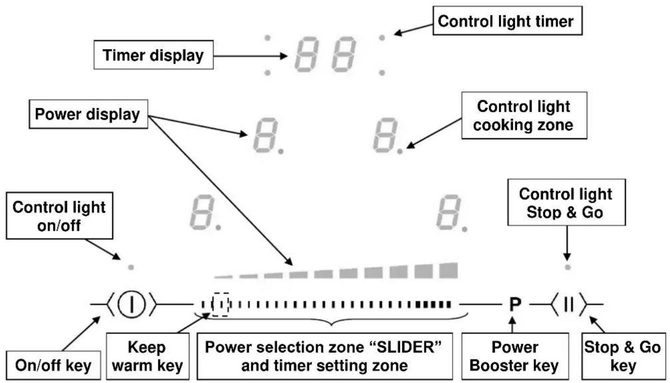
flowchart
graph TD
    A["Timer display"] --> B["8."]
    C["Power display"] --> D["8."]
    E["Control light on/off"] --> F["8."]
    G["On/off key"] --> H["1"]
    I["Keep warm key"] --> J["2"]
    K["Power selection zone "SLIDER" and timer setting zone"] --> L["3"]
    M["Power Booster key"] --> N["P"]
    O["Stop & Go key"] --> P["II"]
    Q["Control light cooking zone"] --> R["8."]
    S["Control light Stop & Go"] --> T["8."]
    U["Control light timer"] --> V["8."]
    W["Control light on/off"] --> X["8."]
    Y["Control light Stop & Go"] --> Z["8."]
    style A fill:#f9f,stroke:#333
    style C fill:#f9f,stroke:#333
    style E fill:#f9f,stroke:#333
    style G fill:#f9f,stroke:#333
    style O fill:#f9f,stroke:#333
    style Q fill:#f9f,stroke:#333
    style U fill:#f9f,stroke:#333
    style W fill:#f9f,stroke:#333
    style X fill:#f9f,stroke:#333
    style Y fill:#f9f,stroke:#333
    style Z fill:#f9f,stroke:#333
USE OF THE APPLIANCE
Sensitive touch
Your ceramic hob is equipped with electronic controls with sensitive touch keys. When your finger presses the key, the corresponding command is activated. This activation is validated by a control light, a letter or a number in the display and/or a “beep” sound.
In the case of a general use press only one key at the same time.
Display
Display Designation Description
- Zero The heating zone is activated.
1...9 Power level Selection of the cooking level.
U No pan detection No pan or inadequate pan.
A Heat accelerator Automatic cooking.
E Error message Electronic failure.
H Residual heat The heating zone is hot.
P Power Booster The Power Booster is activated.
L Locking Control panel locking.
U Keep warm Maintain automatically of 70°C.
II Stop&Go The hob is in pause.
Π Bridge 2 cooking zones are combined.
Ventilation
The cooling system is fully automatic. The cooling fan starts with a low speed when the calories brought out by the electronic system reach a certain level. The ventilation starts his high speed when the hob is intensively used. The cooling fan reduces his speed and stops automatically when the electronic circuit is cooled enough.
Before the first use
Clean your hob with a damp cloth, and then dry the surface thoroughly. Do not use detergent which risks causing blue-tinted colour on the glass surface.
Induction principle
An induction coil is located under each heating zone. When it is engaged, it produces a variable electromagnetic field which produces inductive currents in the ferromagnetic bottom plate of the pan. The result is a heating-up of the pan located on the heating zone.
Of course the pan has to be adapted:
- All ferromagnetic pans are recommended (please verify it thanks a little magnet): cast iron and steel pans, enamelled pans, stainless-steel pans with ferromagnetic bottoms...
- Are excluded: cupper, pure stainless-steel, aluminium, glass, wood, ceramic, stoneware,...
The induction heating zone adapts automatically the size of the pan. With a too small diameter the pan doesn't work. This diameter is varying in function of the heating zone diameter. If the pan is not adapted to the induction hob the display will show [U].
Power selection zone "SLIDER" and timer setting zone
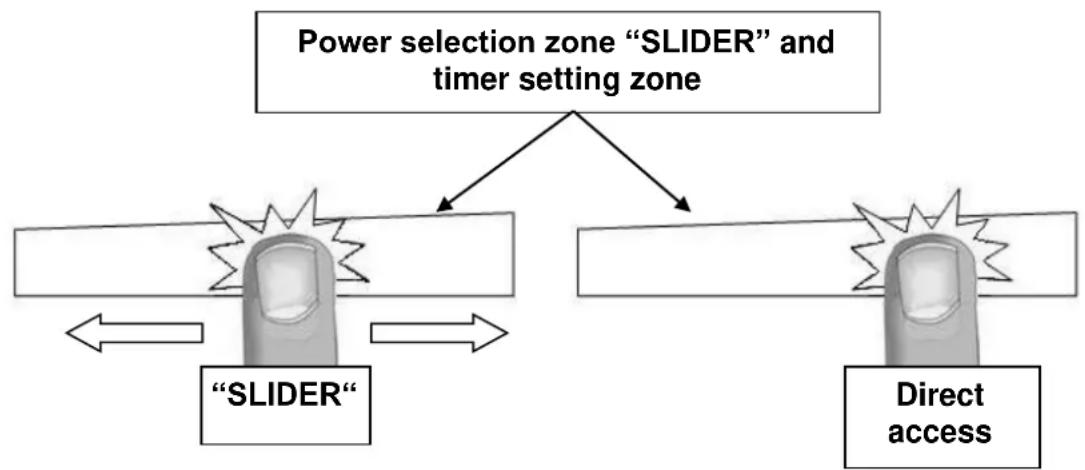
To select the power with the slider, slide your finger on the "SLIDER" zone. You can already have a direct access if you put your finger directly on the chosen level.
flowchart
graph TD
A["Power selection zone "SLIDER" and timer setting zone"] --> B["SLIDER"]
A --> C["Direct access"]
B <--> D["Power selection zone "SLIDER" and timer setting zone"]
C <--> E["Power selection zone "SLIDER" and timer setting zone"]
Starting-up
- Start up / switch off the hob:
| Action | Control panel | Display |
| To start | Press key [ ] for 2 sec. | [0] are blinking |
| To stop | Press key [ ] for 2 sec. | Nothing or [H] |
- Start up / switch off a heating zone:
| Action | Control panel | Display |
| Zone selection | Press [0] of the selected zone | [0] and control light on |
| To set | Slide on the “SLIDER” | [0] to [9] |
| (adjust the power) | to the right or to the left | |
| To stop | Slide to [0] on “SLIDER” | [0] or [H] |
| or press on [0] | [0] or [H] | |
If no action is made within 20 second the electronics returns in waiting position.
Pan detection
The pan detection ensures a perfect safety. The induction doesn't work:
- If there is no pan on the heating zone or if this pan is not adapted to the induction. In this case it is impossible to increase the power and the display shows [U]. This symbol disappears when a pan is put on the heating zone.
- If the pan is removed from the heating zone the operation is stopped. The display shows [U]. The symbol [U] disappears when the pan is put back to the heating zone. The cooking continues with the power level set before.
After use, switch the heat element off: don't let the pan detection [U] active.
Residual heat indication
After switching off of a heating zone or the complete stop of the hob, the heating zones are still hot and indicates [H] on the display.
The symbol [ H ] disappears when the heating zones may be touched without danger.
As far as the residual heat indicators are on, don't touch the heating zones and don't put any heat sensitive object on them. There are risks of burn and fire.
Power Booster and Double Power Booster function
The Power Booster function [P] grants a boost of power to the selected heating zone.
If this function is activated the heating zones work during 10 minutes with an ultra high power.
Power Booster is foreseen for example to heat up rapidly big quantities of water, like nuddles
- Start up / Stop the Power Booster function:
| Action | Control panel | Display | |
| Zone selection | Press key [0] from the zone | [0] and control light on Start up the Power Booster Press key [P] | [P] during 5 min |
| Stop the Power Booster | Slide on the “SLIDER” | [P] to [0] Or press [P] | [9] |
- Start up / Stop the Double Power Booster function:
| Action | Control panel | Display | |
| Selection of the zone | Press key [0] | [0] | |
| Start up Power Booster | Press key [P] | [P] | |
| Start up Double Power Booster | Re-press key [P] | [,, ,, and P] | |
| Stop the Double Power Booster | Press key [P] | [P] | |
| Stop booster | Slide on the “SLIDER” | [9] to [0] |
• Power management:
The hole cooking hob is equipped by a maximum of power. When the Power Booster function is activated, and not to exceed the maximum power, the electronic system orders to reduce automatically the power level of an other heating zone. The display is blinking on [9] during a few seconds and then shows the maximum of power allowed:
Heating zone selected The other heating zone: (example: power level 9)
[ P ] is displayed [ 9 ] goes to [ 6 ] or [ 8 ] depending the type of zone
Timer
The timer is able to be used simultaneous with all heating zones and this with different time settings (from 0 to 99 minutes) for each heating zone.
- Setting and modification of the cooking time :
Example for 16 minutes at power 7 :
| Action | Control panel | Display | |
| Zone selection | Press display [0] selected | [0] and control light on | |
| Select the power level | Slide on the “SLIDER” to [7] | [7] | |
| Select « Timer » | Press display [CL] | [00] | |
| Set the units | Slide on the “SLIDER” to [6] | [0 fixed] [6 blinking] | |
| Valid the units | Press display [06] | [0 blinking] [6 fixed] | |
| Set the tens | Slide on the “SLIDER” to [1] | [1 blinking] [6 fixed] | |
| Valid the tens | Press display [16] | [16] | |
The time is confirmed and the cooking starts.
• To stop the cooking time:
Example for 13 minutes at power 7 :
| Action | Control panel | Display | |
| Zone selection | Press display [7] selected | [0] and control light on | |
| Select « Timer » | Press key [13] | [13] | |
| Desactivate the units | Slide on the “SLIDER” to [0] | [1 fixed] [0 blinking] | |
| Valid the units | Press display [10] | [1 blinking] [0 fixed] | |
| Desactivate the tens | Slide on the “SLIDER” to [0] | [0 blinking] [0 fixed] | |
| Valid the tens | Press display [00] | [00] | |
• Automatic stop at the end of the cooking time:
As soon as the selected cooking time is finished the timer displays blink [00] and a sound rings.
To stop the sound and the blinking it is enough to press the key [00].
- Egg timer function :
Example for 29 minutes :
| Action | Control panel | Display | |
| Activate the hob | Press display [ 1 ] | Zone control lights are on | |
| Select« Timer » | Press display [ CL ] [ 00 ] | ||
| Set the units | Slide on the “SLIDER” to [ 9 ] [ 0 fixed ] [ 9 blinking ] | ||
| Valid the units | Press display [ 09 ] [ 0 blinking ] [ 9 fixed ] | ||
| Set the tens | Slide on the “SLIDER” to [ 2 ] | [ 2 blinking ] [ 9 fixed ] | |
| Valid the tens | Press display [ 29 ] [ 29 ] | ||
After a few seconds the control light stops blinking.
As soon as the selected cooking time is finished the timer displays blink [00] and a sound rings.
To stop the sound and the blinking it is enough to press the display [00]. The hob switches off.
Automatic cooking
All the cooking zones are equipped with an automatic cooking device. The cooking zone starts at full power during a certain time, then reduces automatically its power on the pre-selected level.
- Start-up :
Action Control panel Display
Zone selection Press display [0] selected [0] and control light on Full power setting Slide on the "SLIDER" to [9] Pass from [0] to [9] Automatic cooking Press on "SLIDER" [9] is blinking with [A] Power level selection Slide on the "SLIDER" to [7] [9] pass to [8] [7] (for example « 7 ») [7] is blinking with [A]
- Switching off the automatic cooking :
Action Control panel Display
Zone selection Press [7] from the zone [7] blinking with [A] Power level selection Slide on the "SLIDER" [1] to [9]
| Selected power | Automatic cooking time (Min:S) |
| 1 | 00:48 |
| 2 | 02:24 |
| 3 | 03:36 |
| 4 | 05:24 |
| 5 | 06:48 |
| 6 | 02:00 |
| 7 | 02:48 |
| 8 | 03:36 |
| 9 | -:- |
Stop&Go function
This function brakes all the hob's cooking activity temporarily and allows restarting with the same settings.
- Startup/stop the pause function :
Action Control panel Display
Engage pause press [ II ] key displays [ II ] in the during 2s heating zone displays Stop the pause press [ II ] key pause control light is during 2s blinking press an other touch or pause control light is off slide on the “SLIDER”
Recall Function
After switching off the hob (①), it is possible to recall the last settings.
• cooking stages of all cooking zones (power)
- minutes and seconds of programmed cooking zone-related timers
- Keep warm function
The recall procedure is following:
- Press the key [ ①]
- Then simultaneously press the 2 zones back in less than 6 seconds.
The previous settings are again active.
Bridge Function
This function allows to use the 2 cooking zones at same time with the same features as a single cooking zone. Power Booster function isn't allowed.
Action Control panel
Display
Activate the hob
Press display [ ① ]
[0] or [H] on the
4 displays
Activate the bridge
Press on the 2 cooking zones
[0] appears on the front
zone
[Π] on the rear zone.
Increase bridge
Slide on the "SLIDER" [1 to 9] or [U]
[ 1 to 9 ] or display [ keep warm ]
Stop the bridge
Press on the 2 cooking zones [0] or [H] on the 2
zones
This function allows to reach and maintain automatically a temperature of 70^ C.
This will avoid liquids overflowing and fast burning at the bottom of the pan.
| Action | Control panel | Display | |
| Zone selection | press display [0] selected | [0] to [9] or [H] | |
| To engage | press [Keep warm] on the “SLIDER” | [U] | |
| To stop | press on display [U] selected | [U] | |
| slide on the “SLIDER” | [0] to [9] or [H] |
This function can be started independently on all the heating zones.
When the pan leaves the cooking zone of the "Keep warm" function remains active during approximately 10 minutes.
The maximum duration of keeping warm is 2 hours.
Control panel Locking
To avoid modification of the setting of the cooking zones, in particular during cleaning, the control panel can be locked (with exception to the On/Off key [ ① ]).
- Lock :
Action
Control panel
Display
Start
Hob locking
press key for 2 sec. [①]
-
press simultaneously [P] and [0] from the front right zone display
-
re-press on [0] [L] on displays
[0] or [H] on displays
no modification
- Unlock :
Action Control panel
Display
Start
press key for 2 sec. [ ]
[L] on displays
In the 5 seconds after start:
Unlocking the hob
- press simultaneously [P] and [0] or [H] on displays
[ L ] from the front right zone
- press on key [P] no light on the displays
Power limitation configuration
Before you start the procedure:
- Disconnect the appliance from the electrical network by removing the fuse or turning the circuit breaker off
- Reconnect the table to the electrical network.
- It is necessary to start the procedure within 2 minutes after the connection of the hob to the electrical network.
- Do not press the [ ] key.
Modification of the limitation of power:
1) Press the key n°2 and hold down.
2) The symbol [•] will appear on each display
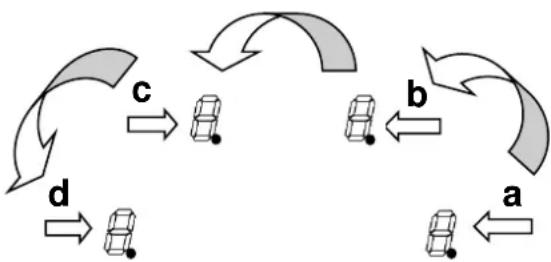
3) With your other hand, press successively and quickly (less than 2s) on each [•] display. Begin from the front right side and turn contrary clockwise as described on the picture (a -> b -> c -> d)).
A double "beep" means an error occurred. If so, start again from item 1).
flowchart
graph TD
    a --> b
    b --> c
    c --> d
    d --> a
    style a fill:#f9f,stroke:#333
    style b fill:#ccf,stroke:#333
    style c fill:#cfc,stroke:#333
    style d fill:#fcc,stroke:#333
4) Remove the fingers of the keys. In the back left display a "C" and a "0" appear flashing alternately. Meanwhile a standing "0" is displayed in the font left zone.
5) Select the back left key, then change "C0" in "C1" by means of position of your finger at the end of the "SLIDER".
6) Select the front left key.
7) Program the desired configuration wished by means of the "SLIDER", the beginning to decrease and the end to increase:
- 0 corresponds to 7400W
- 1 corresponds to 6800W
- 2 corresponds to 6000W
- 3 corresponds to 5400W
- 4 corresponds to 4800W
- 5 corresponds to 4600W
- 6 corresponds to 3700W
- 7 corresponds to 3000W
- 8 corresponds to 2400W
- 9 corresponds to 1900W
8) Select key n°1 during 2s to validate the configuration.
The total power of the hob when delivered is limited to 7400 W.
Maximum number of zones that can be activated simultaneously
The induction hob is preset at the factory. You can use the power limitation to change the value according to the electric requirements where the unit is to be installed. In order to not exceed this set value, the hob automatically distributes the power available between the cooking zones that are switched on. The appliance automatically regulates and selects the highest possible power level.
| Configuration | Pmax | Max number of zones |
| 0 | 7400 W | 4 |
| 1 | 6800 W | 4 |
| 2 | 6000 W | 4 |
| 3 | 5400 W | 4 |
| 4 | 4800 W | 4 |
| 5 | 4600 W | 3 |
| 6 | 3700 W | 3 |
| 7 | 3000 W | 2 |
| 8 | 2400 W | 2 |
| 9 | 1900 W | 1 |
Pan quality
Adapted materials: steel, enamelled steel, cast iron, ferromagnetic stainless-steel, aluminium with ferromagnetic bottom.
Not adapted materials: aluminium and stainless-steel without ferromagnetic bottom, cupper, brass, glass, ceramic, porcelain.
The manufacturers specify if their products are compatible induction.
To check if pans are compatibles:
- Put a little water in a pan placed on an induction heating zone set at level [9]. This water must heat in a few seconds.
• A magnet stucks on the bottom of the pan.
Certain pans can make noise when they are placed on an induction cooking zone. This noise doesn't mean any failure on the appliance and doesn't influence the cooking operating.
The composition of the pan base can affect the evenness of the cooking results and power reception by the inductors.
Only use pots and pans with smooth bases. Rough bases will scratch the ceramic glass.
Where possible, use pans with vertically straight side. If a pan has angular sides, induction also acts on the side of the pan. The sides of the pan may discolour.
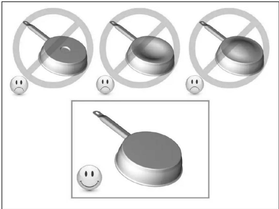
natural_image
Illustration of frying pan and cooking pan with no-smoking symbols, accompanied by sad face expressions (no text or labels)Pan dimension
The cooking zones are, until a certain limit, automatically adapted to the diameter of the pan. However the bottom of this pan must have a minimum of diameter according to the corresponding cooking zone.
To obtain the best efficiency of your hob, please place the pan well in the centre of the cooking zone.
Examples of cooking power setting
(the values below are indicative)
| 1 to 2 | MeltingReheating | Sauces, butter, chocolate, gelatineDishes prepared beforehand |
| 2 to 3 | SimmeringDefrosting | Rice, pudding, sugar syrupDried vegetables, fish, frozen products |
| 3 to 4 | Steam | Vegetables, fish, meat |
| 4 to 5 | Water | Steamed potatoes, soups, pasta,fresh vegetables |
| 6 to 7 | Medium cookingSimmering | Meat, lever, eggs, sausagesGoulash, roulade, tripe |
| 7 to 8 | Cooking | Potatoes, fritters, wafers |
| 9 | Frying, roostingBoiling water | Steaks, omelettes, fried dishesWater |
| P | Boiling water | scallops, steaksBoiling significant quantities of water |
MAINTENANCE AND CLEANING
Switch-off the appliance before cleaning.
Do not clean the hob if the glass is too hot because they are risk of burn.
- Remove light marks with a damp cloth with washing up liquid diluted in a little water. Then rinse with cold water and dry the surface thoroughly.
- Highly corrosive or abrasive detergents and cleaning equipment likely to cause scratches must be absolutely avoided.
- Do not ever use any steam-cleaner or pressure washer.
- Do not use any object that may scratch the ceramic glass.
- Ensure that the pan is dry and clean. Ensure that there are no grains of dust on your ceramic hob or on the pan. Sliding rough saucepans will scratch the surface.
- Spillages of sugar, jam, jelly, etc. must be removed immediately. You will thus prevent the surface being damaged.
WHAT TO DO IN CASE OF A PROBLEM
When the symbol [ E 4 ] appears :
- The table must be reconfigured. Please implement the following steps:
I) Important: before you start, make sure there is no more pot on the hob
II) Disconnect the appliance from the grid by removing the fuse or turning the circuit breaker off
III) Reconnect the table to the grid
IV) Procedure : take a pot with a ferromagnetic bottom and a minimum diameter of 16 cm
* start the procedure within 2 minutes after reconnecting the hob to the grid
* don't use the [0/l] touch
V) First step : cancel the existing configuration
1) Press the touch [ P ] and hold down
2) The symbol [ . ] will appear on each display
3) With your other hand, press successively and quickly (less than 2s) on each [ . ] display.
Begin from the front right side and turn contrary clockwise, as described on the picture (from a to d).
![BERTAZZONI P604IM2B2NE-20 - When the symbol [ E 4 ] appears : - 1](/content/2026/05/970987/images/18e8d7d72464d6de853a2da6a80f6913d74bcce1be0f792984dbcc615a24e128.jpg)
flowchart
graph TD
    A["a"] -->|双向箭头| B["b"]
    B -->|双向箭头| C["c"]
    C -->|双向箭头| D["d"]
    D -->|双向箭头| A
    style A fill:#f9f,stroke:#333
    style B fill:#f9f,stroke:#333
    style C fill:#f9f,stroke:#333
    style D fill:#f9f,stroke:#333
    style_E["△ P II"] --> F["△ P II"]
    style_G["%"] --> H["◀ u"]
A double "beep" means an error occurred. If so, start again from item 1).
4) Remove your fingers from the touch control, then push again on touch [0/I] during few seconds, until blinking [E] symbols appear.
5) Wait until [ E ] symbols stop blinking.
6) After few seconds, [ E ] are automatically transformed in [ C ]. The existing setup has been cancelled.
Note : For induction hobs with 3 cooking zones, as the right front zone doesn't exist in this case, begin the procedure with the right rear zone (b).
VI) Second step : new setup
1) Take a ferromagnetical pot with a minimum diameter of 16 cm
2) Select a cooking zone by pushing on the corresponding [ C ] display
3) Place the pot on the area to be set
4) Wait until the [ C ] display becomes a [ - ]. The selected cooking zone is now configured.
5) Follow the same procedure for each cooking zone with a [ C ] display.
6) All the cooking zones are configured once all the displays are turned off.
Please use the same pot for the whole procedure.
Never put several pots together on the zones during the setup-process.
- If [ E 4 ] displaying remains, please call the customer care
The hob or the cooking zone doesn't start-up:
- The hob is badly connected on the electrical network.
• The protection fuse cut-off. - The looking function is activated.
- The sensitive keys are covered of grease or water.
- An object is put on a key.
The control panel displays [U]:
- There is no pan on the cooking zone.
- The pan is not compatible with induction.
- The bottom diameter of the pan is too small.
The control panel displays [ E ]:
- Disconnect and replug the hob.
- Call the After-sales Service.
One or all cooking zone cut-off:
- The safety system functioned.
- You forgot to cut-off the cooking zone for a long time.
• One or more sensitive keys are covered. - The pan is empty and its bottom overheated.
- The hob also has an automatic reduction of power level and breaking Automatic overheating
Continuous ventilation after cutting off the hob:
- This is not a failure, the fan continuous to protect the electronic device.
- The fan cooling stops automatically.
The automatic cooking system doesn't start-up:
• The cooking zone is still hot [H].
- The highest power level is set [9].
The control panel displays [L]:
• Refer to the chapter control panel locking page.
The control panel displays [U]:
- Refer to the chapter "Keep warm".
The control panel displays [ II ]:
• Refer to the chapter "Pause".
The control panel displays [ ] or [ Er03 ] :
- An object or liquid covers the control keys. The symbol disappear as soon as the key is released or cleaned.
The control panel displays [E2] or [EH]:
- The hob is overheated, let it cool and then turn it onagain.
The control panel displays [ E3 ] :
- The pan is not adapted, change the pan.
The control panel displays [E6]:
- Defective network. Control the frequency and voltage of the electrical network.
The control panel displays [ E8 ] :
- The air inlet of the ventilator is obstructed, release it.
The control panel displays [ E C ] :
- Configuration error. Set the table again, referring to the chapter "The [E 4] appears."
If one of the symbols above persists, call the SAV.
ENVIRONMENT PRESERVATION
- The materials of packing are ecological and recyclable.
- The electronic appliances are composed of recyclable, and sometimes harmful materials for the environment, but necessary to the good running and the safety of the appliance.
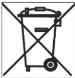
natural_image
Symbol of a trash bin crossed out by two diagonal lines (no text or labels)- Don't throw your appliance with the household refuses
- Get in touch with the waste collection centre of your commune that is adapted to the recycling of the household appliances.
INSTALLATION INSTRUCTIONS
The installation comes under the exclusive responsibility of specialists.
The installer is held to respect the legislation and the standards enforce in his home country.
How to stick the gasket:
The gasket supplied with the hob avoids all infiltration of liquids in the cabinet.
His installation has to be done carefully, in conformity of the following drawing.
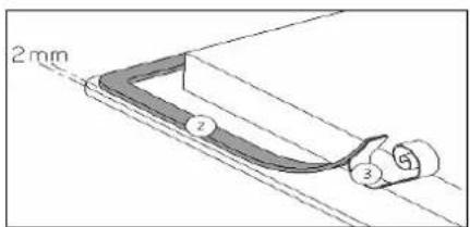
Stick the gasket (2) two millimeters from the external edge of the glass, after removing the protection sheet (3).
Fitting - installing:
The cut-out sizes are:
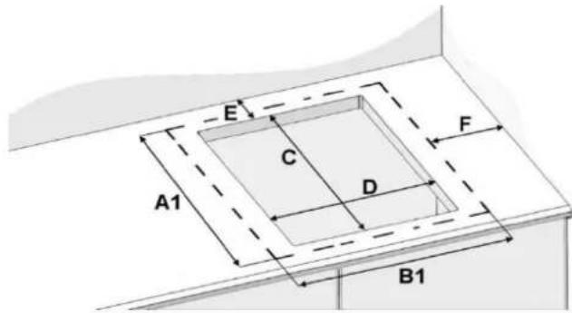
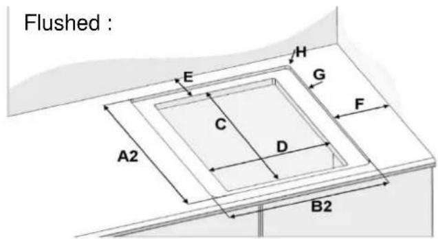
| Glass size | Cut-out size | Rear | Side | Radius | Cut size | Deep | ||||
| A1 | B1 | C | D | E | F | H | A2 | B2 | G | |
| P604IM2B2NE-20 | 520 | 590 | 490 | 560 | 50 | 40 | 8 | 526 | 596 | 5 |
- Ensure that there is a distance of 50 mm between the hob and the wall or sides.
- The hobs are classified as "Y" class for heat protection. Ideally the hob should be installed with plenty of space on either side. There may be a wall at the rear and tall units or a wall at one side. On the other side, however, no unit or divider must stand higher than the hob.
- The piece of furniture or the support in which the hob has to be fit, as well as the edges of furniture, the laminate coatings and the glue used to fix them, must be able to resist temperatures of up to 100 °C.
- The mural rods of edge must be heat-resisting.
- Not to install the hob to the top of a not ventilated oven or a dishwasher.
- The supporting countertop must be able to support the weight of the induction cooktop which is approximately 20kg.
- To ensure the induction cooktop adheres correctly to the countertop, after having applied the gasket/silicone, place evenly distributed weights on the cooktop (pots filled with water may be used).
- If a drawer is below the hob, to guarantee a good air circulation and good cooling system of the appliance, maintain a gap of 30 mm minimum between the bottom of the drawer and the inferior part of the hob.
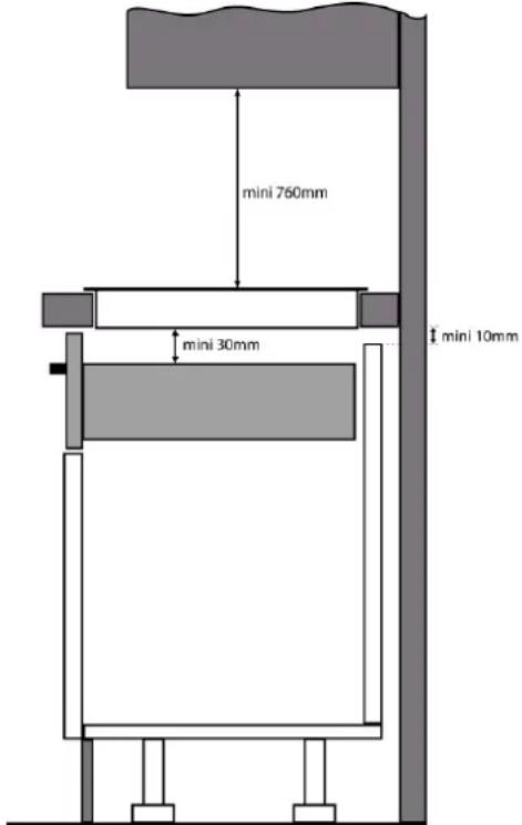
- If a drawer is placed under the hob, avoid to put into this drawer flammable objects (for example: sprays) or not heat-resistant objects.
- Materials often used to make worktops expand on contact with water. To protect the cut out edge, apply a coat of varnish or special sealant. Particular care must be given to applying the adhesive joint supplied with the hob to prevent any leakage into the supporting furniture. This gasket guarantees a correct seal when used in conjunction with smooth work top surfaces.
- The distance between the hob and the cooker hood placed above must respect the indications of the hood manufacturer. In case of absence of instructions respect a minimum distance of 760 mm.
- The connection cord should be subjected, after building, with no mechanical constraint, such for example of the fact of the drawer.
-
WARNING: Use only hob guards designed by the manufacturer of the cooking appliance or indicated by the manufacturer of the appliance in the instructions for use as suitable or hob guards incorporated in the appliance. The use of inappropriate guards can cause accidents.
-
The installation of this appliance and the connection to the electrical network should be entrusted only to an electrician perfectly to the fact of the normative regulations and which respects them scrupulously.
- Protection against the parts under tension must be ensured after the building-in.
- The data of connection necessary are on the stickers place on the hob casing near the connection box.
- If the supply cord is damaged, it must be replaced by the manufacturer, its service agent or similarly qualified persons in order to avoid a hazard.
- The connection to the main must be made using an earthed plug or via an omnipolar circuit breaking device with a contact opening of at least 3 mm.
- The electrical circuit must be separated from the network by adapted devices, for example: circuit breakers, fuses or contactors.
- If the appliance is not fitted with an accessible plug, disconnecting means must be incorporated in the fixed installation, in accordance with the wiring rules.
- The inlet hose must be positioned so that it does not touch any of the hot parts of the hob or even.
Caution!
This appliance has only to be connected to a network 230 V\~ 50/60 Hz.
Connect always the earth wire.
Respect the connection diagram.
The connection box is located underneath at the back of the hob casing. To open the cover use a medium screwdriver. Place it in the slits and open the cover.
CONNECTION OF THE HOB FOR :
| Mains | Connection | Supply cord | Supply cord | Circuit braker |
| 230V~ 50/60Hz | 1 Phase + N | 3 × 2,5 mm^2 | H 05 VV - FH 05 RR - F | 25 A * |
| 400V~ 50/60Hz | 2 Phases + N | 4 × 1.5 mm^2 | H 05 VV - FH 05 RR - F | 16 A * |
* calculated with the simultaneous factor following the standard EN 60 335-2-6
Connection of the hob
Setting up the configurations:
For the various kinds of connection, use the brass bridges which are in the box next the terminal
Monophase 230V\~1P+N
Put a bridge between terminal 1 and 2.
Attach the earth to the terminate “earth”, the neutral N to terminal 4, the Phase L to one of the terminals 1 or 2.
Biphase 400V\~2P+N
Attach the earth to the terminate “earth”, the neutral N to terminal 4, the Phase L1 to the terminals 1 and the Phase L2 to the terminal 2.
Caution! Be careful that the cables are correctly engaged and tightened.
We cannot be held responsible for any incident resulting from incorrect connection or which could arise from the use of an appliance which has not been earthed or has been equipped with a faulty earth connection.
SICUREZZA 24
PRECAUZIONI PER L'USO DEL DISPOSITIVO 24
USO DELL'APPARECCHIO 25
PRECAUZIONI CONTRO I DANNI....26
natural_image
Illustration of frying panes and a frying pan with sad face emojis, no text or symbols presentnatural_image
Symbol of a trash bin crossed out by diagonal lines, representing waste or disposal (no text or labels)
FONCTION STOP & GO....58
FONCTION RAPPEL 58
FONCTION BRIDGE 58
natural_image
Illustration of three frying pan icons with no accompanying text or symbols, accompanied by sad face emojis (no text or symbols present)natural_image
Symbol of a trash bin crossed with a diagonal line, representing no waste or disposal (no text or labels present)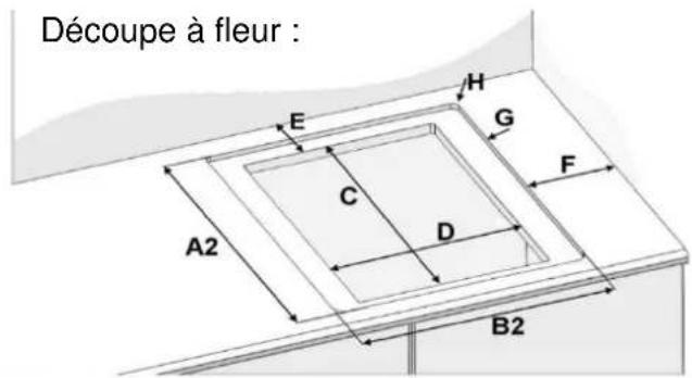
natural_image
Illustration of three frying panes with no stop sign, each accompanied by a sad face emoji (no text or symbols)natural_image
Symbol of a trash bin crossed with no text or labels, representing waste sorting or restriction (no text present)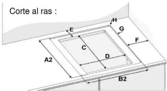
- DESCRIPTION OF THE APPLIANCE....7
- USE OF THE APPLIANCE......8
- STARTING-UP AND APPLIANCE MANAGEMENT 9
- COOKING ADVICES....16
- MAINTENANCE AND CLEANING....17
- WHAT TO DO IN CASE OF A PROBLEM....17
- ENVIRONMENT PRESERVATION 19
- INSTALLATION INSTRUCTIONS....20
- ELECTRICAL CONNECTION 22
- Precautions before usage
- Using the appliance
- Precautions to prevent damage to the appliance
- Precautions in case of appliance failure
- Other protections
- Control panel
- USE OF THE APPLIANCE
- Sensitive touch
- Display
- Ventilation
- Before the first use
- Induction principle
- Power selection zone "SLIDER" and timer setting zone
- Starting-up
- Pan detection
- Residual heat indication
- Power Booster and Double Power Booster function
- Timer
- Automatic cooking
- - Start-up :
- Action Control panel Display
- - Switching off the automatic cooking :
- Stop&Go function
- - Startup/stop the pause function :
- Recall Function
- Bridge Function
- Action Control panel
- Control panel Locking
- - Lock :
- Action
- - Unlock :
- In the 5 seconds after start:
- Power limitation configuration
- Before you start the procedure:
- Modification of the limitation of power:
- Maximum number of zones that can be activated simultaneously
- Pan quality
- Pan dimension
- Examples of cooking power setting
- MAINTENANCE AND CLEANING
- Switch-off the appliance before cleaning.
- WHAT TO DO IN CASE OF A PROBLEM
- When the symbol [ E 4 ] appears :
- The hob or the cooking zone doesn't start-up:
- The control panel displays [U]:
- The control panel displays [ E ]:
- One or all cooking zone cut-off:
- Continuous ventilation after cutting off the hob:
- The automatic cooking system doesn't start-up:
- The control panel displays [L]:
- The control panel displays [ II ]:
- The control panel displays [ ] or [ Er03 ] :
- The control panel displays [E2] or [EH]:
- The control panel displays [ E3 ] :
- The control panel displays [E6]:
- The control panel displays [ E8 ] :
- The control panel displays [ E C ] :
- If one of the symbols above persists, call the SAV.
- ENVIRONMENT PRESERVATION
- INSTALLATION INSTRUCTIONS
- How to stick the gasket:
- Fitting - installing:
- Caution!
- Connection of the hob
- SICUREZZA 24
Brand : BERTAZZONI
Model : P604IM2B2NE-20
Category : Cooker