
PR-38E - Drill HiKOKI - Free user manual and instructions
Find the device manual for free PR-38E HiKOKI in PDF.


| Product Type | Drill |
| Brand | HiKOKI |
| Model | PR-38E |
| Power Source | Corded electric |
| Power Input | 600 W |
| No-Load Speed | 0 – 2,800 RPM (variable) |
| Chuck Type | Keyless, 13 mm (1/2 in) |
| Drilling Capacity (Steel) | 13 mm |
| Drilling Capacity (Wood) | 25 mm |
| Dimensions (L x W x H) | 280 x 60 x 180 mm |
| Weight | 1.6 kg |
| Main Functions | Drilling, driving screws (with bit holder) |
| Speed Control | Variable speed trigger |
| Forward/Reverse | Yes |
| Ergonomic Grip | Soft grip handle |
| Maintenance | Regularly clean vents, lubricate chuck, inspect brush wear |
| Cleaning | Wipe with dry cloth; avoid solvents |
| Safety Features | Double insulation, lock-on button, safety guard |
| Spare Parts | Carbon brushes, chuck, switch, cord |
| Repairability | User-replaceable brushes; service center for others |
| Warranty | 1 year (check local) |
Frequently Asked Questions - PR-38E HiKOKI
User questions about PR-38E HiKOKI
0 question about this device. Answer the ones you know or ask your own.
Ask a new question about this device
Download the instructions for your Drill in PDF format for free! Find your manual PR-38E - HiKOKI and take your electronic device back in hand. On this page are published all the documents necessary for the use of your device. PR-38E by HiKOKI.
USER MANUAL PR-38E HiKOKI
Rotary Hammer Martillo perforador
手提電動鎚鑽

Read through carefully and understand these instructions before use.


10

11

12
13

14
15

16
17

| English Español | 中國語 | ||
| 1 | Tool Herramienta | 工具 | |
| 2 | Retainer Retenedor | 夾持器 | |
| 3 | Front cover Cubierta delantera | 前罩 | |
| 4 | Stopper Retén | 停止器 | |
| 5 | Plug Tapón | 塞子 | |
| 6 | Snap off this portion after driving in the self-drilling anchor. | Sacar esta parte luego de colocar el anclaje de autoperforación. | 打入自鑽錨栓後,將此部份卸掉。 |
| 7 | Turning handle Manija para girar | 轉動柄 | |
| 8 | Anchor adapter Adaptador de anclaje | 錨栓附加器 | |
| 9 | Striking by hammer drill Golpear con martillo | 用錘鑽錘擊 | |
| 10 | Move right and left. Mover a la derecha e izquierda | 左右搖動 | |
| 11 | Hole depth Profundidad del orifi cio | 孔深 | |
| 12 | Drift key Cuña saca mecha | 扳鍵 | |
| 13 | Wrench out Extraer | 扳出 | |
| 14 | Taper shank adapter Adaptador de la espiga ahusada | 錐柄附加器 | |
| 15 | Drill bit (with tapered shank) Broca de barrena (barrena ahusada) | 鑽頭(帶錐柄) | |
| 16 | Hole depth indicating groove: A standard depth conforming to the anchor outside diameter is indicated. | Ranura que indica la profundidad del orifi cio: Indica una profundidad estándar de acuerdo con el diámetro exterior del perno de anclaje. | 孔深標示槽:標示與錨栓直徑對應的標準深度。 |
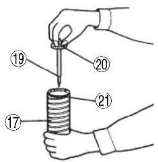
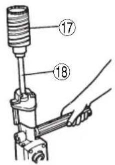
| 17 | Core bit Barrena tubular | 取心鑽具 | |
| 18 | Core bit shank | Espiga de la barrena tubular | 取心鑽柄 |
| 19 | Center pin | Pasador central | 中間銷 |
| 20 | Guide plate Placa guía | 導板 | |
| 21 | Core bit tip | Punta de barrena tubular | 取心鑽具尖端 |
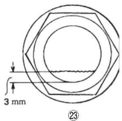
| 22 | Oil gauge Check the oil quantity by holding the body upright. | Indicador de aceite Compruebe la cantidad de aceite sujetando el cuerpo recto. | 油量計握住鑽機主體,使之朝上以檢查油量。 |
| 23 | Resupply oil when the oil level drops to less than approx. 3 mm. | Cuando el nivel de aceite disminuya a menos de unos 3 mm, rellene con aceite. | 油量降到約3 mm以下時,應即加以補充。 |
| 24 | Wear limit | Limite de desgaste | 磨損極限 |
| 25 | No. of carbon brush | No. de escobilla de carbón | 碳刷號 |
Read all instructions
Failure to follow all instructions listed below may result in electric shock, fire and/or serious injury.
The term “power tool” in all of the warnings listed below refers to your mains operated (corded) power tool or battery operated (cordless) power tool.
SAVE THESE INSTRUCTIONS
1) Work area
a) Keep work area clean and well lit.
Cluttered and dark areas invite accidents.
b) Do not operate power tools in explosive atmospheres, such as in the presence of fl ammable liquids, gases or dust.
Power tools create sparks which may ignite the dust of fumes.
c) Keep children and bystanders away while operating a power tool.
Distractions can cause you to lose control.
2) Electrical safety
a) Power tool plugs must match the outlet.
Never modify the plug in any way.
Do not use any adapter plugs with earthed (grounded) power tools.
Unmodifi ed plugs and matching outlets will reduce risk of electric shock.
b) Avoid body contact with earthed or grounded surfaces such as pipes, radiators, ranges and refrigerators.
There is an increased risk of electric shock if your body is earthed or grounded.
c) Do not expose power tools to rain or wet conditions.
Water entering a power tool will increase the risk of electric shock.
d) Do not abuse the cord. Never use the cord for carrying, pulling or unplugging the power tool.
Keep cord away from heat, oil, sharp edges or moving parts.
Damaged or entangled cords increase the risk of electric shock.
e) When operating a power tool outdoors, use an extension cord suitable for outdoor use.
Use of a cord suitable for outdoor use reduces the risk of electric shock.
3) Personal safety
a) Stay alert, watch what you are doing and use common sense when operating a power tool. Do not use a power tool while you are tired or under the influence of drugs, alcohol or medication.
A moment of inattention while operating power tools may result in serious personal injury.
b) Use safety equipment. Always wear eye protection.
Safety equipment such as dust mask, non-skid safety shoes, hard hat, or hearing protection used for appropriate conditions will reduce personal injuries.
c) Avoid accidental starting. Ensure the switch is in the off position before plugging in.
Carrying power tools with your finger on the switch or plugging in power tools that have the switch on invites accidents.
d) Remove any adjusting key or wrench before turning the power tool on.
A wrench or a key left attached to a rotating part of the power tool may result in personal injury.
e) Do not overreach. Keep proper footing and balance at all times.
This enables better control of the power tool in unexpected situations.
f) Dress properly. Do not wear loose clothing or jewellery. Keep your hair, clothing and gloves away from moving parts.
Loose clothes, jewellery or long hair can be caught in moving parts.
g) If devices are provided for the connection of dust extraction and collection facilities, ensure these are connected and properly used.
Use of these devices can reduce dust related hazards.
4) Power tool use and care
a) Do not force the power tool. Use the correct power tool for your application.
The correct power tool will do the job better and safer at the rate for which it was designed.
b) Do not use the power tool if the switch does not turn it on and off.
Any power tool that cannot be controlled with the switch is dangerous and must be repaired.
c) Disconnect the plug from the power source before making any adjustments, changing accessories, or storing power tools.
Such preventive safety measures reduce the risk of starting the power tool accidentally.
d) Store idle power tools out of the reach of children and do not allow persons unfamiliar with the power tool or these instructions to operate the power tool.
Power tools are dangerous in the hands of untrained users.
e) Maintain power tools. Check for misalignment or binding of moving parts, breakage of parts and any other condition that may affect the power tools' operation.
If damaged, have the power tool repaired before use.
Many accidents are caused by poorly maintained power tools.
f) Keep cutting tools sharp and clean.
Properly maintained cutting tools with sharp cutting edges are less likely to bind and are easier to control.
g) Use the power tool, accessories and tool bits etc., in accordance with these instructions and in the manner intended for the particular type of power tool, taking into account the working conditions and the work to be performed.
Use of the power tool for operations different from intended could result in a hazardous situation.
5) Service
a) Have your power tool serviced by a qualified repair person using only identical replacement parts.
This will ensure that the safety of the power tool is maintained.
PRECAUTION
Keep children and infi rm persons away.
When not in use, tools should be stored out of reach of children and infi rm persons.
ROTARY HAMMER SAFETY WARNINGS
1. Wear ear protectors.
Exposure to noise can cause hearing loss.
2. Use auxiliary handles supplied with the tool.
Loss of control can cause personal injury.
-
Wear protective glasses to protect your eyes.
-
Properly set the bit holder.
-
Do not touch the bit during or immediately after operation.
The bit becomes very hot during operation and could cause serious burns.
-
Safe operation depends on one's stable posture.
-
At the start of work, confirm the oil supply and screw tightening.
-
When working at a highly elevated location, pay attention to articles and persons below.
-
Before starting to break, chip or drill into a wall, floor or ceiling, thoroughly confi rm that such items as electric cables or conduits are not buried inside.
-
Wear a dust mask
Do not inhale the harmful dusts generated in drilling or chiseling operation. The dust can endanger the health of yourself and bystanders.
SPECIFICATIONS
| Model | PR-25B | PR-38E |
| Voltage (by areas)* | (110 V, 115 V, 120 V, 127 V, 220 V, 230 V, 240 V) ~ | |
| Power Input* | 1050 W | 1050 W |
| No-load speed | 750 /min. | 400 /min. |
| Full-load impact rate | 3000 /min. | 3000 /min. |
| Capacity: Drill bitCore bit | 25 mm64 mm | 38 mm105 mm |
| Weight (without cord) | 7.3 kg | 7.5 kg |
* Be sure to check the nameplate on product as it is subject to change by areas.
STANDARD ACCESSORIES
PR-25B
(1) Case 1
(2) Side handle....1
(3) Oil feeder 1
(4) Wrench 1
(5) Syringe....1
(6) Taper shank adapter 1
(7) Drill bit (tapered shank 14.5 mm)....1
(8) Cotter 1
PR-38E
(1) Case 1
(2) Side Handle 1
(3) Oil Feeder 1
(4) Wrench 1
Standard accessories are subject to change without notice.
OPTIONAL ACCESSORIES (sold separately)
○ Drill bit
(hexagonal shank, for drilling through-holes)

| Drill external diam. | Code No.(total length)(280 mm) | Code No.(total length)(505 mm) | |
| 16 mm | 944465 | 944470 | PR-25B PR-38E |
| 19 mm | 944466 | 944471 | |
| 22 mm | 944467 | 944472 | |
| 25 mm | 944468 | 944473 | |
| 28 mm | 944495 | 944496 | PR-38E |
| 32 mm | 944469 | 944474 | |
| 38 mm | 944545 | 944546 |
○ Drill bit
(tapered shank, for drilling anchor holes)

| Drill external diam. Code No. | |
| 11 mm 944460 | |
| 12 mm 944461 | |
| 14.3 mm 944462 | |
| 14.5 mm 944500 | PR-25Bstandard accessory |
| 17.5 mm 944463 | |
| 21.5 mm 944464 |
○ Taper shank adapter
(for installing taper shank drill)

| Drill diam.to be used | 11, 12, 14.3, 17.5 mm 21 | .5 mm |
| Code No. 944475 944476 | ||
○ Cotter (Code No. 944477)
(for taper shank adapter)

○ Core bit
(with guide plate, not applicable to cores 25 mm and 29 mm)


| Dø (mm) Code No. | ||
| 25 955994 | PR-25BPR-38E | |
| 29 955995 | ||
| 32 955996 | ||
| 35 955998 | ||
| 38 956000 | ||
| 45 955154 | ||
| 54 955155 | ||
| 64 956002 | ||
| 79 955157 | PR-38E94 95 | |
| 105 955159 | ||
○ Core bit shank

Code No. 955163
Applied to core bits above Dø 38 mm.
Code No. 956008
Applied to core bits below Dø 35 mm.
○ Center pin

Code No. 955165
Code No. 956009
for core bit Dø 32 mm and 35 mm
NOTE
Do not use it for core bit Dø 25 mm and 29 mm.
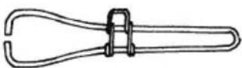
○ Drift key
(for self-drilling anchors)

(Code No. 944574)
○ Turning handle
(for self-drilling anchors)
(Code No. 944573)
○ Anchor adapter
(for self-drilling anchors)

NOTE
A turning handle is used with this anchor adapter.
| Anchor size | For rotation and impact | For impact |
| Code No. Code No. | ||
| w1/4 (No. 20) 94 | 4593 944568 | |
| w5/16 (No. 25) 94 | 44594 944569 | |
| w3/8 (No. 30) 94 | 4595 944570 | |
| w1/2 (No. 40) 94 | 4596 944571 | |
| w5/8 (No. 50) 94 | 4597 944572 | |
○ Bull point
(for crushing)

| Total length 280 mm 450 mm | |
| Code No. 944566 944583 |
○ Cold chisel
(for grooving and squaring)

| Total length 280 mm 450 mm | |
| Code No. 944567 944584 |
○ Syringe
(for removing chips after making holes)
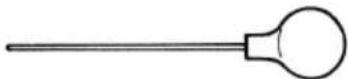
(Code No. 944575)
○ Cutter
(for crushing asphalt)

(Code No. 955180)
○ Rammer
(for tamping sand and gravel)
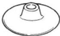
(Code No. 955181)
○ Bush hammer
(for roughing concrete and stone surfaces)
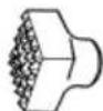
(Code No. 955183)
○ Shank
(for rammer and bush hammer)

(Code No. 955186)
- Bush hammer + Shank


- Rammer + Shank


○ Scoop
(for digging ground in various foundation work)

(Code No. 944967)
○ Rotary hammer oil (one liter)
(Code No. 955009)
Optional accessories are subject to change without notice.
APPLICATIONS
○ Drilling holes in concrete
○ Drilling anchor bolt holes
○ Crushing concrete, chipping, digging, and squaring (by applying optional accessories)
(Application Examples)
Installation of piping and wiring, sanitary facility installation, machinery installation, water supply and drainage work, interior jobs, harbor facilities and other civil engineering work.
PRIOR TO OPERATION
1. Power source
Ensure that the power source to be utilized conforms to the power requirements specified on the product nameplate.
2. Grounding
This tool should be grounded while in use to protect the operator from electric shock. The tool is equipped with a three conductor cord and grounding type plug to fit the proper grounding type receptacle. The green (or green and yellow) conductor in the cord is the grounding wire. Never connect the green (or green and yellow) wire to a live terminal.
3. Power switch
Ensure that the power switch is in the OFF position. If the plug is connected to a power receptacle while the power switch is in the ON position, the power tool will start operating immediately, which could cause a serious accident.
4. Extension cord
When the work area is removed from the power source, use an extension cord of sufficient thickness and rated capacity. The extension cord should be kept as short as practicable.
5. Feeding oil (refer to the paragraph on oil feeding, page 9)
Prior to using the power tool, remove the oil gauge and do not fail the oil tank with the provided oil. (Although the oil tank is built in, it contains only a small volume of oil when shipped from the HiKOKI Works.)
6. Mounting a tool
NOTE
When handling drill bits, bull point, cold chisel and other accessories, HiKOKI standard tools are recommended for better operation.
PR-25B
(1) Raise the retainer and insert the shank portion of a drill bit into the hexagonal hole on the front cover until it reaches the extremity. (Fig. 1-1)
(2) By slightly tapping the top of the bit holder with a wooden mallet, replace the bit holder to grip the bit firmly.
PR-38E
(1) Pushing the stopper to arrow A direction, turning the retainer to arrow B direction.
After, insert the tool shank into the hexagon hole on the front cover. (Fig. 1-2)
(2) Pushing the stopper to arrow A direction, turning the retainer to arrow B in the opposite direction. After, apart the stopper.
NOTE
When dismounting the bull points, reverse the procedures described above.
HOW TO USE THE ROTARY HAMMER
1. How to drill holes
(1) Pull the switch trigger after applying the drill bit tip to the drilling position.
(2) It is unnecessary to forcibly press the rotary hammer main body. It is sufficient to slightly press the rotary hammer to an extent that clips are freely discharged.
CAUTION
Although a safety clutch is built in this rotary hammer, the drill bit is suddenly halted when it strikes against a buried reinforcing bar, and the rotary hammer starts reverse operation as a reaction.
2. How to clip or crush
By applying the drill bit tip to the chipping or crushing position, operate the rotary hammer by utilizing its own weight.
Forcible pressing or thrusting is unnecessary.
DRILLING AND DRIVING-IN OPERATIONS FOR SELF-DRILLING ANCHORS
When self-drilling anchors (Fig. 4) are used, the anchors can be driven in. In this case, use the optional accessories for self-drilling anchor... such as the anchor adapter.
1. When an impact anchor adapter is used
(1) Attach the turning handle to the anchor adapter and create a base hole by applying Drill impact to the hole position while manually turning the handle. (Fig. 5) In this case, the plug is not attached to the anchor.
(2) When a predetermined depth has been attained, pull out the anchor tentatively. (Fig. 6)
(3) By employing a syringe, blow out the chips.
(4) Attach the plug to the anchor tip and drive in the anchor again with the rotary hammer.
(5) After driving in the anchor, use the drift key to separate the anchor. (Fig. 7)
(6) By employing a manual hammer or pliers, snap off the tapered portion of the anchor. (Fig. 8)
CAUTION
Since the snapped off tapered portion will fly about, pay attention to the snapping direction.
2. When a rotation and impact anchor adapter is used
(1) Attach a self-drilling anchor to the anchor adapter.
(2) Turn ON the switch and drill a base hole with the self-drilling anchor.
At the start of the hole-drilling slightly tilt the rotary hammer to determine the hole position.
(3) After clearing out dust with a syringe, attach the plug to the anchor tip and drive in the anchor with a hand hammer.
(4) For further operation, follow procedures (5) and (6) described above, when an impact anchor adapter is used.
3. When a taper shank adapter is used
(1) Attach a drill bit with tapered shank to the taper shank adapter.
(2) Turn ON the switch, and drill a hole until it reaches the hole depth indicating groove. (Fig. 9)
(3) After cleaning the dust with a syringe, attach a plug to the anchor tip and drive in the anchor with a manual hammer or pliers.
HOW TO HANDLE A CORE BIT
When a core bit is used, large caliber holes and blind holes can be drilled. In this case, use optional accessories for core bits (such as a center pin and core bit shank) for more rational operation.
1. Mounting
CAUTION
Prior to mounting a core bit, always disconnect the plug from the power supply receptacle.
(1) Mount the core bit on the core bit shank. (Fig. 10)
Before that, feed oil the screw portion of core bit shank for easily dismount.
(2) Mount the core bit shank on the main body in the same manner as in mounting the drill bit and the bull point. (Fig. 11).
(3) Insert the center pin into the guide plate until it reaches the extremity.
(4) Fit in the guide plate by aligning its concaved portion with the core bit tip. When the position of the concave is shifted by turning the guide plate right or left, the guide plate never slips off even when the rotary hammer is used in a downward direction. (Fig. 12)
2. Drilling holes
(1) Insert the plug into a power supply receptacle.
(2) A spring is built in the center pin. By straightly and gently pressing it to the wall or floor surface, the entire surface of the core bit tip attains contact to start the hole drilling job.
(3) When the hole depth reaches approximately 5 mm, the hole position can be determined.
Then remove the center pin and guide plate from the core bit and continue the hole drilling job.
CAUTION
When removing the center pin and guide plate, always disconnect the plug from the power supply receptacle.
3. How to dismount the core bit
(1) By holding the rotary hammer (with the core bit inserted) in an upward position. Drive the rotary hammer to repeat impact operation two or three times, whereby the screw is loosened and the rotary hammer becomes ready for disassembly.
(2) Remove the core bit shank from the rotary hammer, hold the core bit with one hand, and strongly strike the head of the hexagonal portion of the core bit shank with a hand hammer two or three times, whereby the round head screw is loosened and the rotary hammer l is ready for disassembly.
OIL FEEDING
CAUTION
Prior to oil feeding, always disconnect the plug from the power supply receptacle.
Since an oil chamber is built in this HiKOKI rotary hammer, it can be used for approximately 20 days without supplying lubricating oil, assuming that the Hammer is used continuously 3 – 4 hours daily.
Feed oil into the oil tank as described below before using this rotary hammer. (See Fig. 15 and 16)
- Just before no oil is visible in the oil gauge window when the device is held upright, feed oil without fail.
-
Before feeding oil, use the provided wrench to remove the oil gauge.
Be careful not to lose the rubber packing attached below the oil gauge. -
Check the oil level once daily, confirming that oil is filled.
-
After feeding oil, securely clamp the oil gauge.
NOTE
As an optional accessory, oil for the HiKOKI rotary hammer (one liter) is sold separately. Use this oil when oil in the tank is depleted. Shell Oil Co. ROTELLA #40 (engine oil) can also be used. This oil is sold as Shell fi lling stations most anywhere.
MAINTENANCE AND INSPECTION
1. Inspecting the drill bits
Since use of a dull tool will cause motor malfunctioning and degraded efficiency, replace the drill bit with new ones or resharpen them without delay when abrasion is noted.
2. Inspecting the mounting screws
Regularly inspect all mounting screws and ensure that they are properly tightened. Should any of the screws be loose, retighten them immediately. Failure to do so could result in serious hazard.
3. Maintenance of the motor
The motor unit winding is the very “heart” of the power tool. Exercise due care to ensure the winding does not become damaged and/or wet with oil or water.
4. Inspecting the carbon brushes (Fig. 17)
The motor employs carbon brushes which are consumable parts. Since an excessively worn carbon brush could result in motor trouble, replace the carbon brushes with new ones which having the same carbon brush No. shown in the figure when they become worn to or near the “wear limit”. In addition, always keep carbon brushes clean and ensure that they slide freely within the brush holders.
○ Replacement steps
The carbon brush can be removed by removing the tail cover and brush cap in that order at the interior.
5. Inspection of the dust cover
The dust cover functions as dust-proof of inside mechanism.
When the interior of the dust cover is worn, replace the new dust cover. The dust cover can be removed by pulling.
6. Service parts list
CAUTION
Repair, modification and inspection of HiKOKI Power Tools must be carried out by a HiKOKI Authorized Service Center.
This Parts List will be helpful if presented with the tool to the HiKOKI authorized Service Center when requesting repair or other maintenance.
In the operation and maintenance of power tools, the safety regulations and standards prescribed in each country must be observed.
MODIFICATION
HiKOKI Power Tools are constantly being improved and modified to incorporate the latest technological advancements.
Accordingly, some parts may be changed without prior notice.
NOTE
Due to HiKOKI's continuing program of research and development, the specifications herein are subject to change without prior notice.
(代號944574)
○ 轉動柄
(錨栓白鑽用)

(代號944573)
○ 錨栓附加器
(錨栓自鑽用)

註:
轉動柄與比錨栓附加器配合使用。
- 撞錘 + 柄

○鏟子
(各種基礎工程的挖土作業用)
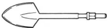
(代號944967)
○ 手提電動鎚鑽油(1升)
(代號955009)
選購附件可能不預先通告而徑予更改。
用途
○ 混凝土鑽孔
○ 鑽開錨栓孔
(رقم الكويت 944967)
(أ mythicalasted Adoption)
(944574 رقم الاكود)
PR-38E
| Item No. | Part Name Q'ty | |
| 84 | HEX. SOCKET HD.BOLT M5×14 | 4 |
| 86 | MACHINE SCREWM5×8 | 2 |
| 87 | SPRING WASHER M5 | 2 |
| 88B | HANDLE ANDHANDLE COVER SET | 1 |
| 89D | SWITCH (A) | 1 |
| 90F | SUPPORT (F) | 1 |
| 91 | CORD | 1 |
| 92 | CORD ARMOR | 1 |
| 93A | CORD CLIP | 1 |
| 94A | MACHINE SCREW(W/SP. WASHER)M4×8 | 1 |
| 95 | CONNECTOR 50092 | 2 |
| 96 | HANDLE COVER | 1 |
| 97 | CARBON BRUSH | 2 |
| 98 | BRUSH CAP | 2 |
| 99 | TAIL COVER 1 | |
| 100 | RIVET D2.5×4.8 | 2 |
| 101A | SIDE HANDLE | 1 |
| 102 | HEX. BARWRENCH 5MM | 1 |
| 103 | LUBRICANT OILER(120CC) | 1 |
| 104A | WRENCH 23MM 1 | |
| 105 | HEX. SOCKET SETSCREW M5×8 | 2 |
| 106B | CASE (PLASTIC) | 1 |
| 107 | NAME PLATE | 1 |
| 108 | CAUTION PLATE | 1 |
| 109A | FAN | 1 |
| 128 | HEX. SOCKET HD.BOLT M6×22 | 6 |
| 129A | TAPPING SCREW(W/FLANGE) D4×16 | 2 |
| 130 | HEX. SOCKET HD.BOLT (W/FLANGE)M6×22 | 4 |
| 131 | WASHER (A) | 1 |
| 132 | RETAINING RINGFOR D15 SHAFT | 1 |
| 133 | TAPPING SCREW(W/WASHER) D4×25 | 3 |
| 136 | NOISE SUPPRESSOR | 1 |
| 137 | INTERNAL WIRE | 1 |
| 138 | TUBE (D) | 2 |
| 139 | CONNECTOR 50091 | 1 |
| 140 | SUPPORT (B) | 1 |
| 142 | CONNECTOR 50092 | 2 |
| 143 | CHOKE COIL | 1 |
| Item No. | Part Name Q'ty | |
| 42 | BALL BEARING629VVC2PS2L | 1 |
| 43 | HEX. SOCKET HD.BOLT M6×45 | 4 |
| 45 | CONNECTING ROD ASS'Y | 1 |
| 46 | NEEDLE BEARING(NSK AJ50 1203) | 1 |
| 47 P | STON PIN | 1 |
| 48 P | STON | |
| 49A X | -RING | 1 |
| 50 S | TRIKER | |
| 51 | SEAL PACKING | 1 |
| 52 | CYLINDER CASE ASS'Y | 1 |
| 53 | METAL D12 ×20 | 1 |
| 54 | DRIVE SHAFT | 1 |
| 55 | BALL BEARING6001VVCMPS2L | 1 |
| 56 F | NAL PINION | 1 |
| 57 | WOODRUFF KEY3×10 | 1 |
| 58 | SPRING WASHER M8 | 1 |
| 59 U | NUT M8 | 1 |
| 60 | CYLINDER WASHER | 1 |
| 61 | URETHANE RING | 1 |
| 62 M | OUTH | 1 |
| 63 M | OUTH WASHER | 1 |
| 64 D | AMPER | 1 |
| 65 | BEARING WASHER | 1 |
| 66 F | NAL GEAR 1 | |
| 67 F | FRONT COVER | 1 |
| 68 D | UST COVER | 1 |
| 69 | HEX. SOCKET HD.BOLT M6×25 | 4 |
| 71 RETAINER | ||
| 72 | RETAINER ROD (A) ASS'Y | 1 |
| 72A | RETAINER ROD (A) | 1 |
| 73 | DAMPER (B) | 2 |
| 74 | WASHER M8 2 | |
| 75A | SPRING | 2 |
| 76 | STOPPER (L) | 1 |
| 77 | NEEDLE ROLLER | 2 |
| 78 | STOPPER RING | 2 |
| 79B | RETAINER ROD (B) ASS'Y | 1 |
| 79C | RETAINER ROD (B) | 1 |
| 80A | STOPPER (L) | 1 |
| 81 | STOPPER WASHER | 2 |
| 82A | COVER SEAL | 1 |
| 83A | COVER PLATE | 1 |
| Item No. | Part Name Q'ty | |
| 1A HOUSING ASS'Y 1 | ||
| 2 BRUSH HOLDER 2 | ||
| 3 STATOR ASS'Y 1 | ||
| 4 BRUSH TERMINAL 2 | ||
| 5 | MACHINE SCREW M5×55 | 2 |
| 6 | SPRING WASHER M5 | 2 |
| 7 | VINYL TUBE (I.D.9×T0.5×65) | 1 |
| 8 STOP PLATE 2 | ||
| 9A ARMATURE ASS'Y 1 | ||
| 10A | BALL BEARING 6000DDWCMNS7L | 1 |
| 11 DUST SEAL 1 | ||
| 12 | GEAR COVER ASS'Y | 1 |
| 13 DUST SEAL 1 | ||
| 14A | BALL BEARING 6202DDWCMNS7L | 1 |
| 15 | NEEDLE BEARING (M661) | 2 |
| 16 SIDE COVER 1 | ||
| 17 | CRANK CASE ASS'Y | 1 |
| 18B COVER SEAL (B) 1 | ||
| 19B COVER PLATE (B) 1 | ||
| 20 | MACHINE SCREW M4×12 | 6 |
| 21 | SPRING WASHER M4 | 6 |
| 22 OIL FELT 1 | ||
| 23 | MACHINE SCREW M4×12 | 7 |
| 24 | SPRING WASHER M4 | 5 |
| 25B | CRANK SHAFT ASS'Y | 1 |
| 26 | BALL BEARING 6204DDCMPS2L | 1 |
| 27 | BEARING COVER (B) | 1 |
| 28 FIRST GEAR 1 | ||
| 29A | FEATHER KEY 3×3×12 | 1 |
| 30 | HEX. SOCKET HD. BOLT M5×16 | 4 |
| 32 OIL GAUGE | 1 | |
| 33 SECOND SHAFT | 1 | |
| 34A BEVEL GEAR | 1 | |
| 35 CLUTCH PLATE | 2 | |
| 36 SECOND GEAR | 1 | |
| 37 SLIP PLATE (B) | 2 | |
| 38 | BELLEVILLE SPRING | 1 |
| 39 U-NUT M12 | 1 | |
| 40 | BEARING WASHER (C) | 1 |
| 41 | BEARING WASHER (B) | 1 |

Koki Holdings Co., Ltd.
806
Code No. C99014636 N
Printed in Japan

- ROTARY HAMMER MARTILLO PERFORADOR
- READ ALL INSTRUCTIONS
- SAVE THESE INSTRUCTIONS
- WORK AREA
- ELECTRICAL SAFETY
- PERSONAL SAFETY
- POWER TOOL USE AND CARE
- SERVICE
- PRECAUTION
- ROTARY HAMMER SAFETY WARNINGS
- WEAR EAR PROTECTORS
- USE AUXILIARY HANDLES SUPPLIED WITH THE TOOL
- STANDARD ACCESSORIES
- OPTIONAL ACCESSORIES (SOLD SEPARATELY)
- NOTE
- ○ SHANK
- ○ SCOOP
- APPLICATIONS
- PRIOR TO OPERATION
- POWER SOURCE
- GROUNDING
- POWER SWITCH
- EXTENSION CORD
- FEEDING OIL (REFER TO THE PARAGRAPH ON OIL FEEDING, PAGE 9)
- MOUNTING A TOOL
- PR-25B
- PR-38E
- HOW TO USE THE ROTARY HAMMER
- HOW TO DRILL HOLES
- CAUTION
- HOW TO CLIP OR CRUSH
- DRILLING AND DRIVING-IN OPERATIONS FOR SELF-DRILLING ANCHORS
- WHEN AN IMPACT ANCHOR ADAPTER IS USED
- WHEN A ROTATION AND IMPACT ANCHOR ADAPTER IS USED
- WHEN A TAPER SHANK ADAPTER IS USED
- HOW TO HANDLE A CORE BIT
- MOUNTING
- DRILLING HOLES
- HOW TO DISMOUNT THE CORE BIT
- OIL FEEDING
- MAINTENANCE AND INSPECTION
- INSPECTING THE DRILL BITS
- INSPECTING THE MOUNTING SCREWS
- MAINTENANCE OF THE MOTOR
- INSPECTING THE CARBON BRUSHES (FIG. 17)
- INSPECTION OF THE DUST COVER
- SERVICE PARTS LIST
- MODIFICATION
- ○ 轉動柄
- ○ 錨栓附加器
- ○鏟子
- 用途
- KOKI HOLDINGS CO., LTD
Brand : HiKOKI
Model : PR-38E
Category : Drill