
CSM-32 - Blender JBL - Free user manual and instructions
Find the device manual for free CSM-32 JBL in PDF.


| Product Type | Blender |
| Brand | JBL |
| Model | CSM-32 |
| Power Consumption | 500 W |
| Voltage | 120-240 V, 50-60 Hz |
| Jar Capacity | 1.5 L |
| Jar Material | BPA-free plastic |
| Blade Material | Stainless steel |
| Speed Settings | 2 speeds + Pulse |
| Safety Lock | Lid lock mechanism |
| Non-Slip Feet | Yes |
| Cord Length | 1.0 m |
| Weight | 3.5 kg |
| Dimensions (L x W x H) | 20 x 20 x 40 cm |
| Dishwasher Safe Jar | Yes (top rack) |
| Warranty | 2 years |
Frequently Asked Questions - CSM-32 JBL
User questions about CSM-32 JBL
0 question about this device. Answer the ones you know or ask your own.
Ask a new question about this device
Download the instructions for your Blender in PDF format for free! Find your manual CSM-32 - JBL and take your electronic device back in hand. On this page are published all the documents necessary for the use of your device. CSM-32 by JBL.
USER MANUAL CSM-32 JBL
CSM-21 & CSM-32 User Guide
This guide does not include all of the details of design, production, or variation of the equipment. Nor does it cover every possible situation which may arise during installation, operation or maintenance.
The information provided in this manual was deemed accurate as of the publication date. However, updates to this information may have occurred.
Trademark Notice: JBL is registered trademark of Harman International Industries, Incorporated. Other trademarks are the property of their respective owners.
© 2011 JBL Incorporated, 8400 Balboa Blvd. Northridge, CA 91329 USA. All Rights Reserved.
Contents
Important Safety Instructions ....2
Quick Start 4
1.0 Introduction......5
1.1 JBL Commercial CSM-21/CSM-32 Mixer....5
1.2 Other Mixer Features....5
2.0 Installation....6
2.1 Unpacking 6
2.2 Mechanical Requirements....6
2.3 Installing the Mixer 6
2.4 Audio Input and Output Wiring Convention....7
2.5 Using Optimal Settings When Working with CSA-2120 Amplifiers....7
3.0 Rear Panel 8
4.0 Front Panel ....11
5.0 Knowing Your Mixer 13
5.1 Source 13
5.2 Zones 13
5.3 Volume 13
5.4 AutoWarmth™ 13
5.5 LevelGuard™ 13
6.0 Setup 14
6.1 Determining Source Priorities....14
6.2 Connecting Sources ....14
6.3 Adjusting Source Gain ....14
6.4 Using EQ 14
6.5 Using Subwoofer Crossover ....15
6.6 Setting Up AutoWarmth™ Method 1 ....15
6.7 Setting Up AutoWarmth™ Method 2 ....15
6.8 Setting Up LevelGuard™ 16
6.9 Security Cover 16
Appendix A: Optional Item - CSR Series Remote Controls....17
Appendix B: Applications....18
Appendix C: Block Diagrams....21
Appendix D: Specifications....22
Appendix E: Contact Information....24
IMPORTANT SAFETY INSTRUCTIONS



ATTENTION: RISQUEDECHOCELECTRIQUE-NEPASOUVRIR
WARNING: TO REDUCETHERISKOFFIREORELECTRIC SHOCKDO NOT EXPOSETHISEQUIPMENTTORAINORMOISTURE
The symbols shown above are internationally accepted symbols that warn of potential hazards with electrical products. The lightning flash with arrowpoint in an equilateral triangle means that there are dangerous voltages present within the unit. The exclamation point in an equilateral triangle indicates that it is necessary for the user to refer to the owner's manual.
These symbols warn that there are no user serviceable parts inside the unit. Do not open the unit. Do not attempt to service the unit yourself. Refer all servicing to qualified personnel. Opening the chassis for any reason will void the manufacturer's warranty. Do not get the unit wet. If liquid is spilled on the unit, shut it off immediately and take it to a dealer for service. Disconnect the unit during storms to prevent damage.
SAFETY INSTRUCTIONS
NOTICE FOR CUSTOMERS IF YOUR UNIT IS EQUIPPED WITH A POWER CORD.
WARNING: THIS APPLIANCE SHALL BE CONNECTED TO A MAINS SOCKET OUTLET WITH A PROTECTIVE EARTHING CONNECTION.
The cores in the mains lead are coloured in accordance with the following code:
GREEN and YELLOW - Earth BLUE - Neutral BROWN - Live
As colours of the cores in the mains lead of this appliance may not correspond with the coloured markings identifying the terminals in your plug, proceed as follows:
- The core which is coloured green and yellow must be connected to the terminal in the plug marked with the letter E, or with the earth symbol, or coloured green, or green and yellow.
- The core which is coloured blue must be connected to the terminal marked N or coloured black.
- The core which is coloured brown must be connected to the terminal marked L or coloured red.
This equipment may require the use of a different line cord, attachment plug, or both, depending on the available power source at installation. If the attachment plug needs to be changed, refer servicing to qualified service personnel who should refer to the table below. The green/yellow wire shall be connected directly to the units chassis.
| CONDUCTOR | WIRE COLOR | ||
| Normal Alt | |||
| L LIVE | BROWN BLACK | ||
| N NEUTRAL BLUE WHITE | |||
| E | EARTH GND | GREEN/YEL | GREEN |
WARNING: If the ground is defeated, certain fault conditions in the unit or in the system to which it is connected can result in full line voltage between chassis and earth ground. Severe injury or death can then result if the chassis and earth ground are touched simultaneously.
WARNING FOR YOUR PROTECTION READ THE FOLLOWING:
KEEP THESE INSTRUCTIONS
HEED ALL WARNINGS
FOLLOW ALL INSTRUCTIONS
THE APPARATUS SHALL NOT BE EXPOSED TO DRIPPING OR SPLASHING LIQUID AND NO OBJECT FILLED WITH LIQUID, SUCH AS VASES, SHALL BE PLACED ON THE APPARATUS
CLEAN ONLY WITH A DRY CLOTH.
DO NOT BLOCK ANY OF THE VENTILATION OPENINGS. INSTALL IN ACCORDANCE WITH THE MANUFACTURER'S INSTRUCTIONS.
DO NOT INSTALL NEAR ANY HEAT SOURCES SUCH AS RADIATORS, HEAT REGISTERS, STOVES, OR OTHER APPARATUS (INCLUDING AMPLIFIERS) THAT PRODUCE HEAT.
ONLY USE ATTACHMENTS/ACCESSORIES SPECIFIED BY THE MANUFACTURER.
UNPLUG THIS APPARATUS DURING LIGHTNING STORMS OR WHEN UNUSED FOR LONG PERIODS OF TIME.
Do not defeat the safety purpose of the polarized or grounding-type plug. A polarized plug has two blades with one wider than the other. A grounding type plug has two blades and a third grounding prong. The wide blade or third prong are provided for your safety. If the provided plug does not fit your outlet, consult an electrician for replacement of the obsolete outlet.
Protect the power cord from being walked on or pinched particularly at plugs, convenience receptacles, and the point where they exit from the apparatus.
Use only with the cart stand, tripod bracket, or table specified by the manufacture, or sold with the apparatus. When a cart is used, use caution when moving the cart/apparatus combination to avoid injury from tip-over. Refer all servicing to to qualified service personnel. Servicing is required when the apparatus

has been damaged in any way, such as power-supply cord or plug is damaged, liquid has been spilled or objects have fallen into the apparatus, the apparatus has been exposed to rain or moisture, does not operate normally, or has been dropped.
POWER ON/OFF SWITCH: For products provided with a power switch, the power switch DOES NOT break the connection from the mains.
MAINS DISCONNECT: The plug shall remain readily operable. For rack-mount or installation where plug is not accessible, an all-pole mains switch with a contact separation of at least 3 mm in each pole shall be incorporated into the electrical installation of the rack or building.
FOR UNITS EQUIPPED WITH EXTERNALLY ACCESSIBLE FUSE RECEPTACLE: Replace fuse with same type and rating only.
MULTIPLE-INPUT VOLTAGE: This equipment may require the use of a different line cord, attachment plug, or both, depending on the available power source at installation. Connect this equipment only to the power source indicated on the equipment rear panel. To reduce the risk of fire or electric shock, refer servicing to qualified service personnel or equivalent.
If connected to 240V supply, a suitable CSA/UL certified power cord shall be used for this supply.
IMPORTANT SAFETY INSTRUCTIONS
DECLARATION OF CONFORMITY
Manufacturer's Name: JBL Professional
Manufacturer's Address: 8760 S. Sandy Parkway
Sandy, Utah 84070, USA
declares that the product:
Product name: JBL CSM-21, CSM-32
Note: Product name may be suffixed by the EU.
Product option: None
conforms to the following Product Specifications:
Safety: IEC 60065 -01+Amd 1
EMC: EN55022:2006
EN55024: 1998+A1:2001+A2:2003
FCC Part 15 Subpart B
ICES-003
Supplementary Information:
The product herewith complies with the requirements of the:
Low Voltage Directive 2006/95/EC
EMC Directive 2004/108/EC.
RoHS Directive 2002/95/EC
WEEE Directive 2002/96/EC
With regard to Directive 2005/32/EC and EC Regulation 1275/2008 of 17
December 2008, this product is designed, produced, and classified as Professional Audio Equipment and thus is exempt from this Directive.
Roger Johnsen
Director, Engineering
Signal Processing
8760 S. Sandy Parkway
Sandy, Utah 84070, USA
Date: January 28, 2011
European Contact: Your local JBL Sales and Service Office or
Harman Signal Processing
8760 South Sandy Parkway
Sandy, Utah
84070 USA
Ph: (801) 566-8800
Fax: (801) 568-7583
U.K. MAINS PLUG WARNING
A molded mains plug that has been cut off from the cord is unsafe. Discard the mains plug at a suitable disposal facility. NEVER UNDER ANY CIRCUMSTANCES SHOULD YOU INSERT A DAMAGED OR CUT MAINS PLUG INTO A 13 AMP POWER SOCKET. Do not use the mains plug without the fuse cover in
ELECTROMAGNETIC COMPATIBILITY
This device complies with part 15 of the FCC Rules and the Product Specifications noted on the Declaration of Conformity. Operation is subject to the following two conditions:
• this device may not cause harmful interference, and
- this device must accept any interference received, including interference that may cause undesired operation.
Operation of this unit within significant electromagnetic fields should be avoided.
• use only shielded interconnecting cables.
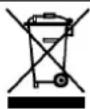
If you want to dispose this product, do not mix it with general household waste. There is a separate collection system for used electronic products in accordance with legislation that requires proper treatment, recovery and recycling.
Private household in the 25 member states of the EU, in Switzerland and Norway may return their used electronic products free of charge to designated collection facilities or to a retailer (If you purchase a similar new one).
For Countries not mentioned above, please contact your local authorities for a correct method of disposal.
By doing so you will ensure that your disposed product undergoes the necessary treatment, recovery and recycling and thus prevent potential negative effects on the environment and human health.
Quick Start
- Connect the included JBL power supply to the POWER jack on the rear panel of the mixer and check that it powers up.
- Switch on the POWER button on the front panel of the mixer.
- Connect a Left/Right RCA audio source to SOURCE 1 input. Do not put any audio through the unit at this time.
- Turn the SOURCE 1 GAIN knob on the rear panel of the unit all the way counter-clockwise.
- Turn the ZONE 1 LEVEL knob on the front panel all the way counter-clockwise.
- On the front panel, select source 1 with the ZONE 1 SELECT knob.
- Connect the ZONE 1 output on the rear panel to your power amplifier. Make sure the amplifier you are connecting to is not powered up while making this connection, this will prevent any nasty pops.
- Turn on your power amplifier.
- Turn on your audio source.
- Slowly turn up SOURCE 1 GAIN knob on the rear panel until the SIGNAL LED is showing constant green.
- Now turn up the source level by rotating the ZONE 1 LEVEL knob on the front panel until you hear audio through your source speakers.
- Adjust EQ to sound right in the room.
- See page 14 to 15 for setting AutoWarmth™ and LevelGuard™.
1.0 Introduction
1.1 JBL Commercial CSM-21 and CSM-32 Mixer
The JBL Commercial ® CSM-21 and CSM-32 mixers (hereafter called mixer) are specifically designed for flexible routing and control of multiple audio sources. To facilitate this, JBL has equipped the mixer with a wide array of input and output capabilities.
These features allow you to bring the same audio quality that many of your patrons are used to hearing at home into the realm of business. The mixers have been designed to make them easier to operate than any other product in their class. In reality, the feature set provided by the mixers put them in a class by themselves.
CSM-32 mixers provide 3 channel stereo inputs and 2 zone full range stereo outputs, and are equipped with functional connectors that provide connections to your microphones, direct input (fire alarm system), auxiliary devices, and CSR remote controls. CSM-21 mixers provide 2 channel stereo input, 1 zone full range stereo output, and are equipped with functional connectors that provide connections to microphones, direct input (fire alarm system), and CSR remote controls. For details about connectors and controls of mixes, refer to later chapters in this guide.
JBL's AutoWarmth™ and LevelGuard™ controls give you excellent sounding, easy to use equalization and dynamics control. This function allows the signal to be tailored for a wide variety of rooms, taste, and volume requirements.
1.2 Other Mixer Features
The mixers also feature linking capability. This is accomplished by connecting standard category 5 UTP cables to the mixer's LINK jacks.
Linking of multiple mixers provides additional output zones yet does not increase the number of inputs. SOURCES linking simply allows multiple mixers to share the same input source, eliminating the need for Y-cables. MAIN linking allows multiple mixers to share MIC input, MUSIC MUTE, and DIRECT INPUT functions. When multiple units are linked, there is no master or slave designation. The functions are simply paralleled so that sources, MIC input, MUSIC MUTE, and DIRECT INPUT can be run into any of the linked mixers.
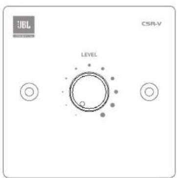
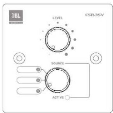
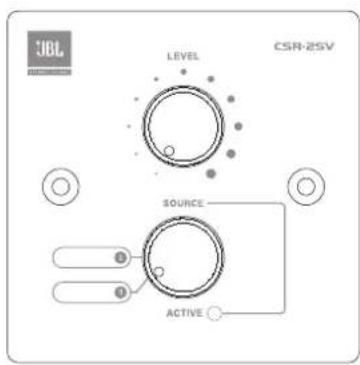
JBL offers several optional remote controls: CSR-V, CSR-2SV, and CSR-3SV. These remote controls provide remote source selection and/or volume adjustments within a zone location.
2.0 Installation
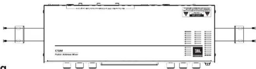
Method 1 - Attaching the brackets to the front panel for rack mounting

Method 2 - Attaching the brackets to the sides of the unit for wall mounting
2.1 Unpacking
This product is carefully checked before packing to ensure flawless appearance and operation and that it reaches you in first class condition.
Please unpack and inspect your mixer for any damage that may have occurred during transit. If damage is found, notify the transportation company immediately. Only you can initiate a claim for shipping damage. We will be happy to help as needed. Save the shipping carton as evidence of damage for the shipper's inspection.
We also recommend that you save all packing materials so you will have them if you ever need to transport the unit. Never ship the unit without the factory pack.
2.2 Mechanical Requirements
Adequate ventilation must be provided by allowing sufficient space around the sides, top, and rear of the mixer to ensure free circulation of air. Forced cooling is not required. The mixer requires a vertical rack space of 1U. Failure to do so may damage the mixer and invalidate the warranty.
2.3 Installing the Mixer
CAUTION: Before you begin, make sure that your mixer is disconnected from the power source and all level controls are turned completely down (counter-clockwise).
To install the mixer, you can use one of the following approaches:
• Use the original brackets come with the mixer.
1. Align holes of a bracket with the holes on the case.
2. Fasten the bracket with the provided screws.
3. Follow step 1 to 2 to install rest bracket(s) to the case according your application.
4. Install the assembly into the cabinet. For details of installation in the chassis of the cabinet, refer to the user guide of your cabinet.
• Install the mixer to the wall. See the Method 2 in the above figure.
• Stack amps without using a cabinet.
NOTE: When transporting, the mixer should be supported at both front and back.
2.4 Audio Input and Output Wiring Convention
Balanced wiring - The convention for balanced wiring (2-wire plus shield) is:

Unbalanced wiring - The convention for unbalanced wiring to the inputs (1-wire plus shield) is:
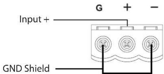
NOTE: The above wiring conventions are applicable for the following connectors: MIC INPUT, DIRECT INPUT, ISO AUX OUTPUT and ZONE OUTPUT.
2.5 Using Optimal Settings When Working with CSA-2120 Amplifiers
When working with the default level settings of CSA-2120 amplifiers, to optimize the volume performance of the mixer and CSA-2120 amplifiers, you are recommended to use the following settings:
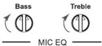
- Set the Bass and Treble trim pots on the front panel of the mixer to the vertical positions, as shown below:
- Set the MIC gain trim pot on the rear panel of the mixer to the optimal level as shown below:

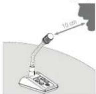
- Maintain a gap around 10 cm between the speaker's mouth and the microphone.
3.0 Rear Panel
CSM-32 illustration

CSM-21 illustration

1. Power Supply Input
Connect your included JBL power supply here.
2. Firmware Update
The USB connector allows you to connect your computer to the mixer and update the firmware of the mixer.
You can know the version of this firmware by observing the LEDs on the rear panel during the mixer booting process. The LED in SOURCE 1 section indicates major. The LED in SOURCE 2 section indicates minor. The LED in SOURCE 3 section indicates build. The LED beside MIC connector indicates revision. Each LED will flash in green once or more times for the numeral it stands for. The format is "major.minor[.build[.revision]]". For example, if the first released version is "v1.0.0.0", when you switch on the mixer, the LED in SOURCE 1 section will flash once, and the rest LEDs will turn red directly. Then the unit is ready for use.
3. Crossover
This switch activates the ZONE output 125 Hz crossover functionality on the left, right, and subwoofer outputs. When the crossover is “in”, the left and right outputs will allow frequencies above 125Hz to pass. The subwoofer output will allow frequencies below 125 Hz to pass. When the crossover is “out”, the left, right, and subwoofer outputs will pass full-range audio to allow the end-user to utilize the built-in crossover functionality on their speakers if desired. Use this crossover if the bass response of your room is too boomy, when you are using inexpensive loudspeaker transformers or in conjunction with the subwoofer crossover (see subwoofer crossover section).
4. Zone Output(s)
The mixer outputs utilize balanced Euroblock connectors. These outputs carry the Left, Right, and Subwoofer signals. Connect these to your zone power amplifier.
5. AutoWarmth™ Indicator and Trim Pot
These indicators flash green when the AutoWarmth function is being activated. This trim pot adjusts at what point AutoWarmth ™ is engaged.
6. Zone Remote Jacks
These inputs are for the optional remote controls: CSR-V, CSR-2SV, and CSR-3SV.
7. Isolated Auxiliary Output*
This sends a transformer isolated mono signal for a music-on-hold system, or for a separate mono auxiliary zone. The +/- outputs are 600 Ohm transformer isolated so that they can interface to another system (telephone or remote amplifier) without having undesirable ground interaction. The level control adjusts the output level to match a variety of applications.

P11
NOTE : THE P11 JUMBER IS LOCATED ON THE PCB OF THE MIXER. AS SHIPPED, THE SOURCE FEEDING THE AUXILIARY OUTPUT IS SELECTED BY THE ZONE 1 SOURCE SELECTOR. WHATEVER SOURCE IS SELECTED BY ZONE 1 IS WHAT COMES OUT OF THE AUXILIARY OUTPUT. THIS CAN BE CHANGED TO ALWAYS BE SOURCE 3 BY REMOVING AN INTERNAL JUMPER CAP.
8. Page Assign
This allows you to assign pages between output zones. This can be accomplished with a simple remote selector switch or can be hard wired if pages are to the same zone every time. Shorting a zone pin (Z1 or Z2 or both) to the "G" pin assigns the page to that zone.
9. Source Inputs
Connect your RCA equipped source signals here.
10. Link Jacks
These inputs allow you to network multiple CSM mixers together. The units are connected by standard category 5 UTP cables. The length of the linking cable must be kept to under 2.4 meters.
11. Music Mute
This can be wired to a switch that mutes the background music when pin 2 is shorted to ground pin 1.
NOTE 1: MUSIC MUTE DOES NOT MUTE THE PAGING MIC AND DIRECT INPUT. IN AN EMERGENCY SITUATION, THE SYSTEM USER MAY NEED TO USE THE PAGING MIC FOR EMERGENCY ANNOUNCEMENTS.
NOTE 2: WHEN THE CSM-21 AND CSM-32 MIXERS ARE LINKED TO PROVIDE AN ADDITIONAL OUTPUT ZONE, MUSIC MUTE WILL BE APPLIED TO OTHER CSM-21 AND CSM-32 MIXERS THROUGH THE LINK CONNECTION.
12. Direct Input
The Direct Input signal is buffered and sent directly to the outputs. This is useful for alarms, emergency pages, or for another priority level of paging. The gain control adjusts the volume of Direct Input to the Zones.
NOTE : THE DIRECT INPUT REQUIRES A LINE-LEVEL SIGNAL, A MICROPHONE PRE-AMP IS NEEDED TO BOOST A MIC LEVEL SIGNAL BEFORE IT CAN BE RUN INTO THE DIRECT INPUT.
Items with * are the controls only found on the CSM-32 mixer.
13. Priority Hold
Priority Hold smoothly adjusts the time it takes for the normal input source to become audible after the priority source ceases. This allows for compatibility with the many different types of priority sources that exist in business environments.
14. Microphone Input
Connect the paging microphone here. Line level paging inputs from telephone systems must be externally transformer isolated and reduced in volume to microphone level.
15. Phantom Power
This switch provides +48 V power for condenser microphones.
4.0 Front Panel
CSM-32 illustration

CSM-21 illustration

1. Source Selector
The SELECT knob selects which source is sending to that zone, or selects remote control with a remote control. To activate source selector on the remote control, this control must be set to the REMOTE position.
2. Source Level Knob
This LEVEL knob increases or decreases the output level of the background music. The range of this knob is: -inf, -48 to +15dB
3. Microphone Level Knob
This MIC level knob increases or decreases the level of the paging mic. The range of the knob is -inf,-30 to 0dB.
NOTE: the range of the MIC level knob is determined by the Mic Minimum setting. When the Mic Minimum trim pot is set to full clock-wise position, the range of the MIC level knob is limited to -10 to 0 dB.
4. Bass Zone EQ
The Bass trim pot cuts/boosts the zone's low frequencies.
5. Treble Zone EQ
The Treble trim pot cuts/boosts the zone's high frequencies.
6. Stereo/Mono Switch
This switch reduces the stereo image to mono. This is helpful for adjusting for mono input sources, or for stereo input sources into a mono system.
7. Bass Mic EQ
The Bass trim pot cuts/boosts by +/-6 dB the Microphone's low frequencies.
8. Treble Mic EQ
The Treble trim pot cuts/boosts by +/- 6 dB the microphone's high frequencies.
9. LevelGuard™ Threshold
This LED flashes amber when the LevelGuard ™ function has been activated. Adjusts the threshold at which the LevelGuard ™ function is activated. Fully clockwise is off.
10. Mic Minimum Volume Trim Pot
Sets the desired minimum paging microphone level, enabling the microphone's lowest preferred level to be set. This ensures that the main mic level control cannot be accidentally set to totally turn off a page into that zone.
11. Source Priority Switch
Selects whether Sources 2 and 3 are overridden by the Source 1 input.
12. Ducking
Ducking automatically decreases the level of the background music when a page takes place. Set the Sensitivity control so that the ducking occurs reliably whenever a mic page occurs. Set the depth control to suit the application. Typical ducking would be with the control straight up, letting through some of the background music during a page. You can set the depth for full, minimal, or no ducking of the music, as required.
13. Power Switch
Turns the mixer on/off.
5.0 Knowing Your Mixer
5.1 Source
What is a Source? This is a line-level input signal such as programmed music, CD player, VCR/DVD, satellite feed, tape player, radio, message repeater, or juke box. These sources are then equalized, dynamically controlled, and routed by your selections and priorities on the mixer.
5.2 Zones
What is a zone? This is the area where you wish the signal to end up. The mixer outputs a stereo or mono signal to your chosen zone. Built-in subwoofer crossovers allow you to include a subwoofer in that zone. This allows you to attain the wide bandwidth sound your patrons are used to hearing.
5.3 Volume
What is a good volume? Determining a good volume is a balance of art and science. You need maximum coverage without interfering with the workplace environment or customer comfort and communication.
The mixer gives you the tools you need in the form of AutoWarmth™ and LevelGuard™ to get the best sound quality from the volume that each application requires. Once you have set your volume preferences, AutoWarmth™ and LevelGuard™ help you keep it that way.
5.4 AutoWarmth™
What is AutoWarmth™? In its simplest terms JBL's AutoWarmth™ can be thought of as being similar to the "loudness" control on a home stereo, except its actual functions are considerably more complex. AutoWarmth™ operates on a variable basis and automatically makes the proper adjustments to maintain an even tonal perception. This function constantly adjusts for the ear's tendency to hear more low frequencies at low volumes, and less low frequencies at high volumes. AutoWarmth™ automatically ensures full music fidelity at all volumes.
5.5 LevelGuard™
What is LevelGuard™? The LevelGuard™ function helps keep the volumes of various sources consistent by sensing the level of the incoming audio source and automatically processing the signal to a user selected preference.
6.0 Setup
6.1 Determining Source Priorities
Determining the hierarchy of your sources is easier than it sounds. Generally it follows this order:
- Emergency/Alarm (Direct Input with MUSIC MUTE engaged)
- Pages (Paging Mic)
- Prerecorded announcements (or another source into SOURCE 1 with Priority engaged).
- Background music (SOURCE 2 and SOURCE 3)
In this example, your alarms would connect to the Direct Input, your page microphone connects to the MIC Input, prerecorded announcements connect to SOURCE 1, and background music connects to SOURCE 2 and 3.
NOTE: MUSIC MUTE DOES NOT MUTE THE PAGING MIC. IN AN EMERGENCY SITUATION IT IS USU-ALLY BEST TO KEEP ALL MICROPHONES ACTIVE FOR ANNOUNCEMENTS.
6.2 Connecting Sources
Connecting your sources is also very simple. Just connect the left and right outputs of your source to the left and right input of the mixer.
6.3 Adjusting Source Gain
Check the input level LEDs, they should show green for continuous signal. Red will flash if the input is too strong. Occasional flashes into the red are not harmful if no distortion is apparent.
6.4 Using EQ
The best determination for needed equalization is to trust your ears. Does the output sound boomy. Reduce bass setting or engage the high pass filter, this will reduce the bass frequencies. Does it sound dark or muffled? Turn up the treble. Or if it sounds thin or harsh, decrease the treble. Just like the tone controls on a car or home stereo.
6.5 Using Subwoofer Crossover
When the XOVR switch is engaged, the main speakers are high passed at 125 Hz and the subwoofer outputs are low-passed at 125 Hz (both with a slope of 24 dB per octave), forming a full subwoofer crossover. When the XOVR switch is NOT engaged, the main speaker outputs and the subwoofer outputs are full-range.
6.6 Setting Up AutoWarmth™ Method 1
To set up AutoWarmth™ begin by turning the AutoWarmth™ trimmer to the twelve o'clock position. Use this as your "baseline" setting. Now turn up the source volume (on front panel) to a typical operating level for that zone. Check the AutoWarmth™ indicator LED, on quieter passages the indicator should flash green. If it does not, start turning the trim pot clockwise until it does. If the indicator is constantly on, turn the trim pot counter-clockwise until it flashes only occasionally.
Then adjust the bass and treble tone controls for that zone. To check the adjustments, turn the volume down to as low as its ever going to be used in that zone and make sure the tone sounds full enough. If not then turn the AutoWarmth™ trimmer further clockwise to increase its effect. Go back and forth between typical level, low level, and high level. Adjust AutoWarmth™ for the best overall sound at all the compared levels.
6.7 Setting Up AutoWarmth™ Method 2
An alternate method is to turn the AutoWarmth™ trimmer full counter-clockwise. Turn the Source volume (on front panel) to the highest volume at which that zone will be operated. Adjust the AutoWarmth™ trimmer clockwise until the green LED just starts to light on musical peaks. Then turn the AutoWarmth™ trimmer back counter-clockwise until it does not light at all. Next turn the zone's level down to normal operating level and adjust the bass and treble controls for that zone, the AutoWarmth LED will light.
With either of these setup methods, AutoWarmth™ should shut off when operating at higher volumes and be lit at both normal and lower volumes.
6.8 Setting Up LevelGuard™
To set up LevelGuard™ begin by turning the LevelGuard™ trim pot to 12:00. Use this as your “baseline” setting. Now turn up the Source volume to the level desired for a particular zone. Check the LevelGuard™ indicator LED, on quieter passages the indicator should be off. On peak volumes the indicator should flash amber. If the indicator is constantly on, turn the trim pot clockwise until it flashes only occasionally. It is useful to set LevelGuard™ so that the LED stays unlit during very low volume music, flashes on and off during normal volume, and then lights continuously as the volume increases. Adjust by ear to sound best.
6.9 Security Cover
Affix the security panel over the front panel setup controls to prevent tampering.
Appendix A. Optional Item - CSR Series Remote Controls
CSR-V

CSR-2SV
CSR-3SV
Optional remote controls are available from JBL to provide source selection and volume control from a remote location other than your mixer.
Selecting Source
The Source Selection control on the remote control only functions when the Source Selector switch for that zone is set to "REMOTE" on the mixer. When the remote control is active, the green LED on the remote control below the Source switch (labelled ACTIVE) lights. When this LED is not lit, the remote source control is not operational.
Controlling Volume
The LEVEL on the mixer is ALWAYS operational, regardless whether the Source Selector is active or not. This remote control is ATTENUATE ONLY.
To set the volume control of the remote control, you can follow the steps:
-
Turn the remote control LEVEL to maximum (full clockwise).
-
Set the volume control on the mixer to the loudest you will ever need the system to be.
-
Turn the remote control LEVEL knob down to a comfortable or typical operating level. Now the volume control on the remote control cannot turn the volume up above what is set on the mixer.
| RJ-45(8-Position) | Color CSR-V | CSR-2SV/CSR-3SV | |
| Pin 1 White | Orange +VREF 3.3VDC | +VREF 3.3VDC | |
| Pin 2 Orange | Volume Control | Volume Control | |
| Pin 3 White | Green Not used | Source Selection | |
| Pin 4 Blue | Not used | LED (+2.8VDC) | |
| Pin 5 White | Blue | Not used | Not used |
| Pin 6 | Green | Not used | Not used |
| Pin 7 White | Brown Not used | Not used | |
| Pin 8 | Brown | Ground | Ground |
Appendix B: Applications
Retail
![graph TD A["PC Source"] --> B["CD Source"] B --> C["CSPM-1"] C --> D["CSM-21"] D --> E["CSA-2120"] E --> F["CST-2120"] F --> G["CH1"] H["CSR-2SV"] --> I["POWER"] I --> J["PTC"] J --> K["USB"] K --> L["USB"] L --> M["USB"] M --> N["SOURCE 1"] N --> O["SOURCE 2"] O --> P["SOURCE 3"] P --> Q["SOURCE 4"…](/content/2026/05/967786/images/0c3fcfd09bd861001ecc83deaa0da8840bcc47d6876e026c50f7d8bd24467efb.jpg)
This is for facility comprised of one zone, for example, the retail consisting of the shopping area and change rooms. The remote controls allow you to select source and control volume from a remote location. The CSM's LevelGuard™ features keeps the volume range at optimum and AutoWarmth™ automatically adjusts to ensure full high-fidelity sound regardless of the volume. The store audio system has background music and paging capability.
Restaurant
![graph TD A["CD Source Satellite Music Source"] --> B["PC Source"] B --> C["CSMA-2120"] C --> D["CSPM-2"] D --> E["CSMA-2120"] E --> F["CST-2120"] F --> G["CSMA-2120"] G --> H["CSMA-2120"] H --> I["CSPM-2"] I --> J["CSMA-2120"] J --> K["CSMA-2120"] K --> L["CST-2120"] L --> M["CSMA-2120"] M --> N["CS…](/content/2026/05/967786/images/d8f232e9cb730b320132d4a23b2628229b9cc3153ae7557a725f8b1593e64720.jpg)
This is for facility comprised of two zones, for example, dining area and kitchen. Each zone is with independent volume capability and source selection via remote controls located within that zone. The CSM's LevelGuard™ features keeps the volume range at optimum and AutoWarmth™ automatically adjusts to ensure full high-fidelity sound regardless of the volume.
Fitness Center
![graph TD A["CD Source Satellite Music Source"] --> B["PC Source"] B --> C["CSPM-4"] A --> D["CSM-32"] D --> E["CSA-2120"] E --> F["CST-2120"] F --> G["CSM-32"] G --> H["CSA-2120"] H --> I["CST-2120"] I --> J["CSM-32"] J --> K["PC Source"] K --> L["CSPM-4"] style A fill:#f9f,stroke:#333 style B fill:…](/content/2026/05/967786/images/3b234fdbacfb46e715b7831c41bbfa329922c5999655bfb4296d6da38403f87e.jpg)
This is for a facility comprised of four zones, each with independent volume capability and source selection via remote controls located within that zone. The reception area comprises one zone. The central hall, cardiovascular training area, aerobic training and strength training areas constitute another zone. The pool is one zone, and the cycling room, dancing room, yoga room, and locker rooms are as the fourth zone. The selection of loudspeakers for the facility depends on which form factor the architecture requires, how the floor plan is laid out for coverage, and the sound level requirements. For high SPL facilities, the amplification system is expandable. For wide bandwidth fitness centers, a subwoofer can be easily added. The CSM's LevelGuard™ feature keeps the volume range at optimum and Auto-Warmth™ automatically adjusts to ensure full high-fidelity sound regardless of the volume.
Appendix C: Block Diagrams
JBL CSM-21 DSP Signal Diagram
![graph LR A["Input #2 (stereo)"] --> B["Zone Source Select"] C["Priority Input #1 (stereo)"] --> D["Input Ducker"] E["Rear panel input gains (analog)"] --> F["Signal / Clip meters"] G["Ch1 priority enable"] --> H["Ch1 Priority Hold"] I["Zone Source select"] --> J["Input Ducker"] K["Zone Gains / Mue"]…](/content/2026/05/967786/images/aa03fa4790cd9b9d204ffde8b3386437c61150411d5ee005df7df40d078ab072.jpg)
JBL CSM-32 DSP Signal Diagram
![graph LR A["(Max input level = 12dbu)"] --> B["Input #3 (stereo)"] A --> C["Input #2 (stereo)"] A --> D["Priority Input #1 (stereo)"] B --> E["Zone Source Select"] C --> E D --> E E --> F["Input Ducker"] F --> G["Stereo/Mono"] G --> H["LevelGuard"] H --> I["AutoWarmth"] I --> J["EQ"] J --> K["Paging…](/content/2026/05/967786/images/0d9e34a5495e90023b98a13b75d52e8f97a2fbb4652f315909b45139627bdfdc.jpg)
Appendix D: Specifications
LINE INPUT
Type: Unbalanced, RCA connectorx2, per source
Nominal Sensitivity: Max. +3.3 dBu
Input Impedance: 20 k ohms
Frequency Response: 20 Hz - 20 kHz ± 1.5 dB
Equalization: Bass ± 10 dB @ 20 Hz
Treble ± 10 dB @ 14 kHz
MIC INPUT
Type: Balanced, Euroblock connector for bare wire
Input Impedance: 330 ohms
Sensitivity: -44 dBu @ maximum 60 dB pre-amp gain
-14 dBu @ minimum 30 dB pre-amp gain
Noise: <-81 dBu
Frequency Response: Band limited to 150 Hz -6 kHz ± 1 dB
Equalization: Bass ±6 dB @ 160 Hz
Treble ±6 dB @ 5 kHz
ZONE OUTPUTS
Type: Balanced, Euroblock connector for bare wire
Maximum Output: +20 dBu
Subwoofer Output: Low-passed: 125 Hz (XOVR at "in" position)
Low-passed: 20 kHz (XOVR at "out" position)
MISCELLANEOUS
Direct Input: +20 dBu (Max. input level)
Priority Hold: Adjustable from approx 1 second to approx 20 seconds.
Iso Aux Out: Isolated via 600 ohm balanced isolation transformer.
Output level adjustable to +10.5 dBu max.
Remote Control: Connection via Category 5 UTP, Category 5 connectors both ends, no audio runs through wires. RJ45 connector.
Mute Terminals: Shorting the pins mutes all Source inputs, does not mute Mic input.
Page Assign: Shorting zone pin to ground (provided) assigns page to that zone.
Source Linking: Category 5 cable, RJ45 connector. With more than 2 units, Category 5 Y-cable required. Recommended max of 4 units for direct linking. More with outboard DA. Recommended max link cable length 6 ft (2.4 M).
GENERAL
Power Consumption: 10 W
Power Requirements: 100-240 V Thermal fuse in external transformer
Dimensions (W x H x D): 19.0" x 1.8" (no feet) x 7.0" (including knobs and connectors)
Weight: 5.3 lbs (2.4 kg)
Appendix E: Contact Information
On The World Wide Web:
www.jblpro.com
Professional Contacts, Outside the USA:
Contact the JBL Professional Distributor in your area. A complete list of JBL Professional international distributors is provided at our U.S.A. website: www.jblpro.com
CSM-21 & CSM-32
公共广播系统控制器 用户手册
8760 S. Sandy Parkway
Sandy, Utah 84070, USA
日期:2011年1月28日
Harman Signal Processing
8760 South Sandy Parkway
Sandy, Utah
84070 USA
电话:(801) 566-8800
传真:(801) 568-7583
英式电源插头警告
2.1 拆箱
CSR-V
CSR-2SV


- CSM-21 & CSM-32 USER GUIDE
- CONTENTS
- IMPORTANT SAFETY INSTRUCTIONS
- SAFETY INSTRUCTIONS
- WARNING FOR YOUR PROTECTION READ THE FOLLOWING
- DECLARATION OF CONFORMITY
- U.K. MAINS PLUG WARNING
- ELECTROMAGNETIC COMPATIBILITY
- QUICK START
- 1.0 INTRODUCTION
- 1.1 JBL COMMERCIAL CSM-21 AND CSM-32 MIXER
- 1.2 OTHER MIXER FEATURES
- 2.0 INSTALLATION
- 2.1 UNPACKING
- 2.2 MECHANICAL REQUIREMENTS
- 2.3 INSTALLING THE MIXER
- 2.4 AUDIO INPUT AND OUTPUT WIRING CONVENTION
- 2.5 USING OPTIMAL SETTINGS WHEN WORKING WITH CSA-2120 AMPLIFIERS
- 3.0 REAR PANEL
- POWER SUPPLY INPUT
- FIRMWARE UPDATE
- CROSSOVER
- ZONE OUTPUT(S)
- AUTOWARMTH™ INDICATOR AND TRIM POT
- ZONE REMOTE JACKS
- ISOLATED AUXILIARY OUTPUT
- PAGE ASSIGN
- SOURCE INPUTS
- LINK JACKS
- MUSIC MUTE
- DIRECT INPUT
- PRIORITY HOLD
- MICROPHONE INPUT
- PHANTOM POWER
- 4.0 FRONT PANEL
- SOURCE SELECTOR
- SOURCE LEVEL KNOB
- MICROPHONE LEVEL KNOB
- BASS ZONE EQ
- TREBLE ZONE EQ
- STEREO/MONO SWITCH
- BASS MIC EQ
- TREBLE MIC EQ
- LEVELGUARD™ THRESHOLD
- MIC MINIMUM VOLUME TRIM POT
- SOURCE PRIORITY SWITCH
- DUCKING
- POWER SWITCH
- 5.0 KNOWING YOUR MIXER
- 5.1 SOURCE
- 5.2 ZONES
- 5.3 VOLUME
- 5.4 AUTOWARMTH™
- 5.5 LEVELGUARD™
- 6.0 SETUP
- 6.1 DETERMINING SOURCE PRIORITIES
- 6.2 CONNECTING SOURCES
- 6.3 ADJUSTING SOURCE GAIN
- 6.4 USING EQ
- 6.5 USING SUBWOOFER CROSSOVER
- 6.6 SETTING UP AUTOWARMTH™ METHOD 1
- 6.7 SETTING UP AUTOWARMTH™ METHOD 2
- 6.8 SETTING UP LEVELGUARD™
- 6.9 SECURITY COVER
- APPENDIX A. OPTIONAL ITEM - CSR SERIES REMOTE CONTROLS
- SELECTING SOURCE
- CONTROLLING VOLUME
- APPENDIX B: APPLICATIONS
- RETAIL
- RESTAURANT
- FITNESS CENTER
- APPENDIX C: BLOCK DIAGRAMS
- APPENDIX D: SPECIFICATIONS
- LINE INPUT
- MIC INPUT
- ZONE OUTPUTS
- MISCELLANEOUS
- GENERAL
- APPENDIX E: CONTACT INFORMATION
- PROFESSIONAL CONTACTS, OUTSIDE THE USA
- CSM-21 & CSM-32
- 公共广播系统控制器 用户手册
- 英式电源插头警告
- 2.1 拆箱
Brand : JBL
Model : CSM-32
Category : Blender