
VMA160 - Blender JBL - Free user manual and instructions
Find the device manual for free VMA160 JBL in PDF.

| Type de produit | Mixer-amplificateur de puissance professionnel à 1 canal |
| Nombre de canaux d'entrée | 5 (4 mic/ligne + 1 musique stéréo) |
| Nombre de canaux de sortie | 1 |
| Puissance de sortie maximale | 60 W RMS sous 4 Ω ou 8 Ω, 1 kHz, ≤ 0,5 % DHT |
| Impédance de charge minimale (sortie basse impédance) | 4 Ω |
| Sorties haute impédance | 70 V et 100 V via transformateur intégré (activation par commutateur) |
| Réponse en fréquence (sortie 4/8 Ω) | 20 Hz – 20 kHz, ±2 dB |
| Réponse en fréquence (sortie 70/100 V) | 80 Hz – 15 kHz, ±3 dB |
| Distorsion harmonique totale (DHT) | < 0,5 % (20 Hz – 20 kHz, à 2,83 V RMS) |
| Rapport signal/bruit | > 76 dB (pondéré A, ref. puissance nominale) |
| Sensibilité d'entrée (micro) | 5,5 mV RMS |
| Sensibilité d'entrée (ligne) | 1,3 V RMS |
| Sensibilité d'entrée (RCA) | 130 mV RMS (somme stéréo) |
| Impédance d'entrée (micro) | 400 Ω |
| Impédance d'entrée (ligne) | 20 kΩ (symétrique) |
| Alimentation fantôme | 27 V CC, commutable par canal |
| Contrôle des tons | Graves ±14 dB à 50 Hz, Aigus ±14 dB à 10 kHz |
| Fonctions spéciales | Atténuation automatique (VOX), mise en sourdine prioritaire (PTT), chime d'annonce, télécommande via CSR-V (RJ45), lecteur média Bluetooth/USB (MP3) |
| Dimensions (L × H × P) | 432 × 88 × 415 mm (17,0 × 3,5 × 16,3 pouces) |
| Poids net | 8,8 kg (19,4 lb) |
| Alimentation secteur | 100 V, 120 V, 220-240 V CA, 50/60 Hz |
| Consommation électrique | 178 W (max) |
| Température de fonctionnement | 0 °C à 35 °C, HR ≤ 95 % (sans condensation) |
| Garantie | 3 ans (États-Unis uniquement) |
| Accessoires inclus | Kit de montage en rack, câble d'alimentation, connecteurs Euroblock |
Frequently Asked Questions - VMA160 JBL
User questions about VMA160 JBL
0 question about this device. Answer the ones you know or ask your own.
Ask a new question about this device
Download the instructions for your Blender in PDF format for free! Find your manual VMA160 - JBL and take your electronic device back in hand. On this page are published all the documents necessary for the use of your device. VMA160 by JBL.
USER MANUAL VMA160 JBL
VMA160 VMA1120 VMA1240 VMA260 VMA2120
Commercial Series
1 Channel & 2 Channel Mixer-Amplifier Operation Manual
Contents
Important Safety Information....3
Declaration of Conformity 5
1.0 Welcome....7
1.1 Features....7
1.2 Front Panel Controls & Indicators 8
1.3 Rear Panel Controls & Connectors (VMA160, VMA1120, VMA1240) 9
1.4 Rear Panel Controls & Connectors (VMA260 & VMA2120)....10
2.0 Setup 11
2.1 Unpacking Your Amplifier .... 11
2.2 Installing Your Amplifier....11
2.3 Ensuring Proper Cooling 14
2.4 Choosing Input Wire & Connectors....14
2.5 Output Wiring & Connectors 15
2.6 Wiring Your Audio System....16
2.7 Connecting to AC Mains 17
2.8 Protecting Your Speakers ....17
2.9 Startup Procedure 17
3.0 Operation....18
3.1 Precautions....18
3.2 Input Routing....19
3.3 Configuration Settings....19
3.3.1 70V/100V Output Selection ....19
3.3.2 Chime Function 19
3.3.3 Line/Mic Gain Switch....19
3.3.4 Phantom Power 19
3.4 VOX Function....20
3.5 Priority Muting....20
3.6 Remote Volume Control....20
3.7 Media Player....21
3.7.1 Bluetooth Operation 21
3.7.2 USB Operation 21
3.7.3 Additional Media Player Information 22
3.7.4 Firmware Upgrade Procedure....22
4.0 Troubleshooting....23
This manual does not include all of the details of design, production, or variation of the equipment. Nor does it cover every possible situation which may arise during installation, operation or maintenance.
The information provided in this manual was deemed accurate as of the publication date. However, updates to this information may have occurred.
Trademark Notice: JBL is registered trademark of JBL International. Crown and DriveCore are registered trademarks of Crown Audio. Other trademarks are the property of their respective owners.
© 2019 JBL Commercial, 3000 Research Dr. Richardson, Tx 75082, USA. All Rights Reserved.
IMPORTANT SAFETY INFORMATION

WARNING
RISK OF ELETRIC SHOCK DO NOT OPEN

AVERTISSEMENT: RISQUE DE CHOC ELECTRIQUE - NE PAS OUVRIR
WARNING: TO THE REDUCE THE RISK OF FIRE OR ELECTRIC SHOCK DO NOT EXPOSE THIS EQUIPMENT TO RAIN OR MOISTURE
The symbols shown above are internationally accepted symbols that warn of potential hazards with electrical products. The lightning flash with arrowpoint in an equilateral triangle means that there are dangerous voltages present within the unit. The exclamation point in an equilateral triangle indicates that it is necessary for the user to refer to the owner's manual.
Thesesymbolswarnthattherearenouserserviceablepartsinside theunit.Donotopentheunit.Donotattempttoservicetheunit yourself.Referallservicingtoqualifiedpersonnel.Openingthe chassisforanyreasonwillvoidthemanufacturer'swarranty.Donot gettheunitwet.Ifliquidisspilledontheunit,shutitoffimmediately and take it to a dealer for service.Disconnect the unit during storms to prevent damage.
SAFETY INSTRUCTIONS
NOTICEFORCUSTOMERSIFYOURUNITISEQUIPPEDWITHAPOWER CORD.
WARNING:THIS APPLIANCESHALLBECONNECTED TO AMAINSSOCKET OUTLET WITH A PROTECTIVE EARTHING CONNECTION.
Thecoresinthemainsleadarecoloredinaccordancewiththefollowingcode:
GREEN and YELLOW - Earth BLUE - Neutral BROWN - Live
As colors of the cores in the mains lead of this appliance may not correspond with the colored markings identifying the terminals in your plug, proceed as follows:
- The core which is colored green and yellow must be connected to the terminal in the plug marked with the letter E, or with the earth symbol, or colored green, or green and yellow.
- The core which is colored blue must be connected to the terminal marked N or colored black.
- The core which is colored brown must be connected to the terminal marked L or colored red.
This equipment may require the use of a different line cord, attachment plug, or both, depending on the available powersource installation. If the attachment plug need to be changed, referservicing to qualified service personnel who should refer to the table below. The green/yellowwire shall be connected directly to the units chassis.
| CONDUCTOR | WIRE COLOR | ||
| Normal Alt | |||
| L LIVE | BROWN BLACK | ||
| N NEUTRAL BLUE WHITE | |||
| E EARTH GND GREEN/YEL GREEN | |||
WARNING: If the ground is defeated, certain fault conditions in the unit or the system to which it is connected can result in full line voltage between chassis and earth ground. Severe injury or death can then result if the chassis and earth ground are touched simultaneously.
WARNING FOR YOUR PROTECTION READ THESE INSTRUCTIONS:
KEEP THESE INSTRUCTIONS
HEED ALL WARNINGS
FOLLOW ALL INSTRUCTIONS
THE APPARATUS SHALL NOT BE EXPOSED TO DRIPPING OR SPLASHINGLIQUIDANDNOOBJECTFILLEDWITHLIQUID,SUCH AS VASES, SHALL BE PLACED ON THE APPARATUS
CLEAN ONLY WITH A DRY CLOTH.
DONOTBLOCKANYOFTHEVENTILATIONOPENINGS.INSTALLIN ACCORDANCE WITH THE MANUFACTURER'S INSTRUCTIONS.
DO NOT INSTALL NEAR ANY HEAT SOURCES SUCH AS RADIATORS,HEATREGISTERS,STOVES,OROTHERAPPARATUS (INCLUDING AMPLIFIERS) THAT PRODUCE HEAT.
ONLY USE ATTACHMENTS/ACCESSORIES SPECIFIED BY THE MANUFACTURER.
UNPLUGTHISAPPARATUSDURINGLIGHTNINGSTORMSORWHEN UNUSED FOR LONG PERIODS OF TIME.
Donotdefeatthesafetypurposeofthepolarizedorgrounding-type plug. A polarized plug has two blades with one wider than the other. Agroundingtypeplughastwobladesandathirdgrounding prong. Thewidebladeorthirdprongareprovidedforyoursafety. If theprovidedplugdoesnotfityouroutlet,consultanelectricianfor replacement of the obsolete outlet.
Protect the power cord from being walked on or pinched particularly at plugs, conveniencereceptacles, and the point where they exit from the apparatus.
Use only with the cart stand, tripod bracket, ortables specified by the manufacture, or sold with the apparatus. When a cart is used, use caution when moving the cart / apparatus combination to avoid injury from tip-over. Refer all servicing to qualified service personnel. Servicing is required when the apparatus has been damaged in any way, such as power-supply cordor plug is damaged, liquid has been spilled or object have fallen into the apparatus, the apparatus has been exposed for rainormoisture, does not operate normally, or has been dropped.

POWER ON/OFF SWITCH: For products provided with a power switch, the powers switch DOES NOT break the connection from the mains.
MAINSDISCONNECT:Theplug shall remain readily operable. For rack-mountor installation where plugin is not accessible, an all-pole mains switch with a contact separation of at least 3 mm in each poles shall be incorporated into the electrical installation of the rack or building.
FOR UNITS EQUIPPED WITH EXTERNALLY ACCESSIBLE FUSE RECEPTACLE: Replace fuse with same type and rating only.
MULTIPLE-INPUTVOLTAGE: This equipment may require the use of a different line cord, attachment plug, or both, depending on the available powersource installation. Connect this equipment only to the powersource indicated on the equipment rear panel. Toreduce the riskoff fire electric shock, refers servicing to qualified service personnel or equivalent.
If connected to 240V supply, asuitable CSA/UL certified power cord shall be used for this supply.
IMPORTANT SAFETY INFORMATION
U.K. MAINS PLUG WARNING
A molded mains plug that has been cut off from the cord is unsafe. Discard themainsplugatasuitable disposalsfacility.NEVERUNDERANY CIRCUMSTANCESSHOULDYOUINSERTADAMAGEDORCUTMAINSPLUG INTO A 13 AMPPOWERSOCKET.Do not use themains plug without the fuse cover in place.Replacement fuse covers can be obtained from your local retailer.Replacement fuses are 13 amps and MUST be ASTA approved to BS1362.
ELECTROMAGNETIC COMPATIBILITY
This device complies with part 15 of the FCC Rules and the Product specifications noted on the Declaration of Conformity. Operation is subject to the following two conditions:
• This device may not cause harmful interference, and
•This device must accept any interference received, including interference that may cause undesired operation.
Operation of this unit within significant electromagnetic fields should be avoided.
- Use only shielded interconnecting cables.
USE GROUNDED OUTLET ONLY!
CAUTION! Do not locate sensitive high-gain equipment such as preamplifiersortapedecksdirectlyaboveorbelowtheunit.Becausethis amplifierhasahighpowerdensity,ithasastrongmagneticfieldwhich caninducehumintounshieldeddevicesthatarelocatednearby.Thefield is strongest just above and below the unit.
Ifanequipmenttrackisused, were recommendlocatingtheamplifier(s) inthebottomoftherackandthepreamplifierorothersensitiveequipment at the top.

If you want to dispose this product, donot mix it with general household waste. There is a separate collection system for used electronic products in accordance with legislation that requires propertreatment, recovery and recycling.
Privatehouseholdinthe25memberstatesoftheEU,inSwitzerland andNorwaymayreturntheirusedelectronicproductsfreeofcharge todesignatedcollectionfacilitiesortoaretailer(ifyoupurchasea similar new one).
For Countries not mentioned above, please contact your local authorities for a correct method of disposal.
By doing so you will ensure that your disposed product undergoes the necessary treatment, recovery and recycling and thus prevent potential negative effect on the environment and human health.
FEDERAL COMMUNICATION
COMMISSION INTERFERENCE STATEMENT
This equipment has been tested and found to comply with the limits for a Class B digital device, pursuant to Part 15 of the FCC Rules. These limits are designed to provide reasonable protection against harmful interference in a residential installation. This equipment generates, uses and can radiate radio frequency energy and, if not installed and used in accordance with the instructions, may cause harmful interference or radio communications. However, there is no guarantee that interference will not occur in particular installation. If this equipment does cause harmful interference or radio or television reception, which can be determined by turning the equipment off and on, the user is encouraged to try to correct the interference by one of the following measures:
- Reorient or relocate the receiving antenna.
- Increase the separation between the equipment and receiver.
- Connecttheequipmentintoanoutletonacircuitdifferentfromthattowhich the receiver is connected.
- Consult the dealer or an experienced radio/TV technician for help.
FCC CAUTION
Any changes or modifications not expressly approved by the party responsible for compliance could void the user's authority to operate this equipment.
This device complies with Part 15 of the FCC Rules. Operation is subject to the following two conditions:
- This device may not cause harmful interference, and
- This device must accept any interference received, including interference that may cause undesired operation.
IMPORTANT NOTE
This equipment complies with FCC radiation exposure limits set forth for an uncontrolled environment. Thistransmittermodule must not be colocated or operated inconjunction with any other antenna or transmitter. This Endequipment should be installed and operated with a minimum distance of 20 centimeters between the radiator and your body.
CANADA STATEMENT
This device complies with Industry Canada's licence-exempt RSSs. Operation is subject to the following two conditions:
- This device may not cause interference; and
- This device must accept any interference, including interference that may cause undesired operation of the device.
This device complies with Industry Canada's licence-exempt RSSs. Operation is subject to the following two conditions:
This device meets the exemption from the routine evaluation limits in section 2.5 of RSS102 and users can obtain Canadian information on RF exposure and compliance.
THE FINAL END PRODUCT MUST BE LABELLED IN A VISIBLE AREA WITH THE FOLLOWING
TheIndustryCanadacertificationlabelofamodule shall be clearly visible at all times when installed in the host device, other wisethed host devicem must be labelled to display the Industry Canadacertification number of the module, preceded by the words "Containstransmittermodule", ortheword "Contains", or similar wording expressing the same meaning, as follows: "Containstransmittermodule IC:6132A-MB8811VMA"
ThisEndequipmentshouldbeinstalledandoperatedwithaminimumdistanceof20 centimeters between the radiator and your body.
The endusermanual shall include all required regulatory information/warningasshown in this manual.
CE
EU - DECLARATION OF CONFORMITY
Manufacturer:
Harman International
8500 Balboa Blvd.
Northridge, CA 91329 USA
Phone +1.818.893.8411
European Representative:
Harman Professional Solutions
2 Westside, London Road
Apsley, Hemel Hempstead,
HP3 9TD United Kingdom
Phone +44 1707 668000
Brand: JBL
Equipment Type: 1 Channel & 2 Channel Mixer-Amplifier
Family name: VMASeries
Model names: VMA160, VMA1120, VMA1240, VMA260, VMA2120
We, Harman International, declare under our sole responsibility that the product, to which this declaration relates, is in conformity with the relevant Union harmonizes legislation:
| 2014/53/EU | Radio Equipment Directive (RED) |
| 2014/35/EU | The Low Voltage Directive and its amending Directives |
| 2014/30/EU | The Electromagnetic Compatibility Directive and its amending Directives |
| 2011/65/EU | Restriction of Hazardous Substances (RoHS2) directive |
| 2012/19/EU | Waste of Electrical and Electronic Equipment (WEEE) recast directive |
| 1907/2006 | Registration, Evaluation, Authorization and Restriction of Chemicals (REACH) |
The following harmonized standards and technical specifications have been applied:
| EMC Standards: | Description |
| Draft EN 301489-1 V2.2.0 | Electromagnetic Compatibility (EMC) standard for radio equipment and services; Part 1: Common technical requirements; Harmonized Standard covering the essential requirements of article 3.1(b) of Directive 2014/53/EU and the essential requirements of article 6 of Directive 2014/30/EU |
| Draft EN 301489-17 V3.2.0 | Electromagnetic Compatibility (EMC) standard for radio equipment and services; Part 17: Specific conditions for Broadband Data Transmission Systems; Harmonized Standard covering the essential requirements of article 3.1(b) of Directive 2014/53/EU |
| EN 300328 V2.1.1 | Wideband transmission systems; Data transmission equipment operating in the 2,4 GHz ISM band and using wide band modulation techniques; Harmonized Standard covering the essential requirements of article 3.2 of Directive 2014/53/EU |
| EN 62479:2010 | Assessment of the compliance of low power electronic and electrical equipment with the basic restrictions related to human exposure to electromagnetic fields (10MHz to 300GHz) |
| EN 50385:2017 | Product standard to demonstrate the compliance of base station equipment with radiofrequency electromagnetic field exposure limits (110 MHz - 100 GHz), when placed on the market |
| EN 55032: 2015 + AC:2016 | Electromagnetic compatibility of multimedia equipment – Emission requirements, Class B |
| EN 55035:2017 | Electromagnetic compatibility of multimedia equipment - Immunity requirements |
| EN 61000-3-2: 2014 | Electromagnetic Compatibility Part 3. Limits Section 2. Limits for harmonic current emissions (equipment input current ≤16A per phase) |
| EN 61000-3-3: 2013 | Electromagnetic Compatibility Part 3. Limits Section 3. Limits for voltage fluctuations and flicker in low-voltage supply systems for equipment with rated current ≤16A |
| Safety Standard: | |
| EN 60065:2014 8thEd. | Audio, video and similar electronic apparatus – Safety requirements |
Copies of all technical documents can be obtained by contacting Curtis Thornburg: Curtis.Thornburg@Harman.com
May 31, 2019
Nanshan, Shenzhen, China
(Date and place of issue)
Robert McKean
Director, Test & Validation,
Engineering/R&D SDC

(Name, Signature and function of authorized person)
SUPPLIER DECLARATION OF CONFORMITY (SDoC)
Company: Harman Professional
Address: 3000 Research Dr. Richardson, Tx 75082
Telephone: 800.222.0193
Model names: VMA160, VMA1120, VMA1240, VMA260, VMA2120
1 Channel & 2 Channel Mixer-Amplifiers
We, Harman International, declare that the SDoC is issued under our sole responsibility and belongs to the following products: OC VMA160, VMA1120, VMA1240, VMA260, VMA2120 1 Channel & 2 Channel Mixer-Amplifiers.
Object of the declaration:
The VMA Series of Mixer-Amplifiers are professional tools designed and built for installed sound applications. There are both single channel and two channel models with five or eight mixer channels, respectively. They provide mixer capability with independent level control for each input channel and amplification with a choice of low of low impedance, 70V or 100V outputs.
The object of the declaration described above is in conformity with the relevant standards:
This product has been tested by BTL and compiled with FCC Part 15, Subpart B and ANSI CC63.4-2014 standard units.
This device complies with part 15 of the FCC Rules. Operation is subject to the following two conditions:
(1) This device may not cause harmful interference, And (2) this device must accept any interference received, including interference that may cause undesirable operation.
May 31, 2019
Nanshan, Shenzhen, China
(Date and place of Issue)
Robert McKean
Director, Test & Validation,
Engineering/R&D SDC
(Name, Signature and function of authorized person)

1.0 Welcome
The JBL ^® VMA Series of Mixer-Amplifiers are professional tools designed and built for Installed sound applications. There are both single channel and two channel models with five or eight mixer channels, respectively. They provide mixer capability with independent level control for each input channel and amplification with a choice of low impedance, 70V or 100V outputs.
The product includes a rack mounting kit for installations to a cabinet. The system can be easily expanded with additional JBL Commercial Series Amplifiers and Commercial Series Mixers. Provisions are included for remote volume control using the JBL CSR-V control module.
1.1 Features
- 5 or 8 inputs with 1 or 2 outputs, respectively
- Ideal for commercial and industrial use
- System may be expanded by adding JBL Commercial Series Mixers or Commercial Series Amplifiers.
- Euroblock, RCA and TRS type input connectors available.
- Independent Bass and Treble controls for each output channel
• VOX ducking during announcements - Remote volume control capability using JBL CSR-V module and CAT5 cable with RJ45 connectors
- Priority muting using PTT switch closure
- Configurable output routing
- Barrier block output connections to drive 8 Ohm, 70V or 100V speaker systems.
• 3 Year Warranty
• Media Player capable of playing MP3 files from Bluetooth or USB drive.
* Warranty is only valid within the United States of America. For information on warranty outside of the U.S.A., please contact your local distributor.
1.2 Front Panel Controls & Indicators
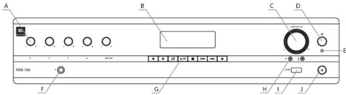
Figure 1.2.1 Front Panel, 1 Channel Model
A. Input Level Controls
B. Media Player Display
C. Output Volume Control(s) Including an Illuminated ring around the output volume control will light green with signal presence while red indicates clipping, i.e. the signal has reached the threshold of audible distortion
D. Power Switch
E. Power on LED illuminates blue when power is switched on.
F. Input 1 - Front panel audio input capability via 1/4" TRS connector. The two channel model includes a second, similar input (Input 4).
G. Media Player Controls
H. Tone Controls - Bass and Treble potentiometers for each output channel.
I. USB Audio Input
J. Bluetooth Key and Indicator
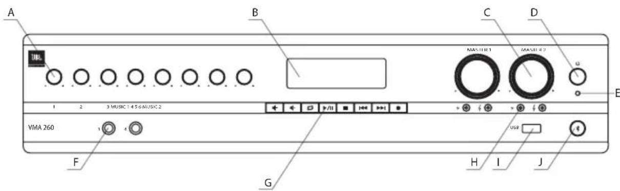
Figure 1.2.2 Front Panel, 2 Channel Model
1.3 Rear Panel Controls & Connectors (VMA160, VMA1120, VMA1240)
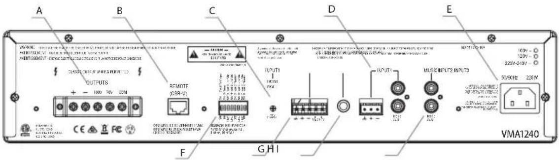
Figure 1.3.1 Rear Panel - VMA 1240
A. Amplifier output connectors.
B. Remote volume connectors – RJ-45 style connector to connect to JBL CSR-V control module.
C. VOX sensitivity adjustment for Input 1.
D. Input 4 may use either Euroblock or RCA style connector.
E. AC Power Inlet – Detachable IEC.
F. Configuration switches control mic/line gain settings and phantom power for the inputs as well as enable the chime and 70V/100V output mode.
G. Input 2 – Euroblock connector provides for audio input and priority contacts that will duck other channels during an announcement when contacts closed using a switch.
H. Input 3 accepts a 1/4" TRS connector.
I. Music input uses a Dual RCA Connector. Stereo, unbalanced sources will be summed together.
1.4 Rear Panel Controls & Connectors (VMA260 & VMA2120)
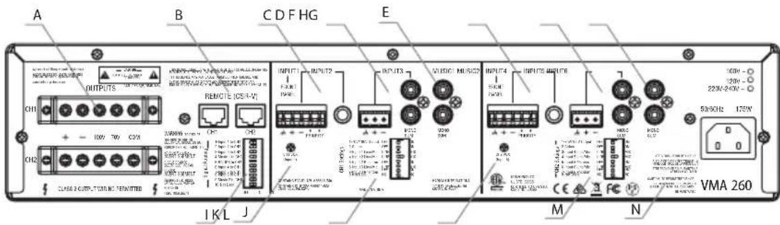
Figure 1.4.1 Rear Panel - VMA 260
A. Amplifier output connectors.
B. Remote volume connectors – RJ-45 style connector to connect to JBL CSR-V control modules.
C. Input 2 – Input audio through either the Euroblock connector or the 1/4" TRS connector. Pins 4 and 5 of the Euroblock are priority contacts that will duck other channels during an announcement when the contacts are closed using a switch.
D. Input 3 accepts input through either the 3-pin Euroblock or the Dual RCA jacks. Stereo, unbalanced sources will be summed into a mono signal.
E. Music1 input uses a Dual RCA Connector. Stereo, unbalanced sources will be summed together.
F. Input 5 – Input audio through either the Euroblock connector or the 1/4" TRS connector. Pins 4 and 5 of the Euroblock are priority contacts that will duck other channels during an announcement when the contacts are closed using a switch.
G. Input 6 accepts input through either the 3-pin Euroblock or the Dual RCA jacks. Stereo, unbalanced sources will be summed together.
H. Music2 input uses a Dual RCA Connector. Stereo, unbalanced sources will be summed together.
I. Signal Routing DIP switch is used to route inputs to both output channels. By default, each group of inputs is routed only to its respective output channel (Input 1 – Music1 are routed to output CH1, Input 4 – Music2 are routed to output CH2).
J. VOX sensitivity adjustment for Input 1.
K. CH1 Settings DIP switch is used to enable the 70V/100V output option, turn on the chime feature, select input gain, and enable phantom power for CH1.
L. VOX sensitivity adjustment for Input 4.
M. CH2 Settings DIP switch is used to enable the 70V/100V output option, turn on the chime feature, select input gain, and enable phantom power for CH2.
N. AC Power Inlet – Detachable IEC.
2.0 Setup
2.1 Unpacking Your Amplifier
Please unpack and inspect your amplifier for any damage that may have occurred during transit. If damage is found, notify the transportation company immediately. Only you can initiate a claim for shipping damage. We will be happy to help as needed. Save the shipping carton as evidence of damage for the shipper's inspection.
We also recommend that you save all packing materials so you will have them if you ever need to transport the unit. Never ship the unit without the factory pack.
WARNING: Before you start to set up your amplifier, make sure you read and observe the Important Safety Instructions found at the beginning of this manual.
2.2 Installing Your Amplifier
CAUTION: Before you begin, make sure your amplifier is disconnected from the power source and all level controls turned completely down (counterclockwise).
Note: We recommend that any sensitive equipment be located at least 8 inches (20 cm) away from the amplifier.
To install the amplifier, you can use one of the following approaches:
- Rack mount the amplifier with the rack mounting kit, see Figure 2.2.2.
- Place a single amplifier on a surface with 12 inches of air space around the unit for convection cooling. Rubber feet are included and can be attached onto the underside of the chassis. For amplifier dimensions, see Figure 2.2.1.
FRONT VIEW
![88.10 mm [3.47 in] MASTER 2 MASTER 1 122 MUSIC 1 456 MUSIC 2 VMA 260 432.00 mm [17.00 in]](/content/2026/05/812985/images/f164638bc6b9836de36897926e904d8a4903d7132e398a281fa0701ccaa4515b.jpg)
SIDE VIEW
![401.00 mm [15.79 in]](/content/2026/05/812985/images/681161aa092343768288297bf1caa9c3a887b32ef635386328bd831d0e1f7b5a.jpg)
Figure 2.2.1 Dimensions
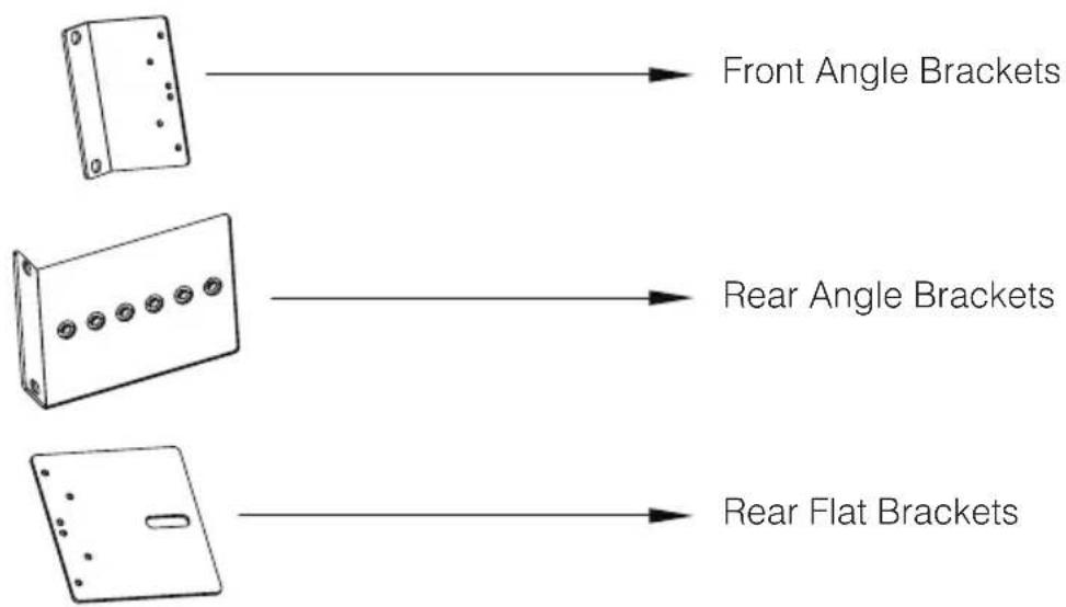
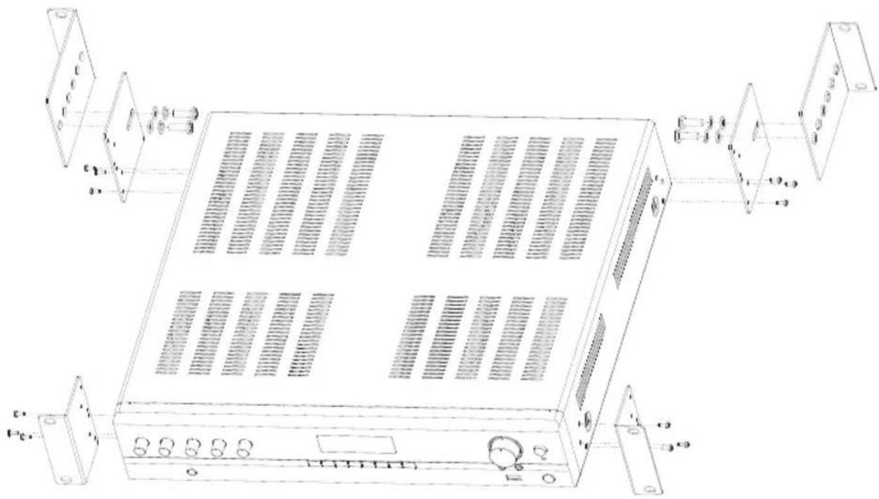
Figure 2.2.2 Mounting Kit
natural_image
Technical line drawing of a server rack with ventilation grilles and control panel (no text or symbols)Figure 2.2.3 Rack Mounting the Mixer-Amplifier
To install, refer to Figure 2.2.3 and follow the steps below:
-
Attach the front angle brackets to each side of the front of the amplifier using the screws provided.
-
Attach the rear flat brackets to each side of the rear of the amplifier with the screws provided.
-
Install the unit into the cabinet using the rack mount screws through the front angle brackets. For details of installation in the chassis of the cabinet, refer to the user guide of your cabinet.
-
Align the rear angle brackets with the proper holes at the rear of the cabinet and attach using rack mount screws.
-
With the rear angle brackets to the outside of the flat brackets, attach them each using a screw passing through two washers, the rear flat bracket and the rear angle bracket as shown in the figure.
2.3 Ensuring Proper Cooling
When using an equipment rack, keep a minimum space of 4 inches (10 cm) from the top surface of the unit. Close any open spaces in the rack with blank panels. DO NOT block any air vents. The side walls of the rack should be a minimum of 2 inches (5 cm) from the amplifier sides. The back of the rack should be open.
2.4 Choosing Input Wire & Connectors
We recommend using pre-built or professionally wired balanced line (two-conductor plus shield) 22-24 gauge cables to connect the amplifier balanced input by using the included Euroblock connectors, see Figure 2.4.1. Unbalanced lines may be used, but may result in hum or RF noise if using very long cable runs.
You can also use RCA connectors to connect audio devices, for example, CD/DVD player. However, do not use both Euroblock and RCA audio input connectors on a single channel at the same time.
NOTE: Custom wiring should only be performed by qualified personnel.
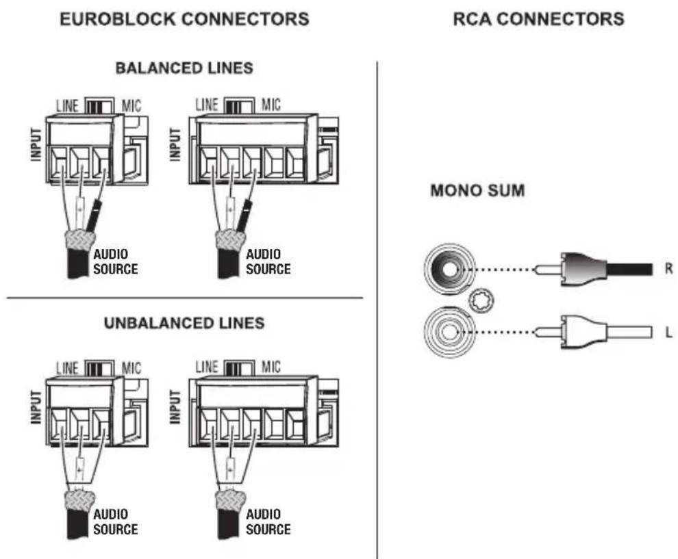
Figure 2.4.1 Input Wiring
NOTE: Two RCA connectors are provided for summing left and right channels from a stereo source. Do not use both Euroblock and RCA connectors concurrently for any single input channel.
2.5 Output Wiring & Connectors
To drive distributed speaker systems designed to operate at 70V or 100V, connect to the corresponding output terminals.
JBL recommends using pre-built or professionally wired, high-quality, two-conductor, heavy gauge speaker wire. Speaker wires should be twisted cable, if possible. To prevent the possibility of short-circuits, the wires should be stripped back no greater than 6 mm (1/4 inch), see Figure 2.5.1.
Suggested below are guidelines to select the appropriate size of wire based on the distance from amplifier to speaker. Check with local code as this may vary.
Distance Wire Size
Up to 25 ft. (7.6m) 16AWG
26-40 ft. (7.9-12.2m) 14AWG
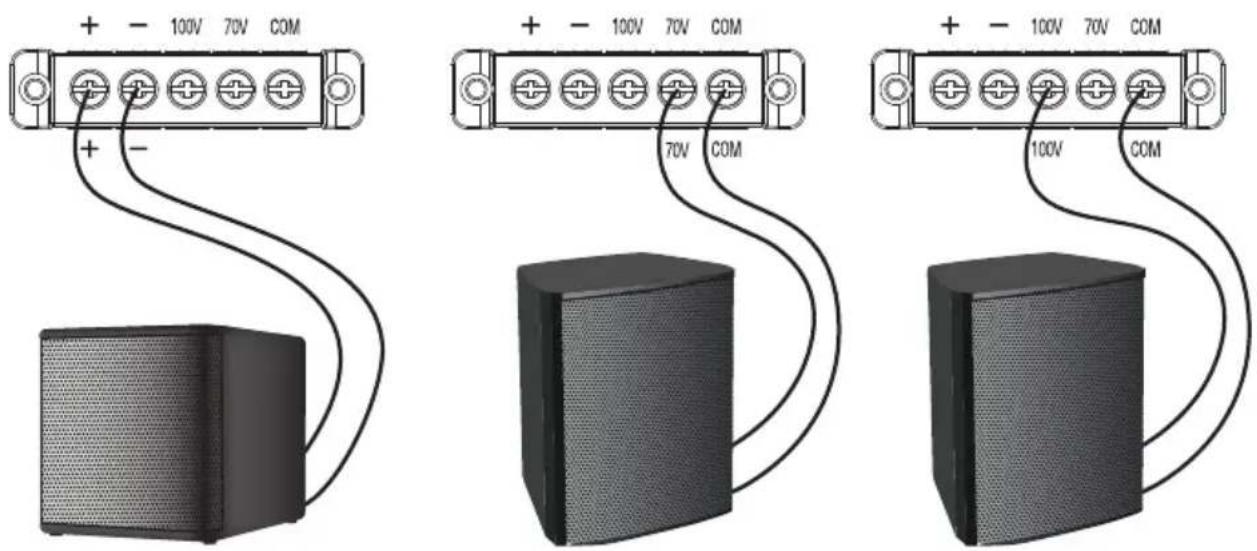
8 Ohm Speaker 100V Speaker System70V Speaker System
Figure 2.5.1 Output Wiring
2.6 Wiring Your Audio System
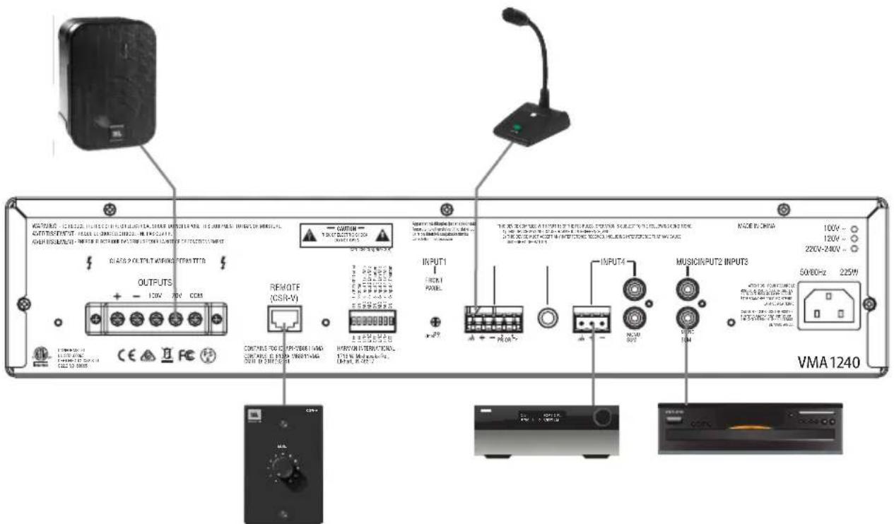
Figure 2.6.1 Wiring Audio System
Typical input and output connections are shown in Figure 2.6.1.
INPUTS: Connect input wiring for both channels using either the RCA or the Euroblock input for each channel.
OUTPUTS: You may use either low impedance or high impedance speakers. Always be sure to maintain the proper polarity when wiring speakers.
Low Impedance Speakers should be driven using the +/- pins of the amplifier output connector. The minimum impedance an amplifier channel can drive is 4 Ohms. Therefore, you can connect up to four 16 Ohm speakers, two 8 Ohm speakers or one 4 Ohm speaker to an amplifier output channel.
High Impedance Speakers should be driven using the appropriate (70V or 100V) pin to speaker (+) and the COM pin to speaker (-) of the amplifier output connector. The minimum impedance that can be driven from each output is provided in Appendix A. Note that the HI-Z switch must be ON in order to provide audio to the high impedance outputs.
WARNING: Do not connect to both low impedance speakers and high impedance speakers from the same audio output channel.
2.7 Connecting to AC Mains
Connect your amplifier to the AC mains power source (power outlet) with the supplied AC power cord. First, connect the IEC end of the cord set to the IEC connector on the amplifier; then, plug the other end of the cord set to the AC mains. When properly connected to a live power source, the power LED should illuminate blue.
WARNING: The third prong of this connector (ground) is an important safety feature. Do not attempt to disable this ground connection by using an adapter or other methods.
Amplifiers don't create energy. The AC mains voltage and current must be sufficient to deliver the power you expect. You must operate your amplifier from an AC mains power source with not more than a 10% variation above or below the specified line voltage and within the specified frequency range indicated on the back panel of the amplifier. If you are unsure of the output voltage of your AC mains, please consult your electrician.
2.8 Protecting Your Speakers
It's wise to avoid clipping the amplifier signal. Not only does clipping sound bad, but it can damage high-frequency drivers. The built-in clip limiter prevents clipping.
Also, avoid sending strong subsonic signals to the amplifier. High-level, low-frequency signals from breath pops or dropped microphones can blow out drivers. You can switch to the HI-Z mode which, in addition to switching in the output transformers for 70V and 100V speakers, activates the high-pass filter. The filter prevents potentially damaging subsonic signals from going to the amplifier by eliminating signals below 70Hz.
2.9 Startup Procedure
Use the following procedure when first turning on your amplifier:
- Turn down the level of your audio source.
- Turn down the level controls of the amplifier.
- Power up the amplifier. The blue Power LED should be ON.
- Turn up the level of your audio source to an optimum level.
- Turn up the Level controls on the amplifier until the desired loudness or power level is achieved.
If you ever need to make any wiring or installation changes, don't forget to disconnect the power cord.
3.0 Operation
3.1 Precautions
Your amplifier is protected from internal and external faults, but you should still take the following precautions for optimum performance and safety:
- Before use, your amplifier first must be configured for proper operation, including input and output wiring hookup. Improper wiring can result in serious operating difficulties.
For information on wiring and configuration, please consult the Setup section of this manual. - Use care when making connections, selecting signal sources and controlling the output level.
- Always be sure to have all levels at minimum when connecting or disconnecting audio sources from the inputs, especially when MIC is selected from the MIC/LINE switch. Failure to do so may cause the amplifier or speaker to go into a protection mode or even cause damage.
- WARNING: Never connect the output to a power supply, battery or power main. Electrical shock may result.
- Tampering with the circuitry, or making unauthorized circuit changes may be hazardous and invalidates all agency listings.
- Do not operate the amplifier with the red Clip LEDs constantly flashing.
- Do not overdrive the mixer, which will cause clipped signal to be sent to the amplifier. Such signals will be reproduced with extreme accuracy, and loudspeaker damage may result.
- Do not operate the amplifier with less than the rated load impedance. Due to the amplifier's output protection, such a configuration may result in premature clipping and speaker damage.
- Use the amplifier in a well-ventilated environment and do not use it in ambient temperature conditions in excess of 40^ C. Failure to do so will result in the automatic disconnection from the power supply as the overheat auto protection function will be activated and there will not be any audio signal coming out of the amplifier. In this case, turn down the volume to the minimum, and the amplifier will soon resume working. When the amplifier returns to normal temperature you may turn the volume up to a safe level.
- If the line voltage to the amplifier is too low, the low voltage protection function will be activated.
CAUTION: JBL is not liable for damage that results from overdriving other system components.
3.2 Input Routing
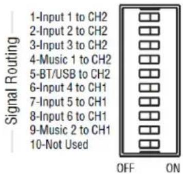
The two-channel models, VMA260 and VMA2120, include a default routing of Input channels 1-3, Music 1 and the Bluetooth/USB source to amplifier 1. Input channels 4-6 and Music 2 are routed to amplifier 2. The user may take any input and have it routed to both outputs by selecting the appropriate switch. For example, if you set switch 1 to ON, Input 1 will be routed to both AMP1 and AMP2.
3.3 Configuration Settings
A DIP switch is available for each output channel to configure the unit to your specific system.
3.3.1 70V/100V Output Selection
When this switch is in the "OFF" position, the amplifier is configured to drive low impedance speakers, (4 Ohms ,minimum) The 70V/100V switch will activate the built-in output transformer allowing the unit to directly drive 70V or 100V speaker systems when connected to the appropriate output terminals. As an added feature when driving the high impedance speakers, the system automatically apply a 70Hz high pass filter.
3.3.2 Chime Function
Turning chime ON will enable a chime sound at the onset of an announcement when priority muting is invoked. (See section 3.5, Priority Muting, on the following page.)
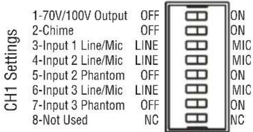
3.3.3 Line/Mic Gain Switch
Additional gain is available for use with sources, in particular microphones, that have low output levels. Switching to MIC position activates 48dB additional gain. Use only when necessary as the added gain may cause higher noise levels.
3.3.4 Phantom Power
Phantom power (27V) can be applied to specific mic inputs by turning on the appropriate Phantom Power switch.
3.4 VOX Function
Voice activated ducking is available on input channel 2 of the VMA160, VMA1120 and VMA1240. The feature is available for both input channels 2 and 5 of the VMA260, and VMA2120. The audio input level required to activate ducking is set using the trim pot on the rear panel. Adjusting in the counterclockwise direction will reduce that level while the full clockwise setting will disable the VOX function.
3.5 Priority Muting
VMA160, VMA1120 and VMA1240 may use Input channel 2 as a priority channel, muting all other channels when pins 4 and 5 are shorted using a switch closure.
The VMA260, and VMA2120 lets Input2 operate with priority over all inputs into output amplifier CH1. Similarly, Input5 can exercise priority over all inputs into output amplifier CH2. Input2 will have priority over both amplifiers CH1 and CH2 if the routing DIP switch #2 is set to ON.
3.6 Remote Volume Control
Remote volume control can be implemented using a CSR-V controller connected via a CAT5 cable to the RJ45 connector on the back panel. For the VMA260 and VMA2120, there are two connectors, one for each amplifier output.
3.7 Media Player
3.7.1 Bluetooth Operation
To activate Bluetooth, perform the following:
- Press the Bluetooth Key until the Bluetooth Indicator begins to flash.
- Enable Bluetooth of your source media player and search for "JBL COMMERCIAL (XX)". Establish a connection. (Note that the "XX" represents the last two digits of the MAC address which allows the user to have multiple systems in close proximity.)
- Once connected, the Bluetooth Indicator will stop flashing and remain illuminated.
- Press the VOLUME UP/VOLUME DOWN keys to increase or decrease the volume.
- Press the NEXT key to jump to the beginning of the next track.
- Press the PREVIOUS key once to jump to the beginning of the current track or twice to the previous track.
- Press the STOP key to stop playing. (Note: This may not work for some Bluetooth devices.)
- Press the PLAY/PAUSE key to pause or resume playing.
- To disconnect, either press the Bluetooth Key or disable Bluetooth at the media player source device. (Note: Play will resume automatically upon reconnect if disconnected by pressing the Bluetooth Key.)
- Press the REC key to start recording. (Note: Media player signals are not recorded.)
Note: Bluetooth signal is muted when broadcasting the chime tone.
3.7.2 USB Operation
- Insert a USB Drive to the USB Audio Input and the number of folders and files on the USB Drive will be displayed.
- Press PREVIOUS or NEXT Key to scroll the playable media.
- Press the VOLUME UP/VOLUME DOWN keys to increase or decrease the volume.
-
Press the REPEAT Key to enter different repeat modes:
-
REPEAT CURRENT – Repeat the current track.
- REPEAT ALL – Repeat all tracks.
-
REPEAT ALL 30Min Message – Play the track with the predefined name, "MESSAGE_1.mp3" every 30 minutes while repeating all other tracks.
-
REPEAT ALL 60Min Message – Play the track with the predefined name, "MESSAGE_1.mp3" every 60 minutes while repeating all other tracks.
-
REPEAT OFF – No repeat.
-
Press the PLAY/PAUSE key to pause or resume playing.
- Press the STOP key to stop playing.
- Press the PREVIOUS Key once to jump to the beginning of the current track or twice to the previous track.
- Hold down the PREVIOUS Key to rewind.
- Press the NEXT Key to jump to the beginning of the next track.
- Hold down the NEXT Key to fast forward.
- Press the REC key to start recording. (Note: Media player signals are not recorded.)
3.7.3 Additional Media Player Information
Bluetooth playback will always have priority over USB.
The default media player volume is maximum.
USB and Bluetooth signals cannot be recorded.
While playing from the USB or Bluetooth source, the signal being played is interrupted momentarily when a chime tone is sounding in another channel.
Hidden functions are available by pressing and holding a media player key for more than 1 second then pressing and holding the Bluetooth key along with it.
- RECORD (>1s) + BT Displays the BT MAC address
- STOP (>1s) + BT Displays the firmware version
- PLAY (>1s) + BT Illuminates all dots in the display
- REPEAT (>1s) + BT Factory Reset
3.7.4 Firmware Upgrade Procedure
- Place the firmware file “*.mcs” onto a blank USB Drive.
- Insert the USB Drive.
- Display will show "USB UPGRADE".
- Wait until display shows "USB SUCCESS" and the display turns off.
- Power off the unit.
- Remove the USB Drive.
- Power on the unit, the upgrade procedure is finished.
4.0 Troubleshooting
CONDITION: No power to the mixer-amplifier so that the power LED is not illuminated.
POSSIBLE REASON: The mixer-amplifier is not plugged into the power outlet.
CONDITION: No sound or low sound.
POSSIBLE REASON: The input signal is not present or at a very low level.
POSSIBLE REASON: The Master Volume control is turned down.
POSSIBLE REASON: A CSR-V is connected and turned down.
POSSIBLE REASON: Mixer channel inputs are turned down.
POSSIBLE REASON: A Priority switch is closed, muting all except the priority input.
POSSIBLE REASON: The 70V/100V switch is OFF while using the 70V or 100V outputs.
CONDITION: Distorted sound.
POSSIBLE REASON: Input signal level is too high. Please turn down the input level controls. Note that the mixer-amplifier should not be operated at a level that allows the clip indicator (red ring around the Master Volume) to be constantly ON.
POSSIBLE REASON: Master Volume is too high.
POSSIBLE REASON: MIC/LINE switch is in MIC position when using a line level source.
Appendix A: Preliminary Performance Specifications
| Performance VMA160 VMA1120 VMA1240 VMA260 VMA2120 | |||||
| Max Output Power per Channel into 4 Ω or 8 Ω; 1kHz, ≤ 0.5% THD | 60W 120W | 240W 60W 120W | |||
| Insertion Loss (70V & 100V outputs) | 1 dB maximum | ||||
| Number of Input Channels | 5 5 5 8 8 | ||||
| Number of Output Channels | 1 1 1 2 2 | ||||
| Tone Controls (Bass and Treble non-detented potentiometers on each channel) | Bass +/-14dB @ 50HzTreble +/-14dB @ 10kHz | ||||
| Input Sensitivity (to obtain full rated power into 8 Ω load) | Mic Input: 5.5mVRMSLine Input: 1.3VRMSRCA Input (stereo in): 130mVRMS | ||||
| Frequency Response (measured at 2.83VRMSinto rated load impedance at any output) | 4/8 Ω Output: 20Hz - 20kHz, +/-2dB70V/100V Outputs: 80Hz - 15kHz +/-3dB | ||||
| Total Harmonic Distortion (THD) (measured at 2.83VRMSinto rated load impedance at any output) | Power Amp Output: <0.5%, 20Hz - 20kHz | ||||
| Signal-to-Noise Ratio (Ref. Rated Power, mixer levels @ min., master volume @ max. A-weighted) | >76dB | ||||
| Input Impedance (nominal) | Mic: 400 ΩLine: 20 kΩ (balanced)RCA: 50 kΩ | ||||
| Phantom Power | 27VDC | ||||
| Crosstalk (reference rated power, volume at mid position, 1kHz) | -70 dB | ||||
| Nominal AC Line Voltages | 100V, 120V, 220V, 220-240V, 50/60 Hz | ||||
| Minimum Load Impedance Low Impedance Output | 4 Ω | 4 Ω | 4 Ω | 4 Ω | 4 Ω |
| 70V Output | 80 Ω | 40 Ω | 20 Ω | 80 Ω | 40 Ω |
| 100V Output | 160 Ω | 80 Ω | 40 Ω | 160 Ω | 80 Ω |
| Operating Temperature/Humidity | 0°C to 35°C @ 95% R.H. (non-condensing) | ||||
| Storage Temperature | -20°C to 85°C | ||||
| Dimensions & Weight | |||||
| Net Weight | 19.4 lb(8.8 kg) | 20.2 lb(9.2 kg) | 25.5 lb(11.6 kg) | 25.5 lb(11.6 kg) | 29.3 lb(13.3 kg) |
| Dimensions | Width: 17.0 in. (432 mm)Depth: 16.3 in. (415 mm)Height: 3.5 in. (88 mm) | ||||
| Shipping Weight | 24.6 lb(11.2 kg) | 25.5 lb(11.6 kg) | 30.8 lb(14 kg) | 30.8 lb(14 kg) | 34.5 lb(15.7 kg) |
Note: For AC power draw and thermal dissipation information, please visit our website. www.jblcommercialproducts.com
Appendix B: Block Diagrams
VMA260 & VMA2120
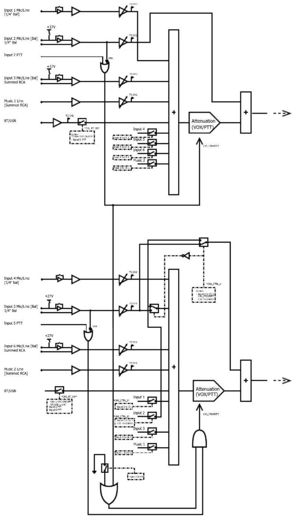
flowchart
Electronic circuit diagram showing signal processing paths for a summed RC system with microlines, PTTs, and attenuators.VMA260 & VMA2120 Continued
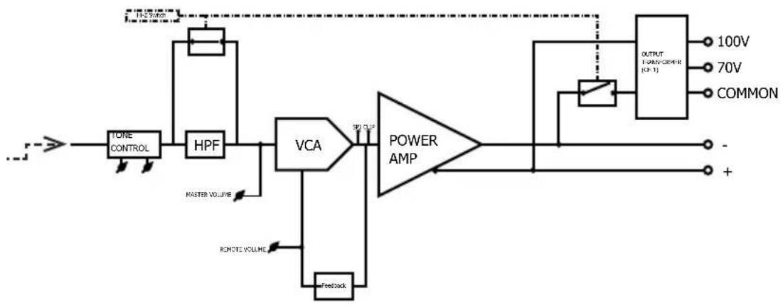
flowchart
graph LR
    A["TOLE CONTROL"] --> B["HPF"]
    B --> C["VCA"]
    C --> D["POWER AMP"]
    D --> E["OUTPUT FANOS/CHINE (C)"]
    E --> F["100V"]
    E --> G["70V"]
    E --> H["COMMON"]
    C --> I["Feedback"]
    I --> J["RMOTE VOLUME"]
    C --> K["MASTER VOLUME"]
    K --> L["Ground"]
    D --> M["SPI OUT"]
    M --> N["Ground"]
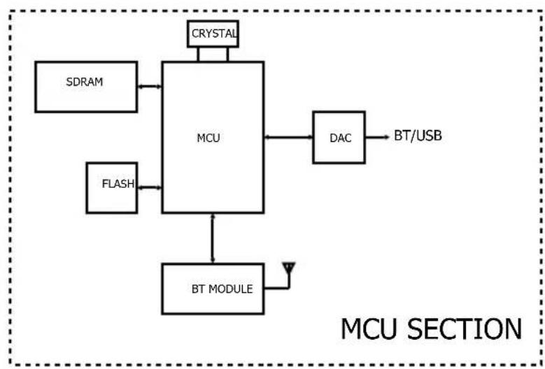
flowchart
graph TD
    A["SDRAM"] --> B["MCU"]
    C["FLASH"] --> B
    D["CRYSTAL"] --> B
    B --> E["DAC"]
    E --> F["BT/USB"]
    B --> G["BT MODULE"]
    G --> H["Antenna"]
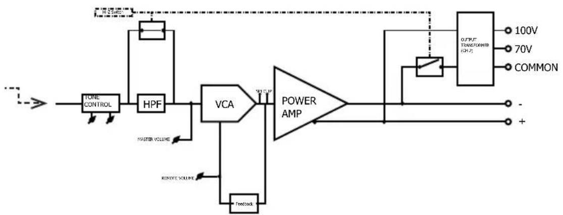
flowchart
graph LR
    A["TORE CONTROL"] --> B["HPF"]
    B --> C["VCA"]
    C --> D["POWER AMP"]
    D --> E["OUTPUT TRANSFER (CHP)"]
    E --> F["100V"]
    E --> G["70V"]
    E --> H["COMMON"]
    C --> I["Feedback"]
    C --> J["MASTER VOLUME"]
    C --> K["REMOTE VOLUME"]
    D --> L["Ground"]
    style A fill:#f9f,stroke:#333
    style E fill:#ccf,stroke:#333
VMA160, VMA1120 & VMA1240
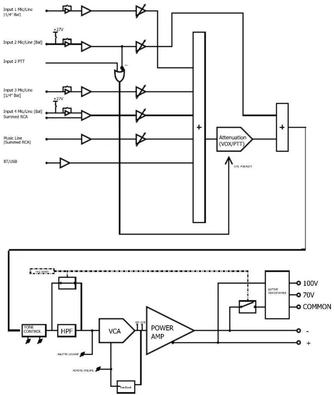
flowchart
graph TD
    A["Input 1 Mic/Line [1/4" Bal"]] --> B["NOT"]
    C["Input 2 Mic/Line [Bal"]] --> D["NOT"]
    E["Input 2 PTT"] --> F["OR"]
    G["Input 3 Mic/Line [1/4" Bal"]] --> H["NOT"]
    I["Input 4 Mic/Line [Bal"] Summed RCA] --> J["NOT"]
    K["Music Line [Summed RCA"]] --> L["NOT"]
    M["BT/USB"] --> N["NOT"]
    B --> O["Attenuation (VOX/PTT)"]
    D --> O
    F --> O
    H --> O
    J --> O
    L --> O
    N --> O
    O --> P["+"]
    P --> Q["Output"]
    Q --> R["OUTPUT TRANSFORMER"]
    R --> S["100V"]
    R --> T["70V"]
    R --> U["COMMON"]
    V["TONE CONTROL"] --> W["HPF"]
    W --> X["VCA"]
    X --> Y["POWER AMP"]
    Y --> Z["-"]
    Y --> AA["+"]
    AB["MASTER VOLUME"] --> AC["Feedback"]
    AD["REMOTE VOLUME"] --> AE["Feedback"]
    AF["CHK PRIORITY"] --> AG["+"]
    AH["+27V"] --> AI["+"]
    AJ["+27V"] --> AK["+"]
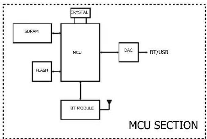
flowchart
graph TD
    A["SDRAM"] --> B["MCU"]
    C["FLASH"] --> B
    D["CRYSTAL"] --> B
    E["BT MODULE"] --> B
    B --> F["DAC"]
    F --> G["BT/USB"]
    style B fill:#f9f,stroke:#333
Appendix C: Contact Information
For additional information, please consult JBL Professional Customer Service, your system installer or retailer.
On The World Wide Web:
www.jblcommercialproducts.com
Professional Contacts, Outside the USA:
Contact the JBL Professional Distributor in your area. A complete list of JBL Professional international distributors is provided at our U.S.A. Website: www.jblpro.com.
JBL
COMMERCIAL
by HARMAN
JBL Commercial
3000 Research Dr.
Richardson, Texas 75082
Part Number: 5078447-B Issue: 07/19

- Commercial Series
- Channel & 2 Channel Mixer-Amplifier Operation Manual
- Contents
- IMPORTANT SAFETY INFORMATION
- WARNING
- SAFETY INSTRUCTIONS
- WARNING FOR YOUR PROTECTION READ THESE INSTRUCTIONS:
- U.K. MAINS PLUG WARNING
- ELECTROMAGNETIC COMPATIBILITY
- USE GROUNDED OUTLET ONLY!
- FEDERAL COMMUNICATION
- COMMISSION INTERFERENCE STATEMENT
- FCC CAUTION
- IMPORTANT NOTE
- CANADA STATEMENT
- THE FINAL END PRODUCT MUST BE LABELLED IN A VISIBLE AREA WITH THE FOLLOWING
- CE
- EU - DECLARATION OF CONFORMITY
- SUPPLIER DECLARATION OF CONFORMITY (SDoC)
- Object of the declaration:
- The object of the declaration described above is in conformity with the relevant standards:
- Welcome
- Features
- Front Panel Controls & Indicators
- Rear Panel Controls & Connectors (VMA160, VMA1120, VMA1240)
- Rear Panel Controls & Connectors (VMA260 & VMA2120)
- Setup
- Unpacking Your Amplifier
- Installing Your Amplifier
- Ensuring Proper Cooling
- Choosing Input Wire & Connectors
- Output Wiring & Connectors
- Distance Wire Size
- Wiring Your Audio System
- Connecting to AC Mains
- Protecting Your Speakers
- Startup Procedure
- Operation
- Precautions
- Input Routing
- Configuration Settings
- 70V/100V Output Selection
- Chime Function
- Line/Mic Gain Switch
- Phantom Power
- VOX Function
- Priority Muting
- Remote Volume Control
- Media Player
- Bluetooth Operation
- USB Operation
- Additional Media Player Information
- Firmware Upgrade Procedure
- Troubleshooting
- CONDITION: No power to the mixer-amplifier so that the power LED is not illuminated.
- CONDITION: No sound or low sound.
- CONDITION: Distorted sound.
- Appendix B: Block Diagrams
- VMA260 & VMA2120 Continued
- Appendix C: Contact Information
- Professional Contacts, Outside the USA:
Brand : JBL
Model : VMA160
Category : Blender