
Storage Adapter RSP3QD160J - Controller INTEL - Free user manual and instructions
Find the device manual for free Storage Adapter RSP3QD160J INTEL in PDF.


| Product Type | RAID Controller |
| Model | RSP3QD160J |
| Brand | Intel |
| Interface | PCI Express 3.0 x8 |
| Supported Drives | SAS (12 Gbps) and SATA (6 Gbps), up to 16 drives |
| RAID Levels | 0, 1, 10, 5, 50, 6, 60 |
| Cache Memory | 1 GB DDR3 |
| Form Factor | Low-profile MD2 (6.6 x 2.7 x 0.7 inches) |
| Weight | 0.3 lb (approx) |
| Power Consumption | 15 W typical |
| Connectors | 2 x SAS SFF-8643 (internal x4) |
| Operating Temperature | 0°C to 55°C (32°F to 131°F) |
| Storage Temperature | -40°C to 70°C (-40°F to 158°F) |
| Supported Operating Systems | Windows Server 2012/2016/2019, Linux (RHEL, SLES, CentOS), VMware ESXi |
| Management Software | Intel RSTe, Intel Storage Management, CLI |
| Safety Precautions | Use anti-static wrist strap; handle by edges |
| Cleaning and Maintenance | Keep free of dust; use compressed air if needed |
| Warranty | 3 years limited |
| Repairability | No user-serviceable parts; contact Intel support |
Frequently Asked Questions - Storage Adapter RSP3QD160J INTEL
User questions about Storage Adapter RSP3QD160J INTEL
0 question about this device. Answer the ones you know or ask your own.
Ask a new question about this device
Download the instructions for your Controller in PDF format for free! Find your manual Storage Adapter RSP3QD160J - INTEL and take your electronic device back in hand. On this page are published all the documents necessary for the use of your device. Storage Adapter RSP3QD160J by INTEL.
USER MANUAL Storage Adapter RSP3QD160J INTEL
Intel® Storage Controllers RMSP3JD160J, RSP3QD160J and RSP3GD016J
Hardware User Guide
A document providing an overview of product features, specification data, and hardware installation instructions
Rev 1.0
July 2017
Intel® Server Products and Solutions
Document Revision History
| Date Published | Revision | Revision Change Description |
| Jul 2017 | 1.0 | Initial release |
Disclaimers
Intel technologies' features and benefits depend on system configuration and may require enabled hardware, software, or service activation. Performance varies depending on system configuration. No computer system can be absolutely secure. Check with your system manufacturer or retailer or learn more at Intel.com.
No license (express or implied, by estoppel or otherwise) to any intellectual property rights is granted by this document.
Intel disclaims all express and implied warranties, including without limitation, the implied warranties of merchantability, fitness for a particular purpose, and non-infringement, as well as any warranty arising from course of performance, course of dealing, or usage in trade.
The products and services described may contain defects or errors known as errata which may cause deviations from published specifications. Current characterized errata are available on request.
You may not use or facilitate the use of this document in connection with any infringement or other legal analysis concerning Intel products described herein. You agree to grant Intel a non-exclusive, royalty-free license to any patent claim thereafter drafted which includes subject matter disclosed herein.
Intel, the Intel logo, are trademarks of Intel Corporation in the U.S. and/or other countries.
*Other names and brands may be claimed as the property of others.
© Intel Corporation 2017. All rights reserved.
Safety Information
Important Safety Instructions
Read all caution and safety statements in this document before performing any of the instructions. See also Intel Server Boards and Server Chassis Safety Information at https://www.intel.com/content/dam/support/us/en/documents/motherboards/server/sb/g23122-004_safetyregulatory.pdf
Heed safety instructions: Before working with your server product, whether you are using this guide or any other resource as a reference, pay close attention to the safety instructions. You must adhere to the assembly instructions in this guide to ensure and maintain compliance with existing product certifications and approvals. Use only the described, regulated components specified in this guide. Use of other products/components will void the UL listing and other regulatory approvals of the product and will most likely result in noncompliance with product regulations in the region(s) in which the product is sold.
System power on/off: The power button DOES NOT turn off the system AC power. To remove all power from the system, you must unplug the AC power cord from the wall outlet. Make sure the AC power cord is unplugged before you open the chassis, add, or remove any components.
Hazardous conditions, devices and cables: Hazardous electrical conditions may be present on power, telephone, and communication cables. Turn off the server and disconnect the power cord, telecommunications systems, networks, and modems attached to the server before opening it. Otherwise, personal injury or equipment damage can result.
Installing or removing jumpers: A jumper is a small plastic-encased conductor that slips over two jumper pins. Some jumpers have a small tab on top that you can grip with your fingertips or with a pair of fine needle nosed pliers. If your jumpers do not have such a tab, take care when using needle-nosed pliers to remove or install a jumper; grip the narrow sides of the jumper with the pliers, never the wide sides. Gripping the wide sides can damage the contacts inside the jumper, causing intermittent problems with the function controlled by that jumper. Take care to grip with, but not squeeze, the pliers or other tool you use to remove a jumper, or you may bend or break the pins on the board.
Electrostatic discharge (ESD) and ESD protection: ESD can damage disk drives, boards, and other parts. We recommend that you perform all procedures in this chapter only at an ESD workstation. If one is not available, provide some ESD protection by wearing an anti-static wrist strap attached to chassis ground, any unpainted metal surface on your server when handling parts.
ESD and handling boards: Always handle boards carefully. They can be extremely sensitive to ESD. Hold boards only by their edges. After removing a board from its protective wrapper or from the server, place the board component side up on a grounded, static-free surface. Use a conductive foam pad if available but not the board wrapper. Do not slide board over any surface.
1. Preface
1.1 About This Document
This document provides an overview of product features, specification data, and hardware installation instructions for the Intel ^® Storage Controllers RMSP3JD160J, RSP3QD160J and RSP3GD016J.
1.2 Document Organization
This document includes the following:
Chapter 1 – Product Overview – Provides a product overview of the features set and support specifications.
Chapter 2 – General Feature Overview – Provides a brief description for the features that are common for the products covered by this guide.
Chapter 3 – Detailed Characteristics – Provides details on the characteristics for each of the products covered by this guide.
Chapter 4 – Connectivity and Drive Support – Provides description of what drives are supported by the products covered by this guide and the way to connect them.
Chapter 5 – Hardware Installation - Provides support for the installation of the product on the Intel systems where they are supported.
Chapter 6 – Safety and Regulatory
Appendix A. Glossary of Terms
Table of Contents
1. Preface......vii
1.1 About This Document ...... vii
1.2 Document Organization......vii
2. Product Overview....2
3. Intel ^® Tri-Mode RAID Module General Features....3
3.1 Overview....3
3.2 Benefits of the SAS Interface 3
3.3 Benefits of the NVM Express (NVMe) Interface 3
3.4 Intel ^® Tri-Mode RAID Module Features....3
3.4.1 SAS Features....3
3.4.2 SATA III Features....4
3.4.3 NVMe Interface Features....4
3.4.4 Usability Features....4
3.4.5 Flexibility Features....4
3.4.6 Safety Characteristics....4
3.5 Intel ^® Tri-Mode RAID Module Feature Set....5
4. Intel® Tri-Mode Storage Modules and Adapters Detailed Characteristics ......6
4.1 Intel® Integrated RAID Storage Module RMSP3JD160J 6
4.1.1 Intel ^® Storage Module RMSP3JD160J Electrical, Thermal and Atmospheric Requirements.
7
4.1.2 Intel ^® Storage Module RMSP3JD160J Power Consumption....7
4.2 Intel ^® Storage Adapter RSP3QD160J....8
4.2.1 Intel® Storage Adapter RSP3QD160J Electrical, Thermal and Atmospheric Requirements.9
4.2.2 Intel ^® Storage Adapter RSP3QD160J Power Consumption....9
4.3 Intel ^® Storage Adapter RSP3GD016J....10
4.3.1 Intel Storage Adapter RSP3GD016J Electrical, Thermal and Atmospheric Requirements. 11
4.3.2 Intel Storage Adapter RSP3GD016J Power Consumption....11
4.4 SAS/SATA Standards and Communication Protocols....11
4.5 Safety Characteristics....12
5. Connectivity and Drive Support.... 13
5.1 Connectivity and Drive Support....13
5.2 Connector Pinout....13
5.3 SAS/SATA Drive Support....14
5.4 Intel ^® 12 Gb/s SAS 3.0 Expander Support....15
5.4.1 SAS Expander Configuration for the Intel ^® RMSP3JD160F Storage Module and the RSP3QD160J Storage Adapter.... 16
5.5 NVMe Drive Support....18
6. Hardware Installation.... 20
6.1 Storage Module RMS3PJD160J Installation 21
6.1.1 Requirements....21
6.1.2 Packing List.... 21
6.1.3 Installation Instructions....21
6.2 Storage Adapters RS3TJD160J and RS3PGD160J Installation 23
6.2.1 Requirements....23
6.2.2 Packing List.... 23
6.2.3 Installation Instructions.... 23
7. Safety and Regulatory (Class A) 26
7.1 Product Safety Compliance 26
7.2 Product EMC Compliance – Class A Compliance.... 26
7.3 Product Environmental Compliance....26
Appendix A. Glossary 28
List of Figures
Figure 1. Intel® RMSP3JD160F Storage Module layout 6
Figure 2. Intel® RMSP3JD160F Storage Module LED description 7
Figure 3. Intel® RSP3QD160J Storage Adapter layout....8
Figure 4. Intel® RSP3GD016J Storage Adapter layout....10
Figure 5. Intel® RMSP3JD160F RAID Module SFF-8643 connector .... 13
Figure 6. Supported Intel® SAS expander options....15
Figure 7. RAID module RMS3PJD160J SAS port domain identification....16
Figure 8. RAID module RMS3PQD160J SAS port domain identification....16
Figure 9. SAS ports for the RES3FV288....17
Figure 10. SAS ports for the RES3TV360....17
Figure 11. Connecting the AXXCBL700HDCV to the backplane....18
Figure 12. Connecting the AXXCBL700HDCV cable to the RAID module....19
Figure 13. Connecting the AXXCBL700HDCV cable to the storage adapter .... 19
Figure 14. Barrel Standoff Placement and Installation 21
Figure 15. Storage Module Placement and Installation....22
Figure 16 Storage Adapter Installation (insert adapter in slot)....23
Figure 17 Storage Adapter Installation (insert riser card)....24
Figure 18 Storage Adapter Installation (adapter installed)....24
List of Tables
Table 1. Intel ^® Tri-Mode RAID module comparative feature set....5
Table 2. SFF-8643 connector pinout....14
(This page is intentionally left blank.)
2. Product Overview
The Intel ^® Storage Controllers RMSP3JD160J, RSP3QD160J and RSP3GD016J are part of the new family of Intel ^® storage controllers. This new family of Tri-Mode RAID controllers allow connecting host systems to SAS drives, SATA drives, or NVMe drives. These controllers are based on the LSI SAS IC technology.
Intel offers a family of Tri-Mode RAID modules that address the needs for internal connectivity solutions as well as low and high port count:
- RMSP3JD160J – Tri-mode Storage Module with 16 internal ports
- RSP3QD160J – Tri-mode Storage Adapter with 16 internal ports
- RSP3GD016J – Tri-mode Storage Adapter with 16 external ports
3. Intel® Tri-Mode RAID Module General Features
3.1 Overview
The Intel ^® Tri-Mode Storage Controllers include a SAS interface and an NVMe interface. Both share the same connectors by multiplexing the data and sideband signals. As compared with the previous generation of Intel RAID modules, the new Tri-Mode family offers increased performance by reducing latency, increasing IOPS, increasing queue depth and increasing cache memory. They also offer NVMe drive support to allow doing hardware RAID using these new technology drives.
3.2 Benefits of the SAS Interface
SAS is a serial, point-to-point, enterprise-level device interface that leverages the proven SCSI protocol set. SAS is a convergence of the advantages of SATA, SCSI, and Fiber Channel and the mainstay of the enterprise and high-end workstation storage markets.
The SAS interface uses the SCSI command set to ensure reliable data transfers while providing the connectivity and flexibility of point-to-point serial data transfers. The serial transmission of SCSI commands eliminates clock-skew challenges. The SAS interface provides improved performance, simplified cabling, smaller connectors, and lower pin count and power requirements when compared to the original parallel SCSI.
SAS controllers leverage a common electrical and physical connection interface that is compatible with Serial ATA (SATA) technology. The SAS protocols and the SATA III protocols use a common thin, 7-wire connector. The SAS/SATA III connector and cable are easier to manipulate, allow connections to smaller devices, and do not inhibit airflow. The point-to-point SATAIII architecture eliminates inherent difficulties created by the legacy ATA master-slave architecture while maintaining compatibility with existing ATA firmware.
3.3 Benefits of the NVM Express (NVMe) Interface
NVMe (non-volatile memory express) is a storage protocol created to accelerate the transfer of data with solid-state drives (SSDs) by utilizing multiple PCIe connections. Benefits are increased bandwidth (up to 8Gb/s per lane), lower latency, increased efficiency, lower CPU utilization with multiple long command queues and lower power.
3.4 Intel® Tri-Mode RAID Module Features
Next is an explanation of the features of the Intel ^® Tri-Mode RAID Modules.
3.4.1 SAS Features
Characteristics of the SAS interface.
• Supports the following:
-
12 Gb/s, 6Gb/s, and 3Gb/s SAS data transfers per PHY.
o SMP communicating topology management information.
o SSP enabling communication with other SAS devices.
o STP enabling communication with SATA devices through an attached expander. -
Provides a serial, point-to-point, enterprise-level storage interface.
- Simplifies cabling between devices.
- Provides a scalable interface that supports up to 240 devices through the use of expanders.
- Supports x2 through x8 wide ports that consist of two (2), four (4), or eight(8) PHYs within a single port.
• Supports narrow ports consisting of a single PHY - Transfers data by using SCSI information units.
3.4.2 SATA III Features
The SAS interface is compatible with SATA and it has the following characteristics.
• Supports the following:
o SATA III data transfers up to 6Gb/s.
o STP data transfers up to 6Gb/s.
- Provides a serial, point-to-point storage interface.
- Simplifies cabling between devices.
- Eliminates the master-slave construction used in parallel ATA.
- Permits addressing of multiple SATA targets through an expander.
3.4.3 NVMe Interface Features
The new NVMe interface has the following characteristics.
• Supports the following:
- Data transfers of 8Gb/s per lane (32 Gb/s when 4 PCIe lanes are being used).
o PCI Bus Power Management Interface Specification, Revision 1.2.
○ Active State Power Management, states, by placing links in a power-saving mode during times of no link activity.
• Supports PCIe Hot Plug.
• Supports error handling.
- Provides high bandwidth per pin with low overhead and low latency.
• Supports lane reversal and polarity inversion.
3.4.4 Usability Features
The Tri-Mode RAID modules have the next usability characteristics.
- Drives spin-up sequencing control.
- Provides one (1) LED signal to indicate link activity for all PHYs through the motherboard for the drive activity LED on the chassis.
• Supports the internal SAS sideband signal SFF-8485 (SGPIO) interface.
Note: LED signals indicate an error condition or drive activity. RAID modules support several blink patterns for these LEDs, depending on the user configuration and storage enclosure. For information about the LED blink patterns, contact the storage enclosure manufacturer.
3.4.5 Flexibility Features
The Tri-Mode RAID modules have the next flexibility characteristics.
- Flash ROM interface, a non-volatile static RAM (NVSRAM) interface.
- Flexible programming interface to tune I/O performance.
- Permit mixed connections to SAS targets or SATA III targets.
- Leverage-compatible connectors for SAS connections and SATA III connections.
- Permit grouping of up to eight (8) PHYs into a single SAS-wide port.
- Permit programming of the World Wide Name.
3.4.6 Safety Characteristics
All the Intel ^® Tri-Mode RAID Modules meet or exceed the requirements of UL flammability rating 94 V0. Each bare board is also marked with the supplier name or trademark, type, and UL flammability rating.
3.5 Intel® Tri-Mode RAID Module Feature Set
The following table describes the feature set of the Intel Tri-Mode RAID modules.
Table 1. Intel® Tri-Mode RAID module comparative feature set
| Feature | RMSP3JD160J | RSP3QD160J | RSP3GD016J |
| I/O Processor | Avago* SAS3516 PCIe* I/O controller (IOC) | Avago* SAS3416 PCIe* I/O controller (IOC) | Avago* SAS3416 PCIe* I/O controller (IOC) |
| JBOD Mode or Pass through Mode (SAS/SATA) | Yes Yes Yes | ||
| Form Factor | Modular Mezzanine | MD2 (PCIe card) | MD2 (PCIe card) |
| Drive Interface Connectors | 4 | 4 | 4 |
| PCIe* Interface | x8 PCI Express* 3.0. PCIe Performance up to 8 GT/s per lane | x8 PCI Express* 3.0. PCIe Performance up to 8 GT/s per lane | x8 PCI Express* 3.0. PCIe Performance up to 8 GT/s per lane |
| Data Transfer Rates | 12, 6, & 3 Gbps per port SAS, 6 & 3 Gbps per port SATA and 8 Gbps per lane NVMe | 12, 6, & 3 Gbps per port SAS, 6 & 3 Gbps per port SATA and 8 Gbps per lane NVMe | 12, 6, & 3 Gbps per port SAS, 6 & 3 Gbps per port SATA |
| Operating Temperature | Maximum ambient: 55°C | Maximum ambient: 55°C | Maximum ambient: 55°C |
| Operating System | Microsoft Window*, Linux* (SuSE*, Red Hat*) Solaris* FreeBSD* | Microsoft Window*, Linux* (SuSE*, Red Hat*) Solaris* FreeBSD* | Microsoft Window*, Linux* (SuSE*, Red Hat*) Solaris* FreeBSD* |
| Drive Types | SAS, SATA, NVMe | SAS, SATA, NVMe | SAS, SATA |
| Maximum direct attached NVMe Drives supported ** | 4 4 0 | ||
| Maximum SAS/SATA Drives supported (through expanders) *** | 512 512 512 | ||
| Maximin enclosures** | 10 | 10 | 10 |
| MTBF(hours) | 4,697,041 | 6,035,003 | 5,521,811 |
| Standard Warranty | 3 years, AWR options | 3 years, AWR options | 3 years, AWR options |
** This setting is firmware-dependent.
*** Devices include drives and expanders. Drives on dual-ported backplanes count twice.
4. Intel® Tri-Mode Storage Modules and Adapters Detailed Characteristics
4.1 Intel® Integrated RAID Storage Module RMSP3JD160J
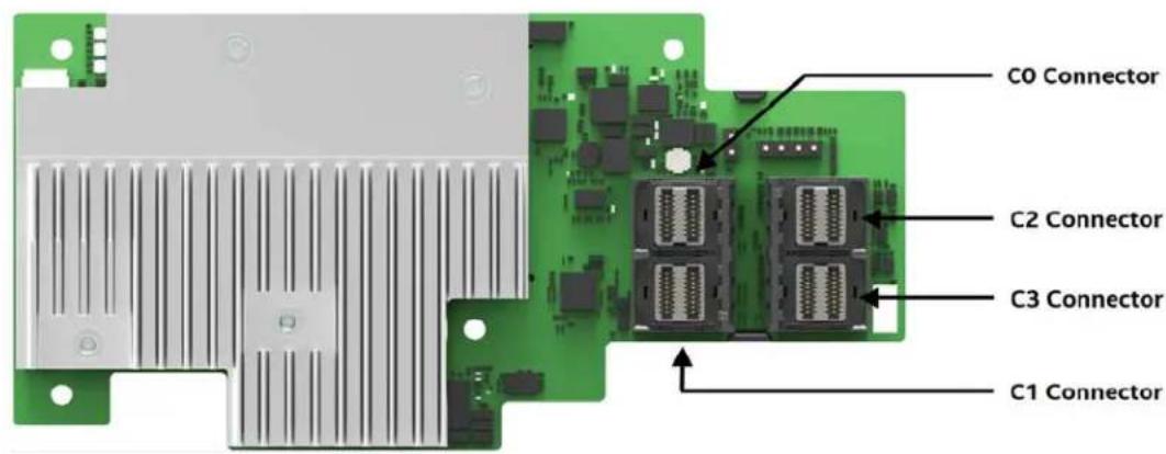
The Intel ^® Storage Module RMSP3JD160J is an entry level tri-mode Storage controller with 16 internal ports based on the Avago ^® SAS3516 RAID-On-Chip (ROC). It has an x8 PCI Express* 3.0. PCIe interface and it supports up to 256 physical SAS/SATA devices** and up to 4 NVMe direct attach NVMe drives. The next figures show the connectors for this module as well as the LED function and placement.
** Physical devices include expanders and if dual-ported back planes are being used, each drive counts twice.
Top side
Bottom side
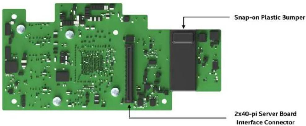
Figure 1. Intel® RMSP3JD160F Storage Module layout
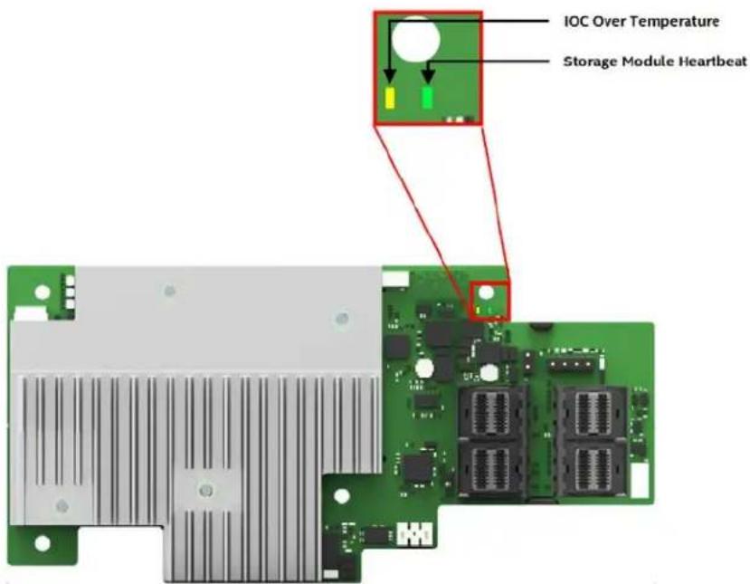
Figure 2. Intel® RMSP3JD160F Storage Module LED description
4.1.1 Intel® Storage Module RMSP3JD160J Electrical, Thermal and Atmospheric Requirements.
List of operating conditions for the 2.1 Intel® Integrated Storage Module RMSP3JD160J:
• Power Supply voltage at the 12V rail (from PCI edge connector): 12V ± 8 percent.
• Power Supply voltage at the 3.3V rail (from PCI edge connector): 13.3V ± 9 percent.
• Relative humidity range is 20 percent to 80 percent non-condensing
• Temperature range: 10 °C to +55 °C (with or without the RMFBU module attached)
List of non-operating conditions (while in storage or in transit) for the Intel® Integrated Storage Module RMSP3JD160J:
• Relative humidity range is 5 percent to 90 percent non-condensing.
• Temperature range: -40^ to +70^ without battery backup unit
• Temperature range: 0°C to +45°C with battery backup unit
4.1.2 Intel ^® Storage Module RMSP3JD160J Power Consumption.
The following table describes the power consumption of the Intel® Storage Module RMSP3JD160J under typical and worst case scenarios:
| Power Rail | Typical | Maximum |
| 3.3V | 1.33W | 1.33W |
| + 12 | 9.21W 9.82W | |
| 3.3V Auxiliary | 0.03W 0.03W | |
| Total Power | 10.57W | 11.18W |
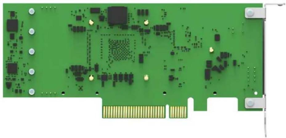
4.2 Intel ^® Storage Adapter RSP3QD160J
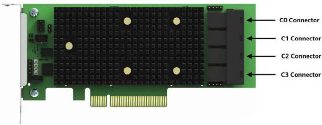
The Intel® Integrated Storage Adapter RSP3QD160J is an entry level tri-mode Storage controller with 16 internal ports based on the Avago® SAS3416 RAID-On-Chip (ROC). It has an x8 PCI Express* 3.0. PCIe interface and it supports up to 512 physical devices**. The next figure describes the connectors for this controller.
** Physical devices include expanders and if dual-ported back planes are being used, each drive counts twice.
Top side
Bottom side
natural_image
Green printed circuit board with various electronic components and connectors (no visible text or symbols)Figure 3. Intel® RSP3QD160J Storage Adapter layout
4.2.1 Intel® Storage Adapter RSP3QD160J Electrical, Thermal and Atmospheric Requirements.
List of operating conditions for the Intel ^® Storage Adapter RSP3QD160J:
• Power Supply voltage at the 12V rail (from PCI edge connector): 12V ± 8 percent.
• Power Supply voltage at the 3.3V rail (from PCI edge connector): 13.3V ± 9 percent.
• Relative humidity range is 20 percent to 80 percent non-condensing
• Temperature range: 10 °C to +55 °C (with or without the RMFBU module attached)
List of non-operating conditions (while in storage or in transit) for the Intel® Storage Adapter RSP3QD160J:
• Relative humidity range is 5 percent to 90 percent non-condensing.
• Temperature range: -40^ to +70^ without battery backup unit
• Temperature range: 0°C to +45°C with battery backup unit
4.2.2 Intel® Storage Adapter RSP3QD160J Power Consumption.
The following table describes the power consumption of the Intel® Storage Adapter RMSP3QD160J under the following states:
State 1: While sitting idle at the DOS prompt or the EFI shell.
State 2: During a drive stress test; average over 20 minutes of sustained operation
| Power rail | State 1 | State 2 |
| 3.3V Supply | 1.6W | 1.6W |
| + 12 Supply | 9.96W | 10.32W |
| 3.3V Auxiliary Supply | 0.03W | 0.03W |
| Total Power | 11.59W | 11.95W |
4.3 Intel® Storage Adapter RSP3GD016J
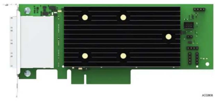
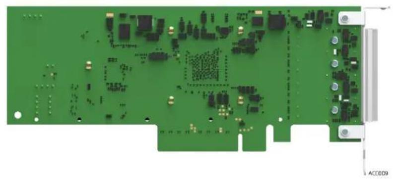
The Intel® Storage Adapter RSP3GD016J is an entry level tri-mode Storage controller with 16 internal ports based on the Avago® SAS3416 RAID-On-Chip (ROC). It has an x8 PCI Express* 3.0. PCIe interface and it supports up to 512 physical devices**. The next figure describes the connectors for this controller. ** Physical devices include expanders and if dual-ported back planes are being used, each drive counts twice.
Top side
natural_image
Green PCI card with black heat sink and gold contacts, no visible text or symbolsBottom side
natural_image
Green printed circuit board with various electronic components and connectors (no visible text or symbols)Figure 4. Intel® RSP3GD016J Storage Adapter layout
4.3.1 Intel Storage Adapter RSP3GD016J Electrical, Thermal and Atmospheric Requirements.
List of operating conditions for the Intel® Storage Adapter RMSP3HD080E:
• Power Supply voltage at the 12V rail (from PCI edge connector): 12V ± 8 percent.
• Power Supply voltage at the 3.3V rail (from PCI edge connector): 13.3V ± 9 percent.
• Relative humidity range is 20 percent to 80 percent non-condensing
• Temperature range: 10 °C to +55 °C (with or without the RMFBU module attached)
List of non-operating conditions (while in storage or in transit) for the Intel® RAID controller RMSP3HD080E:
- Relative humidity range is 5 percent to 90 percent non-condensing.
• Temperature range: -40^ to +70^ without battery backup unit
4.3.2 Intel Storage Adapter RSP3GD016J Power Consumption.
The following table describes the power consumption of the Intel ^® Storage Adapter RSP3GD016J under the following states:
State 1: While sitting idle at the DOS prompt or the EFI shell.
State 2: During a drive stress test; average over 20 minutes of sustained operation
| Power rail | State 1 | State 2 |
| 3.3V Supply | 1.33W | 1.33W |
| +12 Supply | 9.21W | 9.82W |
| 3.3V Auxiliary Supply | 0.03W | 0.03W |
| Total Power | 10.57W | 11.18W |
4.4 SAS/SATA Standards and Communication Protocols
The Intel ^® Tri-Mode RAID controllers support the ANSI Serial Attached SCSI standard, version 3.0. In addition, the controller supports the SATA III protocol defined by the Serial ATA specification, version 3.0. Supporting both the SAS interface and the SATA interface, the SAS controller is a versatile controller that provides the backbone of both server and high-end workstation environments.
Each port on your RAID controller supports SAS devices, SATA devices, or both, by using the following protocols:
• SAS Serial SCSI Protocol (SSP), which enables communication with other SAS devices
• SATA, which enables communication with other SATA devices
- Serial Management Protocol (SMP), which communicates topology management information directly with an attached SAS expander device
- Serial Tunneling Protocol (STP), which enables communication with SATA devices through an attached expander
SAS technology brings a wealth of options and flexibility with the use of SAS devices and SATA devices within the same storage infrastructure. However, SAS devices and SATA devices bring individual characteristics that make each one a more suitable choice depending on the requirements of the given operating environment and storage needs. The Intel® RMS3AC160 RAID Module provides the flexibility to combine these two storage technologies on the same controller and within the same enclosure. However combining SAS drives and SATA drives with the same virtual drive is not supported.
4.5 Safety Characteristics
All the Intel ^® Tri-Mode RAID Controllers meet or exceed the requirements of UL flammability rating 94 V0. Each bare board is also marked with the supplier name or trademark, type, and UL flammability rating.
5. Connectivity and Drive Support
5.1 Connectivity and Drive Support
The Intel ^® Tri- Mode RAID Modules have standard female SFF-8643 (Mini-SAS High-Density) connectors to connect the drives and are designed for the Intel ^® Server Boards and Systems for the next-generation Intel ^® Xeon ^® processor product family. Those systems have the appropriate backplane capable of supporting SAS, SATA and NVMe drives.
5.2 Connector Pinout
The Intel ^® Tri- Mode Storage Modules and Adapters have standard female SFF-8643 (Mini-SAS High-Density) connectors to connect to drives. The connector pinout follows the SFF-9402 specification. SFF-9402 defines how to share sideband signals between SAS and PCI Express (NVMe).
When SAS/SATA drives are connected either as a direct attach through an SFF-8680 bay or through an enclosure, existing 12Gb/s SAS cables and mid-plane connector designs are supported by the RAID module. The next figure shows the pinout for the female SFF-8643 connectors on the module cards.
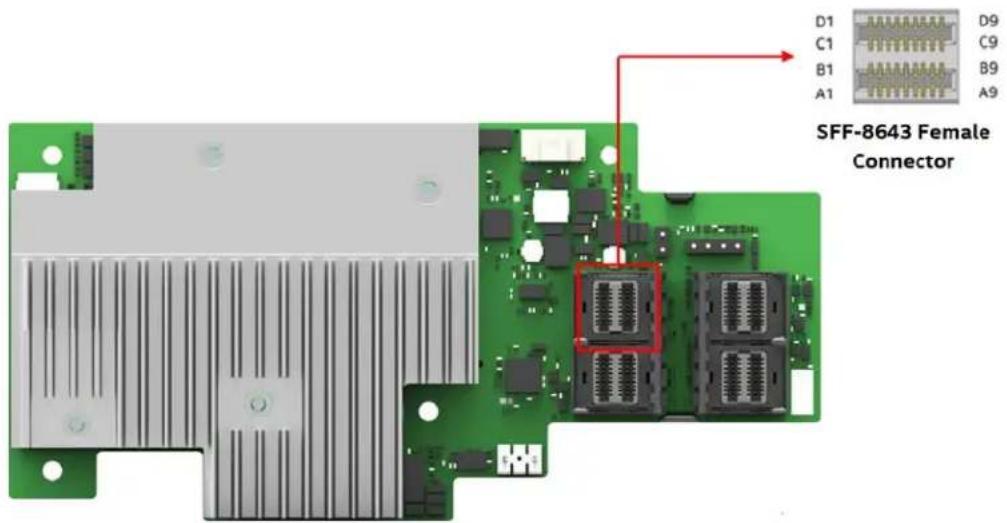
Figure 5. Intel® RMSP3JD160F RAID Module SFF-8643 connector
Table 2. SFF-8643 connector pinout
| Pin# | Signal Name | Pin# | Signal Name | Pin# | Signal Name | Pin# | Signal Name |
| A1 | SB7 | B1 | SB3 GND | C1 | SB4 | D1 | SB5 |
| A2 | SB0 | B2 | SB1 | C2 | SB2 | D2 | SB6 |
| A3 | GND | B3 | GND | C3 | GND | D3 | GND |
| A4 | RX1+ | B4 | RX0+ | C4 | TX1+ | D4 | TX0+ |
| A5 | RX1- | B5 | RX0- | C5 | TX1- | D5 | TX0- |
| A6 | GND | B6 | GND | C6 | GND | D6 | GND |
| A7 | RX3+ | B7 | RX2+ | C7 | TX3+ | D7 | TX2+ |
| A8 | RX3- | B8 | RX2- | C8 | TX3- | D8 | TX2- |
| A9 | GND | B9 | GND | C9 | GND | D9 | GND |
Signals on Pins A1, A2, B1, B2, C1, C2, D1 and D2 are the shared sideband signals.
5.3 SAS/SATA Drive Support
The Intel ^® Tri-Mode RAID Modules are designed to support SAS, SATA and NVMe drives; however, if desired, they can be used to connect only SAS and SATA drives. In this case, standard SAS cables and backplanes can be used (make sure to use only those backplanes which have been tested and listed as compatible hardware).
The Intel® Tri-Mode RAID Modules support the ANSI Serial Attached SCSI standard, version 3.0. In addition, the modules support the SATA III protocol defined by the Serial ATA specification (SAS), version 3.0. Supporting both the SAS interface and the SATA interface, the SAS module is a versatile module that provides the backbone of both server and high-end workstation environments.
Each port on the RAID Module supports SAS devices, SATA devices, or both, through these protocols:
• SAS Serial SCSI Protocol (SSP), which enables communication with other SAS devices
• SATA, which enables communication with other SATA devices
- Serial Management Protocol (SMP), which communicates topology management information directly with an attached SAS expander device, and
- Serial Tunneling Protocol (STP), which enables communication with SATA devices through an attached expander.
SAS technology brings a wealth of options and flexibility with the use of SAS devices and SATA devices within the same storage infrastructure. However, SAS devices and SATA devices bring individual characteristics that make each one a more suitable choice depending on the requirements of the given operating environment and storage needs. The Intel® Tri-Mode modules provides the flexibility to combine these two (2) storage technologies on the same module and within the same enclosure.
Note: combining SAS drives and SATA drives within the same virtual drive is allowed on some modules but Intel discourages this practice.
5.4 Intel® 12 Gb/s SAS 3.0 Expander Support
For system configurations that require more physical SAS/SATA drives then the module's number of ports, the Intel® Tri-Mode RAID Modules can support the following Intel® RAID Expanders:
| Intel Product Code Product Description | |
iPC - RES3FV288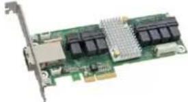 Intel® SAS Expander RES3FV288 Intel® SAS Expander RES3FV288 | SAS 3.0 12 Gb/s expanderFeaturing 6Gbps data aggregation for 12Gbps data transfer with 6Gb/s devicesLow Profile MD2 PCIe* add-in card form factor28 internal ports and 8 external portsPower from PCIe x1HD Mini-SAS 8643 ConnectorsKit includes: (1) SAS Expander card, (2) HD-HD 250mm Expander-to-RAID card cables, and PCI brackets for low profile and full height. |
iPC - RES3TV360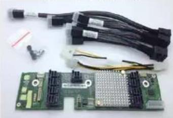 Intel® SAS Expander RES3TV360 Intel® SAS Expander RES3TV360 | SAS 3.0 12 Gb/s expanderFeaturing 6Gbps data aggregation for 12Gbps data transferwith 6Gb/s devicesInternal mount mid-plane form factor36 internal ports supporting point-to-pont 12, 6, and 3 Gb/s data transfer ratesRA 4-pin power connectorHD Mini-SAS 8643 connectorsKit includes: (1) SAS expander card; (1) 130mm power cable; (1 set) Expander-to-backplane cables: (4) HD-HD 165mm, (1) HD-HD 300mm, (1) HD-HD 250mm, (3) Rubber Pads, and mounting screws. |
Figure 6. Supported Intel® SAS expander options
5.4.1 SAS Expander Configuration for the Intel® RMSP3JD160F Storage Module and the RSP3QD160J Storage Adapter
The SAS ports of the Intel® RMSP3JD160F Storage Module and the RSP3QD160J Storage Adapter are driven by two (2) SAS cores and therefore, are divided into two (2) separate SAS domains: Domain 1 and Domain 2. One or two SAS connectors within a common domain can be cabled to a single SAS Expander Card when cabling the RAID Module to a SAS Expander.
Note: Mixing SAS ports from different domains to a single SAS expander card is not supported.
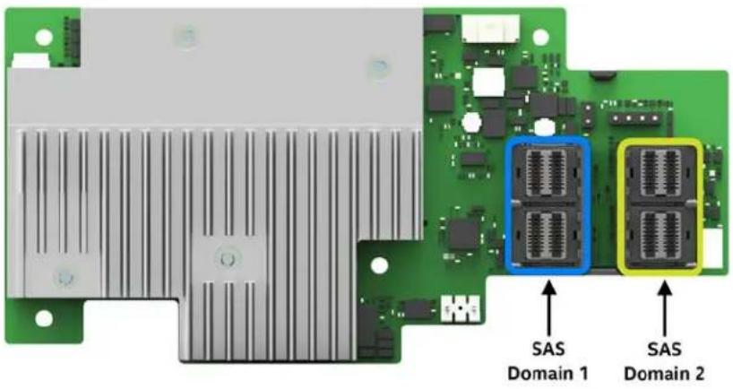
Figure 7. RAID module RMS3PJD160J SAS port domain identification
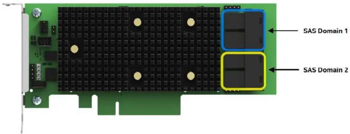
Figure 8. RAID module RMS3PQD160J SAS port domain identification
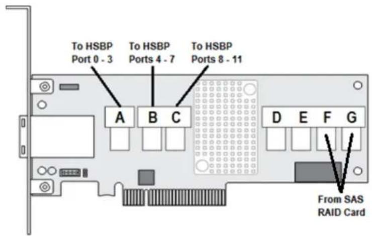
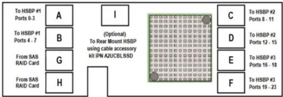
Supported Intel SAS Expanders include several multiport mini-SAS HD (8643) connectors. Some are used as output connectors to a backplane while others are used as input connectors from the RAID Module. The following diagrams identify the connector types for each supported SAS expander card.
flowchart
graph TD
    A["To HSBP #1 Ports 0-3"] --> B["To HSBP #1 Ports 4 - 7"]
    B --> C["From SAS RAID Card"]
    C --> D["From SAS RAID Card"]
    E["To HSBP #2 Ports 8 - 11"] --> F["To HSBP #2 Ports 12 - 15"]
    F --> G["To HSBP #3 Ports 16 - 18"]
    G --> H["To HSBP #3 Ports 19 - 23"]
    I["(Optional) To Rear Mount HSBP using cable accessory kit iPN A2UCBLSSD"] --> J["Green grid pattern"]
    K["I"] --> L["C"]
    K --> M["D"]
    K --> N["E"]
    K --> O["F"]
Input Cable Configuration NOTES:
The SAS Expander cards identified above can support one (1) or two (2) Input SAS port cables.
When routing two (2) input SAS port cables from the RAID Module, use cables from the same SAS domain, as illustrated on the previous page.
Important notice:
Be careful not to connect a SAS expander to a RAID module port configured for NVMe use.
5.5 NVMe Drive Support
The Intel ^® Tri-Mode RAID modules are designed to support SAS, SATA and NVMe drives; however, if desired, they can be used to connect only NVMe drives.
Note1: At launch time no mixed mode is allowed, this means that either SAS/SATA or NVMe drives can be used but not the combination of the two. The mixed mode will be supported at a later firmware version.
The support for NVMe drives is limited to the U.2 (SFF-8639) form factor, connected through a supported backplane using a specially designed Tri-Mode cable. This cable has one (1) dual SF-SFF-8643 (Mini-SAS High-Density) on one end and two (2) OCuLink connectors on the other end to connect to the backplane (the backplane too has both, SF-SFF-8643 and OCuLink connectors). The Intel Part Number for this cable is AXXCBL700HDCV and it connects up to two NVMe drives. Due to limitations on the AXXCBL700HDCV cable, it is only supported on the 2U systems.
Note2: Previous generation servers like the R2000WT family or the S2600CW family provide support for NVME drives using a special NVMe kit which includes a backplane. This backplane only has SFF-8643 (Mini-SAS HD) connectors and is NOT compatible with the Tri-Mode RAID Modules.
Note 3: Using the cable AXXCBL700HDCV on a RAID module other than the Tri-Mode RAID modules can damage your equipment. Only use the cables intended for those modules.
The next figures show how to connect the AXXCBL700HDCV cable.
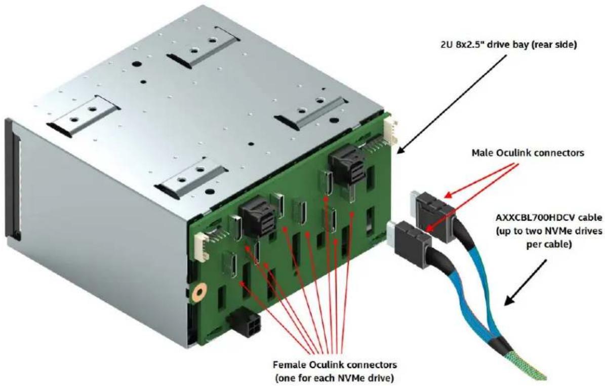
Figure 11. Connecting the AXXCBL700HDCV to the backplane
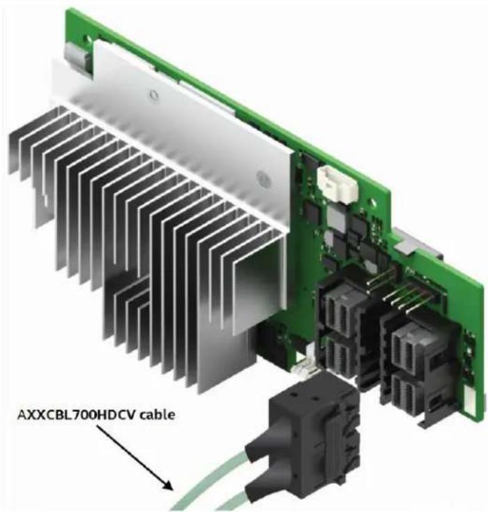
Figure 12. Connecting the AXXCBL700HDCV cable to the RAID module
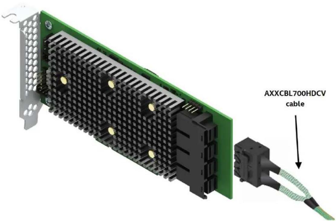
Figure 13. Connecting the AXXCBL700HDCV cable to the storage adapter
6. Hardware Installation
Warnings
Heed safety instructions: Before working with your server product, whether you are using this guide or any other resource as a reference, pay close attention to the safety instructions. You must adhere to the assembly instructions in this guide to ensure and maintain compliance with existing product certifications and approvals. Use only the described, regulated components specified in this guide. Use of other products/components will void the UL listing and other regulatory approvals of the product and will most likely result in noncompliance with product regulations in the region(s) in which the product is sold.
System power on/off: The power button DOES NOT turn off the system AC power. To remove power from the system, you must unplug all AC power cords from the server system before you open the chassis, add, or remove any components.
Hazardous conditions, devices and cables: Hazardous electrical conditions may be present on power, telephone, and communication cables. Turn off the server and disconnect the power cord, telecommunications systems, networks, and modems attached to the server before opening it. Otherwise, personal injury or equipment damage can result.
Installing or removing jumpers: A jumper is a small plastic encased conductor that slips over two jumper pins. Some jumpers have a small tab on top that you can grip with your fingertips or with a pair of fine needle nosed pliers. If your jumpers do not have such a tab, take care when using needle nosed pliers to remove or install a jumper; grip the narrow sides of the jumper with the pliers, never the wide sides. Gripping the wide sides can damage the contacts inside the jumper, causing intermittent problems with the function controlled by that jumper. Take care to grip with, but not squeeze, the pliers or other tool you use to remove a jumper, or you may bend or break the pins on the board.
Electrostatic Discharge (ESD)
Electrostatic discharge can cause damage to your computer or the components within it. ESD can occur without the user feeling a shock while working inside the system chassis or while improperly handling electronic devices like processors, memory or other storage devices, and add-in cards.

Intel recommends the following steps be taken when performing any procedures described within this document or while performing service to any computer system.
- Where available, all system integration and/or service should be performed at a properly equipped ESD workstation
• Wear ESD protective gear like a grounded antistatic wrist strap, sole grounders, and/or conductive shoes - Wear an anti-static smock or gown to cover any clothing that may generate an electrostatic charge
- Remove all jewelry
- Disconnect all cables and cords attached to the server before performing any integration or service
- Touch any unpainted metal surface of the chassis before performing any integration or service
- Hold all circuit boards and other electronic components by their edges only
- After removing electronic devices from the system or from their protective packaging, place them component side up on to a grounded anti-static surface or conductive foam pad. Do not place electronic devices on to the outside of any protective packaging.
6.1 Storage Module RMS3PJD160J Installation
6.1.1 Requirements
The following items are required to install an Intel® RAID Controller:
- Intel® RAID Module
• Intel server board based server system with an empty PCIe slot and a Supported Backplane - Internal Tri-Mode data cables. These cables have one dual SF-SFF-8643 on one end and two oculink connectors on the other end.
• SAS, SATA or NVMe drives
6.1.2 Packing List
1 - Intel Integrated RAID Module w/snap-on bumper (Pre-Installed)
4 – White Plastic Barrel Stand-offs
4 – White Plastic Locking Pins with pull-tab
Note: Intel RAID Products do not include data cables. Appropriate Tri-Mode data cables may be included with your server system or must be purchased separately.
6.1.3 Installation Instructions
-
Unpack the Intel® RAID Module. Unpack and remove your RAID module. Inspect it for damage. If it appears damaged, contact your Intel Customer and Technical Support representative.
-
Turn off the power to the computer, and disconnect the AC power cord.
-
Remove the computer cover. Refer to the system documentation for instructions.
-
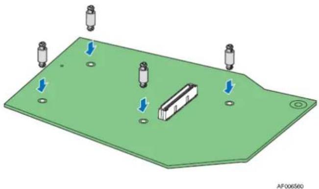
Install the barrel standoffs.
a) Locate the 80-pin SAS module connector on your server board. See your server board documentation.
b) Insert the barrel standoffs into the matching holes in the server board.
natural_image
3D diagram of a green electronic component with four cylindrical pins and a central housing, showing directional arrows (no text or symbols)Figure 14. Barrel Standoff Placement and Installation
- Install the RAID module.
a) Align the module mounting holes over the barrel stand-offs
b) Press down firmly until the module connector is fully engaged with the matching connector on the server board and the module is firmly seated over each barrel standoff.
c) Insert a locking pin into each barrel standoff
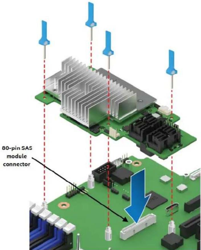
Figure 15. Storage Module Placement and Installation
- Install SAS and / or SATA drives in the host computer case. Refer to the documentation for the devices for any pre-installation configuration requirements.
- Connect internal SAS / SATA data cables to appropriate Drives/Backplane/or Expander card
- Carefully route SAS / SATA data cables back to the Intel RAID Module
- Attach SAS / SATA data cables to the Intel RAID Module
- Reinstall the computer cover, and reconnect the AC power cords to the system
The hardware installation is now complete and the Intel RAID Controller is ready to be configured. For complete Intel RAID module configuration information, refer to the Intel® RAID Software Users Guide available to download from the following Intel Web Site:
http://www.intel.com/supportport
6.2 Storage Adapters RS3TJD160J and RS3PGD160J Installation
6.2.1 Requirements
The following items are required to install an Intel® RAID Adapter:
- Intel® RAID Adapter
• Intel server board based server system with support for an Intel Integrated RAID Adapter
• Internal SAS/SATA data cables
• SAS drives or SATA drives
6.2.2 Packing List
1 – Intel RAID Adapter
2- Low profile mounting bracket
3 - Attention Document
4 – Warranty Document
Note: Intel RAID Products do not include SAS / SATA data cables. Appropriate SAS / SATA data cables may be included with your server system or must be purchased separately.
6.2.3 Installation Instructions
- Unpack the Intel® RAID Adapter.
Unpack your RAID Adapter. Inspect it for damage. If it appears damaged, contact your Intel Customer and Technical Support representative. - Turn off the power to the computer, and disconnect the AC power cord.
- Remove the computer cover. Refer to the system documentation for instructions.
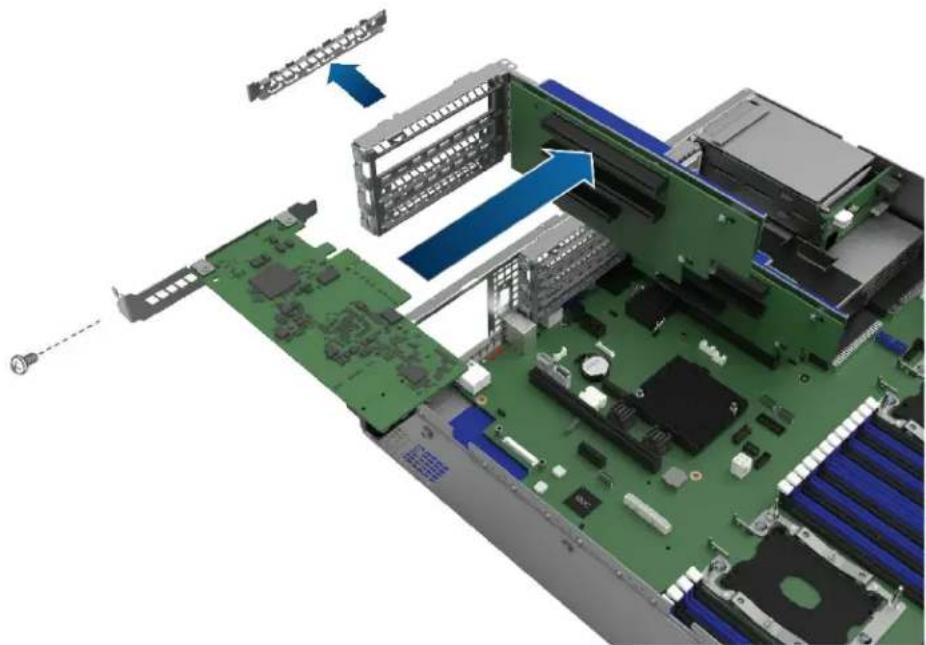
- Install the RAID Adapter.
d) Remove the riser card (the adapter can be installed on any riser card)
e) Remove the filler panel
f) Insert the adapter in the desired slot. Press down gently, but firmly to make sure that the card is seated correctly in the slot. Secure the bracket with the bracket screw.
natural_image
3D rendering of an internal computer motherboard with visible CPU socket, RAM slots, and drive bays (no text or symbols)Figure 16 Storage Adapter Installation (insert adapter in slot)
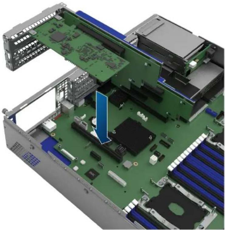
g) Insert back the riser card, press down gently, but firmly.
natural_image
3D cutaway view of a server rack with visible internal components and a blue arrow pointing to a component (no text or symbols)Figure 17 Storage Adapter Installation (insert riser card)
natural_image
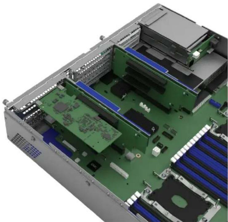
3D cutaway view of a server rack with visible internal components and no text or symbolsFigure 18 Storage Adapter Installation (adapter installed)
- Install SAS and / or SATA drives in the host computer case. Refer to the documentation for the devices for any pre-installation configuration requirements.
- Connect internal SAS / SATA data cables to appropriate Drives or Backplane
- Carefully route SAS / SATA data cables back to the Intel RAID Adapter
- Attach SAS / SATA data cables to the Intel RAID Adapter
- Reinstall the computer cover, and reconnect the AC power cords to the system
The hardware installation is now complete and the Intel RAID Adapter is ready to be configured. For complete Intel RAID Adapter configuration information, refer to the Intel® RAID Software User Guide for full featured and entry level RAID controllers available to download from the Intel Support Site: http://support.intel.com
7. Safety and Regulatory (Class A)
Intel RAID products typically have a variety of individual component level certifications; however final regulatory compliance is based on the combination of the RAID card being integrated within an Intel Server System.
Intended Application – The RAID products are evaluated as Information Technology Equipment (ITE) as part of Intel's server chassis systems. These products are intended to be integrated into Intel server systems that will be installed in offices, schools, computer rooms, and similar commercial type locations. The suitability of this product for other product categories and environments (such as: medical, industrial, telecommunications, NEBS, residential, alarm systems, test equipment, etc.), other than an ITE application, may require further evaluation. Product Safety and EMC Compliance noted below is based on the RAID product integrated into an Intel server.
7.1 Product Safety Compliance
• UL60950 – CSA 60950(USA / Canada)
• EN60950 (Europe)
• IEC60950 (International)
• CB Certificate & Report, IEC60950 (report to include all country national deviations)
• CE - Low Voltage Directive 2006/95/EC (Europe)
7.2 Product EMC Compliance – Class A Compliance
• FCC /ICES-003 - Emissions (USA/Canada) Verification
• CISPR 22 – Emissions (International)
• EN55022 - Emissions (Europe)
• EN55024 - Immunity (Europe)
• CE – EMC Directive 2004/108 EC (Europe)
• VCCI Emissions (Japan)
• AS/NZS 3548 Emissions (Australia / New Zealand)
• BSMI CNS13438 Emissions (Taiwan)
• KC Certification (Korea)
7.3 Product Environmental Compliance
Intel has a system in place to restrict the use of banned substances in accordance with worldwide regulatory requirements. A Material Declaration Data Sheet is available for Intel products. For more reference on material restrictions and compliance you can view Intel's Environmental Product Content Specification at http://supplier.intel.com/ehs/environmental.htm.
• Europe - European Directive 2002/95/EC
o Restriction of Hazardous Substances (RoHS)
Threshold limits and banned substances are noted below.
Quantity limit of 0.1% by mass (1000 PPM) for:
Lead, Mercury, Hexavalent Chromium,
Polybrominated Biphenyls Diphenyl Ethers (PBB/PBDE)
Quantity limit of 0.01% by mass (100 PPM) for:
Cadmium
- California Code of Regulations, Title 22, Division 4.5, Chapter 33: Best Management Practices for Perchlorate Materials
• China – Restriction of Hazardous Substances (China RoHS)
• WEEE Directive (Europe)
• Packaging Directive (Europe) - REACH Directive (Europe)
Appendix A. Glossary
| Term Description | |
| BIOS | Acronym for Basic Input/Output System. Software that provides basic read/write capability. Usually kept as firmware(ROM-based). The system BIOS on the motherboard of a computer boots and controls the system. The BIOS on your host adapter acts as an extension of the system BIOS. |
| configuration | Refers to the way a computer is set up, the combined hardware components (computer, monitor, keyboard, and peripheral devices) that make up a computer system, or the software settings that allow the hardware components to communicate with each other. |
| device driver | A program that permits a microprocessor (through the operating system) to direct the operation of a peripheral device. |
| domain validation | A software procedure in which a host queries a device to determine its ability to communicate at the negotiated data rate. |
| DRAM cache memory | Dynamic random access memory (DRAM) is a type of memory typically used for data or program code that a computer processor needs to function. DRAM is a common type of random access memory (RAM) used in personal computers (PCs), workstations, and servers. |
| drive group | A group of physical drives that combines the storage space on the drives into a single segment of storage space. A hot spare drive does not actively participate in a drive group. |
| EEPROM | Acronym for Electronically Erasable Programmable Read-Only Memory. It is a memory chip that typically stores configuration information, as it provides stable storage for long periods without electricity and can be reprogrammed. See NVRAM. |
| EDLC | Electric Double-Layer Capacitors |
| external SAS device | A SAS device installed outside the computer cabinet. These devices are connected using specific types of shielded cables. |
| Fusion-MPT architecture | Acronym for Fusion-Message Passing Technology architecture. Fusion-MPT consists of several main elements: Fusion-MPT firmware, the Fiber Channel and SCSI hardware, and the operating system-level drivers that support these architectures. Fusion-MPT architecture offers a single binary, operating system driver that supports both Fiber Channel and SCSI devices. |
| host | The computer system in which a RAID controller is installed. It uses the RAID controller to transfer information to and from devices attached to the SCSI bus. |
| host adapter board | A circuit board or circuit that provides a device connection to the computer system. |
| hot spare | An idle, powered on, standby drive that is ready for immediate use in case of drive failure. A hot spare does not contain any user data. A hot spare can be dedicated to a single redundant array or it can be part of the global hot-spare pool for all arrays managed by the controller. When a drive fails, the controller firmware automatically replaces and rebuilds the data from the failed drive to the hot spare. Data can be rebuilt only from virtual drives with redundancy (RAID levels 1, 5, 6, 10, 50, and 60; not RAID level 0), and the hot spare must have sufficient capacity. |
| internal SAS device | A SAS device installed inside the computer cabinet. These devices are connected by using a shielded cable. |
| main memory | The part of computer memory that is directly accessible by the CPU (usually synonymous with RAM). |
| Term Description | |
| NVRAM | Acronym for nonvolatile random access memory. An EEPROM (electronically erasable read-only memory) chip that stores configuration information. See EEPROM. |
| PCI | Acronym for peripheral component interconnect. A high-performance, local bus specification that allows the connection of devices directly to computer memory. The PCI Local Bus allows transparent upgrades from 32-bit data path at 33 MHz to 64-bit data path at 33 MHz, and from 32-bit data path at 66 MHz to 64-bit data path at 66 MHz. |
| PCI Express | Acronym for peripheral component interconnect Express. A high-performance, local bus specification that allows the connection of devices directly to computer memory. PCI Express is a two-way, serial connection that transfers data on two pairs of point- to-point data lines. PCI Express goes beyond the PCI specification in that it is intended as a unifying I/O architecture for various systems: desktops, workstations, mobile, server, communications, and embedded devices. |
| peripheral devices | A piece of hardware (such as a video monitor, drive, printer, or CD-ROM) used with a computer and under the control of the computer. SCSI peripherals are controlled through an Intel® RAID Controller (host adapter). |
| PHY | The interface required to transmit and receive data packets transferred across the serial bus. Each PHY can form one side of the physical link in a connection with a PHY on a different SAS device. The physical link contains four wires that form two differential signal pairs. One differential pair transmits signals, while the other differential pair receives signals. Both differential pairs operate simultaneously and allow concurrent data transmission in both, thereceive and the transmit directions. |
| RAID | Acronym for Redundant Array of Independent Disks (originally Redundant Array of Inexpensive Disks). An array (group) of multiple independent drives managed together to yield higher reliability, performance, or both exceeding that of a single drive. The RAID array appears to the controller as a single storage unit. I/O is expedited because several drives can be accessed simultaneously. Redundant RAID levels (RAID levels 1, 5, 6, 10, 50, and 60) provide data protection. |
| RAID levels | A set of techniques applied to drive groups to deliver higher data availability, performance characteristics, or both to host environments. Each virtual drive must have a RAID level assigned to it. |
| SAS | Acronym for Serial Attached SCSI. A serial, point-to-point, enterprise-level device interface that leverages the proven SCSI protocol set. The SAS interface provides improved performance, simplified cabling, smaller connections, lower pin count, and lower power requirements when compared to parallel SCSI. SAS controllers leverage a common electrical and physical connection interface that is compatible with Serial ATA.The SAS controllers support the ANSI Serial Attached SCSI Standard, Version 2.0. In addition, the controller supports the Serial ATA III (SATA III) protocol defined by the Serial ATA Specification, Version 3.0. Supporting both the SAS interface and the SATA III interface, the SAS controller is a versatile controller that provides the backbone of both server and high-end workstation environments. Each port on the SAS RAID controller supports SAS devices, SATA devices, or both. |
| SAS device | Any device that conforms to the SAS standard and is attached to the SAS bus by a SAS cable. This includes SAS RAID controllers (host adapters) and SAS peripherals. |
| SATA | Acronym for Serial Advanced Technology Attachment. A physical storage interface standard, SATA is a serial link that provides point-to-point connections between devices. The thinner serial cables allow for better airflow within the system and permit smaller chassis designs. |
| SMP | Acronym for Serial Management Protocol. SMP communicates topology management information directly with an attached SAS expander device. Each PHY on the controller can function as an SMP initiator. |
| SSP | Acronym for Serial SCSI Protocol. SSP enables communication with other SAS devices. Each PHY on the SAS controller can function as an SSP initiator. |
| STP | Acronym for Serial Tunneling Protocol. STP enables communication with a SATA device through an attached expander. Each PHY on the SAS controller can function as an STP initiator. |
| stripe | The portion of a stripe that resides on a single drive. |
| stripe size | The total drive space consumed by a stripe not including a parity drive. For example, if a stripe contains 64 KB of drive space and has 16 KB of data residing on each drive, the stripe size is 64 KB and the strip size is 16 KB.A larger stripe size produces improved read performance, especially if most of the reads are sequential. For mostly random reads, select a smaller stripe size. |
| striping | Drive striping writes data across two or more drives. Each stripe spans two or more drives but consumes only a portion of each drive. Each drive, therefore, may have several stripes. The amount of space consumed by a stripe is the same on each drive that is included in the stripe. The portion of a stripe that resides on a single drive is a strip, also known as a stripe element. Striping by itself does not provide data redundancy; striping in combination with parity provides data redundancy. |
| strip size | The drive space consumed by a strip. For example, if a stripe contains 64 KB of drive space and has 16 KB of data residing on each drive, the stripe size is 64 KB and the strip size is 16 KB. The stripe depth is four (four drives in the stripe). You can specify strip sizes of 8 KB, 16 KB, 32 KB, 64 KB, 128 KB, 256 KB, 512 KB, or 1 MB. |
| UPS | Uninterruptible Power Supply. An electrical device that provides power off of a battery when the input power source (AC) fails. |
- Intel® Storage Controllers RMSP3JD160J, RSP3QD160J and RSP3GD016J
- Document Revision History
- Disclaimers
- Safety Information
- Important Safety Instructions
- Preface
- About This Document
- Document Organization
- Table of Contents
- Preface......vii
- Product Overview....2
- Intel ® Tri-Mode RAID Module General Features....3
- Intel® Tri-Mode Storage Modules and Adapters Detailed Characteristics ......6
- Connectivity and Drive Support.... 13
- Hardware Installation.... 20
- Safety and Regulatory (Class A) 26
- Appendix A. Glossary 28
- List of Figures
- List of Tables
- Product Overview
- Intel® Tri-Mode RAID Module General Features
- Overview
- Benefits of the SAS Interface
- Benefits of the NVM Express (NVMe) Interface
- Intel® Tri-Mode RAID Module Features
- SAS Features
- SATA III Features
- NVMe Interface Features
- Usability Features
- Flexibility Features
- Safety Characteristics
- Intel® Tri-Mode RAID Module Feature Set
- Intel® Tri-Mode Storage Modules and Adapters Detailed Characteristics
- Intel® Integrated RAID Storage Module RMSP3JD160J
- Intel® Storage Module RMSP3JD160J Electrical, Thermal and Atmospheric Requirements.
- Intel ® Storage Module RMSP3JD160J Power Consumption.
- Intel ® Storage Adapter RSP3QD160J
- Intel® Storage Adapter RSP3QD160J Electrical, Thermal and Atmospheric Requirements.
- Intel® Storage Adapter RSP3QD160J Power Consumption.
- Intel® Storage Adapter RSP3GD016J
- Intel Storage Adapter RSP3GD016J Electrical, Thermal and Atmospheric Requirements.
- Intel Storage Adapter RSP3GD016J Power Consumption.
- SAS/SATA Standards and Communication Protocols
- Safety Characteristics
- Connectivity and Drive Support
- Connectivity and Drive Support
- Connector Pinout
- SAS/SATA Drive Support
- Intel® 12 Gb/s SAS 3.0 Expander Support
- SAS Expander Configuration for the Intel® RMSP3JD160F Storage Module and the RSP3QD160J Storage Adapter
- Input Cable Configuration NOTES:
- Important notice:
- NVMe Drive Support
- Hardware Installation
- Warnings
- Electrostatic Discharge (ESD)
- Storage Module RMS3PJD160J Installation
- Requirements
- Packing List
- Installation Instructions
- Storage Adapters RS3TJD160J and RS3PGD160J Installation
- Requirements
- Packing List
- Installation Instructions
- Safety and Regulatory (Class A)
- Product Safety Compliance
- Product EMC Compliance – Class A Compliance
- Product Environmental Compliance
Brand : INTEL
Model : Storage Adapter RSP3QD160J
Category : Controller