
SASWT4I - Controller INTEL - Free user manual and instructions
Find the device manual for free SASWT4I INTEL in PDF.


| Product Type | SAS RAID Controller |
| Brand | Intel |
| Model | SASWT4I |
| Form Factor | Low-profile MD2 PCI Express adapter card |
| Dimensions | 6.600 x 2.713 inches (167.64 x 68.91 mm) |
| Weight | Approximately 200 g |
| Power Supply | +3.3V, +12V DC from PCIe slot |
| Power Consumption | 6 W max |
| Host Interface | PCI Express x4 (Rev 1.0A) |
| Data Transfer Rate | 2.5 Gbps per lane |
| SAS Bus Speed | 3 Gbps per port, point-to-point |
| Controller Chip | LSI SAS 1064E |
| Number of Ports | 4 internal ports |
| Supported Drives | SAS and SATA II (up to 14 in IR mode, 122 in IT mode) |
| RAID Levels | 0, 1, 1E, 10E |
| Stripe Size | Fixed 64 KB |
| Cache Options | Disk write cache enable/disable (Write-back or Write-through) |
| Operating Temperature | 0°C to 60°C |
| Humidity | 5% to 90% non-condensing |
| Safety Certification | UL 94 V0, FCC Class B, CE, C-Tick, etc. |
| Enclosure Management | In-band SES with fault LEDs (requires expander backplane) |
| Hot Swap Support | Yes |
| Firmware | 2 MB flash ROM, upgradeable |
| Included Accessories | Standard and low-profile bracket, Resource CD with drivers |
Frequently Asked Questions - SASWT4I INTEL
User questions about SASWT4I INTEL
0 question about this device. Answer the ones you know or ask your own.
Ask a new question about this device
Download the instructions for your Controller in PDF format for free! Find your manual SASWT4I - INTEL and take your electronic device back in hand. On this page are published all the documents necessary for the use of your device. SASWT4I by INTEL.
USER MANUAL SASWT4I INTEL
Intel® RAID Controller SASWT4I Hardware User's Guide
Intel Order Number: E53872-002
DISCLAIMER
INFORMATION IN THIS DOCUMENT IS PROVIDED IN CONNECTION WITH INTEL(R) PRODUCTS. NO LICENSE, EXPRESS OR IMPLIED, BY ESTOPPEL OR OTHERWISE, TO ANY INTELLECTUAL PROPERTY RIGHTS IS GRANTED BY THIS DOCUMENT. EXCEPT AS PROVIDED IN INTEL'S TERMS AND CONDITIONS OF SALE FOR SUCH PRODUCTS, INTEL ASSUMES NO LIABILITY WHATSOEVER, AND INTEL DISCLAIMS ANY EXPRESS OR IMPLIED WARRANTY, RELATING TO SALE AND/OR USE OF INTEL PRODUCTS INCLUDING LIABILITY OR WARRANTIES RELATING TO FITNESS FOR A PARTICULAR PURPOSE, MERCHANTABILITY, OR INFRINGEMENT OF ANY PATENT, COPYRIGHT OR OTHER INTELLECTUAL PROPERTY RIGHT. Intel products are not intended for use in medical, life saving, life sustaining applications.
Intel may make changes to specifications and product descriptions at any time, without notice.
Intel is a trademark or registered trademark of Intel Corporation or its subsidiaries in the United States and other countries.
*Other names and brands may be claimed as the property of others.
Copyright © 2008 by Intel Corporation. Portions Copyright 2005-2008 by LSI Logic Corporation. All rights reserved.
This is the primary reference and user's guide for the Intel ^ RAID Controller SASWT4I, which can be used to manage SAS and SATA II disk drives. It contains installation instructions and specifications.
For details on how to configure the storage adapters, and for an overview of the software drivers, see the Intel ^® IT/IR RAID Software User's Guide on the Resource CD.
Audience
This document assumes that you have some familiarity with storage disk controllers, RAID technology, and related support devices. The people who benefit from this book are:
- Engineers who are designing an Intel ^ RAID Controller SASWT4I for a system.
- Anyone installing an Intel ^ RAID Controller SASWT4I in a RAID system.
Organization
This document includes the following chapters and appendixes:
- Chapter 1 provides a general overview of the Intel ^ RAID Controller SASWT4I.
- Chapter 2 describes the procedures for installing the Intel ^ RAID Controller SASWT4I.
- Chapter 3 provides the characteristics and technical specifications for the Intel® RAID Controller.
- Appendix A lists and explains the terms and abbreviations used in this manual.
Related Publication
The Intel ^® IT/IR RAID Software User's Guide on the Resource CD that is included with the RAID controller.
Table of Contents
Preface ....iii
Audience .... iii
Organization iii
Related Publication ....iii
Chapter 1: Overview ....1
Summary of SAS RAID Controller Features ....1
Usability 2
Redundancy and Error Handling ....2
SAS and SATA Features ....3
Operating System Support ....3
Benefits of Serial-Attached SCSI (SAS) 4
Chapter 2: Intel ^® RAID Controller SASWT4I Hardware Installation ....5
Requirements 5
Installing the RAID Controller 6
Connecting the Cables 9
Configuring the Storage Adapter 9
Replacing a Controller 10
Chapter 3: Intel ^® RAID Controller SASWT4I Characteristics ..... 11
Technical Specifications 12
LEDs 12
Array Performance Features ....13
Fault Tolerance 13
Electrical Characteristics 13
Thermal and Atmospheric Characteristics ....14
Safety Characteristics 14
Appendix A: Glossary of Terms and Abbreviations 15
List of Figures
Figure 1. Inserting the Intel ^® RAID Controller SASWT4I into a PCI Express* Slot ...... 6
Figure 2. Attaching cables to the Intel ^® RAID Controller SASWT4I....7
Figure 3. SAS and SATA Plugs and SAS Backplane Connector....9
Figure 4. Card Layouts.... 11
List of Tables
Table 1. Jumper Descriptions ...... 11
Table 2. Specifications ......12
Table 3. Array Performance Features ......13
Table 4. Fault Tolerance Features ...... 13
Table 5. Electrical Characteristics ...... 13
This chapter provides a general overview of the Intel ^® RAID Controller SASWT4I. It consists of the following sections:
• Summary of SAS RAID Controller Features
• Benefits of Serial-Attached SCSI (SAS)
The Intel ^® RAID Controller SASWT4I is a PCI Express* SAS RAID controller. It provides reliable and fault-tolerant disk subsystem management. This is an ideal RAID solution for the internal storage needs of mid to low-end servers and workstations for use by workgroups and departmental-sized organizations or individuals. The Intel ^® RAID Controller SASWT4I offers a cost-effective way to implement RAID in a server for internal storage.
The SAS controller allows you to use SATA II and SAS hard disk drives in the same system, so you can take advantage of the benefits of each type of drive; however, Intel does not recommend mixing SAS and SATA II drives in the same enclosure.. The controller supports up to 14 physical devices in IR mode and up to 122 devices, including expander devices, in IT (non-RAID) mode. See the ANSI SAS Standard Specification, Version 1.0 for more information about the use of expanders.
As the second generation PCI Express* storage adapter, the Intel ^® RAID Controller SASWT4I addresses the growing demand for increased data throughput and scalability requirements across mid to low-end servers and workstations. Simplified cabling between drives is an additional benefit.
Summary of SAS RAID Controller Features
Note: In this document, the term low-profile refers to the height, not the length, of a PCI add-in card.
The Intel ^® RAID Controller SASWT4I is a low-profile SAS RAID adapter with:
- An LSI* 1064E SAS (including SATA) controller.
- Four independent internal ports.
• Support for both enterprise-class SAS devices and enterprise-class SATA II drives. - Support for up to 14 SAS or SATA II drives and 2 logical drives in IR mode.
- PCI Express* connector that fits into a x4 PCI Express* (or larger) slot capable of 2.5 Gbps per lane over PCI Express* x1 or x4.
• 3.0 Gbps point-to-point transfer rate.
- Both a standard and a low-profile bracket.
The SAS controller supports the ANSI Serial-attached SCSI (SAS) Standard, Version 1.0. In addition, the controller supports the Serial ATA (SATA) protocol defined by the Serial ATA Specification, Version 1.0a. The SAS controller is a versatile controller that supports both the SAS and SATA interfaces and provides the backbone of both server and workstation environments.
Protocols supported include:
- Serial SCSI Protocol (SSP): Communication with other SAS devices.
- SATA II Protocol: Communication with SATA II devices.
- Serial Management Protocol (SMP): Topology management information sharing with expanders.
- Serial Tunneling Protocol (STP): Support for SATA II through expander interfaces.
Usability
- Smaller, thinner cabling with serial point-to-point 3.0 Gbps data transfer rates.
- Allows mixed connections to SAS or SATA II targets.
- Support for non-disk devices and mixed capacity drives.
- Support for RAID levels 0, 1, 1E and 10E.
- Hot spare with auto rebuild if an array drive fails.
• Fixed RAID stripe size of 64 KB. - Advanced array configuration and management utilities that provide drive roaming.
- An upgradeable Flash ROM interface.
- Allows for staggered spin-up, hot plug, and lower power consumption.
Redundancy and Error Handling
- In-band SES enclosure management support, including fault LEDs (Expander backplane must be used in order to support fault LED. No fault LED option is possible or expected in direct HDD connect mode).
• Activity and fault indicators per drive, port selector (dual-port drives).
• Auto-detection of failed drives with transparent rebuild. - Commands are retried up to four times.
- SMART technology predicts failures of drives and electronic components for drives in IR mode.
- Firmware provides best effort to recognize an error and recover from it if possible.
- Failures are logged from controller and drive firmware.
- Failures are logged in Intel ^ RAID Web Console 2, CIM, and LEDs.
- Multiple cache options provide choice of speed and redundancy:
— Disk Write Cache: The data written / (done) signal is returned when data is written to the drive or only to the drive's cache.
On (default): Write-back mode enabled. Faster, because it does not wait for the disk, but data will be lost if power is lost.
◇Off: Write-through mode enabled. Slower, but ensures data is on the disk.
- Redundancy through:
— Configuration stored in non-volatile RAM and on the drives (COD).
— Hot-swap support.
SAS and SATA Features
- Provides four independent PHYs, each supporting 3.0 Gbps and 1.5 Gbps SAS and SATA data transfers.
- Scalable interface that supports up to 14 physical devices and 2 logical devices in IR mode, or up to 122 physical devices in IT mode.
- Transfers data using SCSI information units.
• Supports SSP to enable communication with other SAS devices.
• Supports SMP to communicate topology management information. - Allows addressing of multiple SATA targets through an expander if using SATA 2.0-compliant hard disk drives.
Operating System Support
The Intel ^® RAID Controller SASWT4I supports major operating systems, including:
- Microsoft Windows Server 2008*, Microsoft Windows Server 2003*, and Microsoft Windows XP*
• Red Hat* Enterprise Linux 4.0 and 5.0 - SuSE* Linux Enterprise Server 9 and 10
Note: The operating systems supported by this controller may not be supported by your server board. See the Tested Operating System List for your server board at http://support.intel.com/support/motherboards/server/. See also the Tested Hardware and Operating System List for the Intel ^® RAID Controller SASWT4I to make sure the operating system you are using with the controller is supported.
Benefits of Serial-Attached SCSI (SAS)
SAS is a serial, point-to-point, enterprise-level device interface that leverages the proven SCSI protocol set. SAS is a convergence of the advantages of SATA, SCSI, and FC, and is the future mainstay of the enterprise and high-end workstation storage markets. SAS offers a higher bandwidth per pin than parallel SCSI, and improves signal and data integrity.
The SAS interface uses the proven SCSI command set to ensure reliable data transfers, while providing the connectivity and flexibility of point-to-point serial data transfers. The serial transmission of SCSI commands eliminates clock skew challenges. The SAS interface provides improved performance, simplified cabling, smaller connectors, lower pin count, and lower power requirements when compared to parallel SCSI.
SAS controllers leverage a common electrical and physical connection interface that is compatible with Serial ATA technology. The SAS and SATA protocols use a thin, 7-wire connector instead of the 68-wire SCSI cable or 40-wire ATA cable. The SAS/SATA connector and cable are easier to manipulate, allow connections to smaller devices, and do not inhibit airflow. The point-to-point SATA architecture eliminates inherent difficulties created by the legacy ATA master-slave architecture, while maintaining compatibility with existing ATA firmware.
2 Intel ^® RAID Controller SASWT4I Hardware Installation
This chapter describes the procedures used to install the Intel ^® RAID Controller SASWT4I with internal connectors.
Requirements
The following items are required to install a Intel ^® RAID Controller SASWT4I:
- An Intel ^ RAID Controller SASWT4I.
- A host system with an available x4 bi-directional PCI Express* slot.
- The Resource CD, which contains drivers and documentation.
- Cables that are compatible with the RAID controller.
• SAS or SATA II hard disk drives.
Note: Intel Corporation strongly recommends using an uninterruptible power supply (UPS).
Installing the RAID Controller
To install the RAID Controller, follow these steps:
-
Power off the computer, all drives, enclosures, and system components. Remove the power cord from the computer.
-
Remove the chassis cover and access the PCI Express* add-in card slots. For instructions, see your server chassis documentation.
-
Align the controller's connector with a x4 PCI Express* slot on the server board.
-
Press down gently but firmly to ensure that the card is properly seated in the slot, as shown in Figure 1. Secure the bracket to the computer chassis.
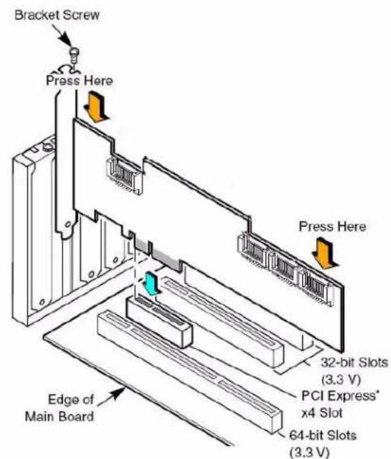
Figure 1. Inserting the Intel® RAID Controller SASWT4I into a PCI Express* Slot
- Connect the SAS/SATA cables from the backplane (or hard drives) to the RAID Controller (see Figure 2). Make sure the cables are properly connected to the controller.
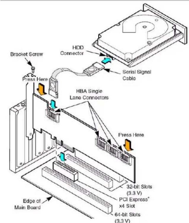
Figure 2. Attaching cables to the Intel® RAID Controller SASWT4I
Note: System throughput problems can occur if non-standard SAS cables are used. To minimize the potential for problems:
Use cables no longer than ten meters for SAS and one meter for SATA. It is better to use the shortest possible cables. The cable length should be reduced by about one foot (.33 meters) if using a backplane.
You may connect one device per SATA/SAS cable either as a device or as an expander.
Route SAS cables carefully.
◆Use only “straight” SAS cables, not “cross-over” SAS cables.
-
Replace components you needed to remove to access the PCI Express* add-in card slot. For instructions, see your server chassis documentation.
-
Reinstall the chassis cover and reconnect the power cord(s). For instructions, see your server chassis documentation for instructions.
-
Reconnect any peripheral items you needed to disconnect.
-
Turn the power on to the server and hard drives. As the server powers up, listen to be sure that the SAS and SATA devices are powered up before or at the same time as the computer boots.
-
Watch the boot process until you see a BIOS message informing you of the key combination that you need to press in order to enter the LSI Corporation MPT SAS BIOS Configuration Utility*. A message similar to the following appears:
Press
This message times out after several seconds. If you miss it, you will pass the option to get into the LSI Corporation MPT SAS BIOS Configuration Utility*.
The firmware takes several seconds to initialize and then displays the Intel ^® RAID Controller SASWT4I number and firmware version. The numbering of the controllers follows the PCI slot scanning order used by the server board.
Connecting the Cables
This section describes the cables used on the SAS controller and provides instructions for connecting SAS and SATA hard disk drives to the SAS RAID controller.
Note: Use only "straight" SAS cables, not "cross-over" SAS cables.
A SATA connector consists of a signal connector and a power connector. The SAS connector adds a bridge (primary physical link) between the signal connector and the power connector. This means SAS backplane connectors can accept either drive type, but SATA backplane connectors can ONLY accept SATA drives. Figure 3 shows these connectors.
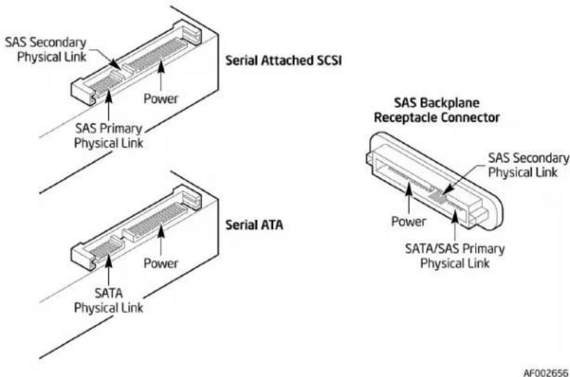
Figure 3. SAS and SATA Plugs and SAS Backplane Connector
Configuring the Storage Adapter
After performing the Intel ^® RAID Controller SASWT4I installation, you must configure the storage adapter and install the operating system driver. The Intel ^® IT/IR RAID Software User's Guide provides configuration options and instructions for the Intel ^® RAID Controller SASWT4I, as well as detailed installation instructions for operating system drivers.
Replacing a Controller
To replace a failed controller, follow these steps:
- Power off the computer, all drives, enclosures, and system components. Remove the power cord.
- Remove the chassis cover and access the PCI Express* add-in card slots. For instructions, see your server documentation.
- Disconnect the cable(s) from the RAID controller.
- Remove the failed controller from the system.
- Insert the replacement controller into the system. For instructions, see "Installing the RAID Controller".
3 Intel ^® RAID Controller SASWT4I Characteristics
This chapter describes the characteristics of the Intel ^® RAID Controller SASWT4I. Figure 4 displays the connectors and headers on the controller and Table 1 describes them.
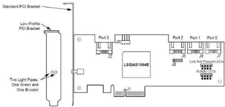
Figure 4. Card Layout
Table 1. Jumper Descriptions
| Jumper | Description Type Comments | ||
| J1 Lane | board edge connector | PCI Express* x4 | PCI Express X4 Slot or larger compatible |
| J2 SATA | internal right-angle connectors | SATA Connection to SAS/SATA devices | |
| J3 Right | angle, 0.1-inch pitch, pin header | 4-pin header | For driving external activity LEDs |
| J5-J7 SATA | internal right-angle connectors | SATA Connection to SAS/SATA devices | |
| J8 Debug | header 4-pin | header | For factory use |
Technical Specifications
The design and implementation of the Intel ^® RAID Controller SASWT4I minimizes electromagnetic emissions, susceptibility to radio frequency energy, and the effects of electrostatic discharge.
Table 2 lists the specifications for the Intel ^ RAID Controller SASWT4I.
Table 2. Specifications
| Specification Intel | ^® RAID Controller SASWT4I |
| Operating Voltage +3.3 | V, +12 V |
| Card Size Low-profile M | MD2 PCI Express* adapter card size (6.600 inches by 2.713 inches) |
| Array Interface to Host | PCI Express* Rev 1.0A, x4 lane width 2.5 Gbps |
| SAS Bus Speed 3 GBps per port, point-to-point | |
| SAS Controller One LSI* | SAS 1064E controller |
| SAS / SATA Ports 4 internal ports | |
| Firmware 2 MB in reflashable flash ROM | |
| Compatible Devices | Mixed capacity, mixed SATA II and SAS in different enclosuresNon-disk devices, including expanders |
| Cabling | Small, thin cables that do not restrict airflowShared connectors for multiple drive types |
| Redundant Configuration | RAID configuration is stored and config on disk (COD) |
| Enclosure Management | In-band SES enclosure management support, including fault LEDs(Expander backplane must be used in order to support fault LED. No fault LED option is possible or expected in direct HDD connect mode). |
LEDs
The host adapters have four LEDs, labeled A0–A3, that turn green to indicate an activity condition on any of the four phys. There are four LEDs, labeled LNP0–LNP3, that turn yellow to indicate a fault condition on any of the four phys. See Figure 4 for LED locations.
The host adapters have two light pipes routed through the PCI bracket:
- One light pipe turns green to indicate activity on any phy.
- The other light pipe is bi-color. It flashes green to indicate the adapter heartbeat, or it turns yellow when the adapter firmware detects a fault condition.
Array Performance Features
Table 3 lists the Intel ^ RAID Controller SASWT4I array performance features.
Table 3. Array Performance Features
| Specification Intel | ®RAID Controller SASWT4I |
| PCI Express* Host Data Transfer Rate | 2.5 Gigabit/s per lane |
| Drive Data Transfer Rate | 3 Gigabit/s per lane |
| Maximum Queue Tags per Drive | As many as the drive can accept |
| Stripe Sizes 64 Kbyte | |
| Background Services Rebuild | |
| Cache Options Disk cache enabled/disabled | |
Fault Tolerance
Table 4 lists the Intel ^ RAID Controller SASWT4I fault tolerance features.
Table 4. Fault Tolerance Features
| Specification Intel | ®RAID Controller SASWT4I |
| Drive Replacement Auto | detection of hard drive failure; hot-plug, hot-swap. |
| Drive Rebuild Using Hot Spares | Automatic at drive failure; auto-resume of initialization or rebuild on reboot |
| Error Checking and Indication | Parity generation and checking, activity and fault LEDs |
| Power Conservation Staggered spin-up, lower power requirements. | |
Electrical Characteristics
This section provides the power requirements for the Intel ^® RAID Controller SASWT4I. Table 5 lists the maximum power requirements.
Table 5. Electrical Characteristics
| PCI / PCI Express* /Express +12 V | PCI PRSNT1# / 2#Power | Operating RangeTemperature |
| 0.5A 6 W 0°C to 60°C |
Thermal and Atmospheric Characteristics
The thermal and atmospheric characteristics are:
• Temperature range from 0°C to 60°C (dry bulb).
- Relative humidity range: 5% to 90% non-condensing
• Maximum dew point temperature: 32°C
The storage and transit environment conditions are:
• Temperature range from -45^ to 105^ (dry bulb).
- Relative humidity range: 5% to 90% non-condensing
Safety Characteristics
The Intel ^® RAID Controller SASWT4I meets or exceeds the requirements of UL flammability rating 94 V0. Each bare board is also marked with the supplier name or trademark, type, and UL flammability rating. For the boards installed in a PCI Express* bus slot, all voltages are lower than the SELV 42.4 V limit.
The design and implementation minimize electromagnetic emissions, susceptibility to radio frequency energy, and the effects of electrostatic discharge. The board carries the CE mark, C-Tick mark, Canadian Compliance Statement, Korean MIC, Taiwan BSMI, Japan VCCI, FCC Class B and is marked with the FCC Self-Certification logo. The board also meets the requirements of CISPR Class B.
Appendix A: Glossary of Terms and Abbreviations
| BIOS | Basic Input/Output System. Software that provides basic read/write capability. Usually kept as firmware (ROM based). The system BIOS on a server board is used to boot and control the system. The BIOS on your host adapter acts as an extension of the system BIOS. |
| Configuration | The way a computer is set up; the combined hardware components (computer, monitor, keyboard, and peripheral devices) that make up a computer system, and the software settings that allow the hardware components to communicate with each other. |
| Device Driver | A program that allows a microprocessor (through the operating system) to direct the operation of a peripheral device. |
| Domain Validation | A software procedure in which a host queries a device to determine its ability to communicate at the negotiated data rate. |
| EEPROM Electronically Erasable Programmable Read-Only Memory. A memory chip typically used to store configuration information. It provides stable storage for long periods without electricity and can be reprogrammed. See NVRAM. | |
| External SAS Device | A SAS device installed outside the computer cabinet. These devices are connected together using specific types of shielded cables. |
| Host | The computer system in which a storage adapter is installed. It uses the storage adapter to transfer information to and from devices attached to the SCSI bus. |
| Host Adapter Board (HAB) | A circuit board or integrated circuit that provides a device connection to the computer system. |
| Internal SAS Device | A SAS device installed inside the computer cabinet. These devices are connected together using an unshielded ribbon cable. |
| Main Memory | The part of a computer's memory that is directly accessible by the CPU (usually synonymous with RAM). |
| NVRAM | Non-volatile Random Access Memory. An EEPROM (Electronically Erasable Read-Only Memory chip) used to store configuration information. See EEPROM. |
| Peripheral Devices | A piece of hardware (such as a video monitor, disk drive, printer, or CD-ROM) used with a computer and under the computer's control. SCSI peripherals are controlled through a SAS Intel ^ RAID Controller SASWT4I. |
SAS
Serial-attached SCSI. A serial, point-to-point, enterprise-level device interface that leverages the proven SCSI protocol set. The SAS interface provides improved performance, simplified cabling, smaller connections, lower pin count, and lower power requirements when compared to parallel SCSI. SAS controllers leverage a common electrical and physical connection interface that is compatible with Serial ATA. The SAS controllers support the ANSI Serial Attached SCSI standard, version 1.0. In addition, the controller supports the Serial ATA (SATA) protocol defined by the Serial ATA specification, version 1.0a. Each port on the SAS RAID controller supports SAS and SATA devices.
SAS Device
Any device that conforms to the SAS standard and is attached to the SAS bus by a SAS cable. This includes SAS storage adapters (host adapters) and SAS peripherals.
- Intel® RAID Controller SASWT4I Hardware User's Guide
- DISCLAIMER
- Audience
- Organization
- Related Publication
- Table of Contents
- Preface ....iii
- Chapter 1: Overview ....1
- Chapter 2: Intel ® RAID Controller SASWT4I Hardware Installation ....5
- Chapter 3: Intel ® RAID Controller SASWT4I Characteristics ..... 11
- Appendix A: Glossary of Terms and Abbreviations 15
- List of Figures
- List of Tables
- Summary of SAS RAID Controller Features
- Usability
- Redundancy and Error Handling
- SAS and SATA Features
- Operating System Support
- Benefits of Serial-Attached SCSI (SAS)
- Intel ® RAID Controller SASWT4I Hardware Installation
- Requirements
- Installing the RAID Controller
- Connecting the Cables
- Configuring the Storage Adapter
- Replacing a Controller
- Intel ® RAID Controller SASWT4I Characteristics
- Technical Specifications
- LEDs
- Array Performance Features
- Fault Tolerance
- Electrical Characteristics
- Thermal and Atmospheric Characteristics
- Safety Characteristics
- Appendix A: Glossary of Terms and Abbreviations
- SAS
- SAS Device
Brand : INTEL
Model : SASWT4I
Category : Controller