
Total Control MRX-5 - Remote control URC - Free user manual and instructions
Find the device manual for free Total Control MRX-5 URC in PDF.


| Type | Advanced Network System Controller |
| Brand | URC |
| Model | Total Control MRX-5 |
| Processor | ARM9 Thumb Processor 400 MHz |
| RAM | DDR2 256 MB |
| Storage | e.MMC NAND 4 GB |
| Network | 1x 10/100 RJ45 Ethernet |
| IR Outputs | 4x 3.5mm (IR attenuator on output 4) |
| RS-232 Port | 1x (Tx, Rx, GND) |
| USB Port | 1x (for future use) |
| Power Supply | DC 12V / 1.0A (adapter included) |
| Weight | 6 oz (170 g) |
| Mounting | Wall mount plate and rack-mount ears included |
| Compatibility | Only Total Control software, products, and user interfaces |
| LED Indicators | Power (blue solid/blinking/off), Network (blue solid/blinking/off) |
| Reset | Single tap to reboot; press and hold 15 seconds for factory reset |
| Included Accessories | 4x IR emitters, AC power adapter, wall mount plate with screws, rack-mount ears |
| Certifications | CE, FCC Class B |
Frequently Asked Questions - Total Control MRX-5 URC
User questions about Total Control MRX-5 URC
0 question about this device. Answer the ones you know or ask your own.
Ask a new question about this device
Download the instructions for your Remote control in PDF format for free! Find your manual Total Control MRX-5 - URC and take your electronic device back in hand. On this page are published all the documents necessary for the use of your device. Total Control MRX-5 by URC.
USER MANUAL Total Control MRX-5 URC
MRX-5 OWNER'S MANUAL

MRX-5
OWNER'S MANUAL

TOTAL CONTROL
MRX-5 OWNER'S MANUAL
Table of Contents
Introduction 1
Front Panel Description 2
Rear Panel Description ....3
Bottom Panel Description....4
Installing the MRX-5 5
Network Installation....5
Connecting IR Emitters....6
Connecting RS-232 (Serial)....7
Specifications 8
Limited Warranty Statement......8
Rev 1.0

Technical Support
Toll Free: 800-904-0800
Main: 914-835-4484
techsupport@urc-automation.com
Hours: 9:00 am - 5:00 pm ESTM
TOTAL CONTROL
MRX-5 OWNER'S MANUAL
Introduction
The MRX-5 Advanced Network System Controller controls is designed to meet the needs of residential or small commercial environments.
Only Total Control software, products, and user interfaces are supported by this powerful device.
This device is not compatible with Total Control 1.0 legacy products.
Features and Benefits
• Stores and issues commands for all IP, IR, and RS-232 controlled devices.
- Provides two-way communication with Total Control user interfaces. (remotes and keypads).
- Easy rack-mounting via the included rack mounting ears.
Parts List
The MRX-5 Advanced Network Controller includes:
• 1x MRX-5 System Controller
• 4x IR Emitters 3.5mm (standard)
- 1x AC Power Adapter
• Wall Mount and 4x Screws

natural_image
Exterior view of a modern office building (no signage)

TOTAL CONTROL
MRX-5 OWNER'S MANUAL
Front Panel Description
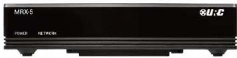
The front panel of the MRX-5 Advanced Network System Controller displays the following information:
- Power LED: Indicates three (3) possible states:
■ Solid Blue: The device is receiving power and has successfully booted up.
■ Blinking Blue: The device is receiving power, but is still initializing.
■ Off: The device is not receiving power.
- Network LED: Indicates three (3) possible states:
■ Solid Blue: The device is connected to the network and has received an IP address.
■ Blinking Blue: The device is connected to the network, but has not yet received an IP address.
This LED blinks blue after a Total Control configuration file has been downloaded to the device.
■ Off: The device is not connected to the local network.

TOTAL CONTROL
MRX-5 OWNER'S MANUAL
Rear Panel Description
The rear panel of the MRX-5 Advanced Network System Controller displays the following information:
- DC 12V: Connect the supplied power adapter to this port, the Power LED becomes solid blue when the device has received power.
- IR Outputs: Four (4) standard 3.5mm IR emitter ports. IR Output 4 provides variable level adjustment.
- RS-232 Port: One (1) RS-232 ports support Tx(Transmit), Rx(Receive) and GND(Ground) connections for two way communication.
Compatible with URC cables RS232F and RS232M.
- USB Port: Designed for future use.
- LAN Port: RJ45 standard 10/100 Ethernet connection to the local network.

TOTAL CONTROL
MRX-5 OWNER'S MANUAL
Bottom Panel Description
The bottom panel of the MRX-5 Advanced Network System Controller displays the following information:
- Reset Button: Located at the bottom of the device and requires a stylus or paper clip to press. Performs two (2) possible actions:
■ Single Tap: Power cycle the device.
■ Press-N-Hold: Press this button for 15 seconds to restore the device to its factory settings. This action cannot be reversed and the device REQUIRES re-programming with the Total Control software.
- Mounting Plate: Slide the mounting plate up or down to remove it from the device. Use the four (4) supplied mounting screws to mount the MRX-5 on a wall, ceiling, or any other convenient location.

natural_image
Top-down view of a mechanical component with mounting holes and a highlighted square component (no text or symbols)TOTAL CONTROL
MRX-5 OWNER'S MANUAL
Installing the MRX-5
The MRX-5 Advanced Network System Controller can be installed almost anywhere in the home.
Once physically installed, it requires programming by a certified URC integrator in order to operate local equipment using IP (Network), RS-232 (Serial), IR (Infrared), or relays. All cables must be connected to their respective ports at the rear of the device.
Network Installation
- Connect an Ethernet cable (RJ45) to the rear of the MRX-5 and the onto an available LAN port of the network's local router (Luxul preferred).
- A certified URC integrator is required for this step, configure the MRX-5 to a DHCP/MAC reservation within the local router.

TOTAL CONTROL
MRX-5 OWNER'S MANUAL
Connecting IR Emitters
IR emitters are used to communicate to AV devices such as cable boxes, televisions, blu-ray players and more.
- Plug IR Emitters (four (4) supplied in the box) into any of the four (4) IR outputs available on the rear of the MRX-5.
IR Output 4 includes an adjustable sensitivity dial. Turn this dial to the right to increase the gain and to the left to decrease it. - Remove the adhesive covering from the emitter and place it over the IR receiver of the 3rd party device (cable box, television, etc.).


natural_image
Modern flat-screen TV displaying a scenic road at sunset with no visible text or symbols on the screen or stand.TOTAL CONTROL
MRX-5 OWNER'S MANUAL
Connecting RS-232 (Serial)
The MRX-5 can operate equipment via RS-232 communication. The allows discrete serial commands to be triggered from the Total Control system.
Connect an RS-232 device using URC's proprietary RS-232 cables. These use either male or female DB-9 connections with standard pin-outs.
- Connect the 3.5mm into the RS-232 Output available on the MRX-5.
- Connect the Serial connection onto the available port on the 3rd party device, such as AVRs, Televisions, Matrix Switchers, and other devices.


TOTAL CONTROL
MRX-5 OWNER'S MANUAL
Specifications
Network: One (1) 10/100 RJ45 Ethernet port (two LED indicators)
Processor: ARM9 Thumb Processor 400 MHz
RAM: DDR2 256 MB
Storage: e.MMC NAND 4GB
Weight: 6 oz
Power: DC 12V/1.0A
IR Outputs: Four (4) IR outputs (IR attenuator on output 4)
RS-232: One (1) RS-232 port
USB Port: For Future Use
Limited Warranty Statement
https://www.urc-automation.com/legal/warranty-statement/
End User Agreement
The terms and conditions of the End User Agreement available at https://www.urc-automation.com/legal/end-user-agreement/shall apply.
Federal Communication Commission Interference Statement
This equipment has been tested and found to comply with the limits for a Class B digital device, pursuant to part 15 of the FCC Rules. These limits are designed to provide reasonable protection against harmful interference in a residential installation. This equipment generates, uses and can radiate radio frequency energy and, if not installed and used in accordance with the instructions, may cause harmful interference to radio communications. However, there is no guarantee that interference will not occur in a particular installation. If this equipment does cause harmful interference to radio or television reception, which can be determined by turning the equipment off and on, the user is encouraged to try to correct the interference by one more of the following measures:
• Reorient or relocate the receiving antenna.
- Increase the separation between the equipment and receiver.
- Connect the equipment into an outlet on a circuit different from that to which the receiver is connected.
- Consult the dealer or an experienced radio/TV technician for help.
TOTAL CONTROL

MRX-5
OWNER'S MANUAL
Warning!
The manufacturer is not responsible for any Radio or TV interference caused by unauthorized modifications to this equipment.
Changes or modifications not expressly approved by the manufacturer could void the user's authority to operate the equipment.
Regulatory Information to the User
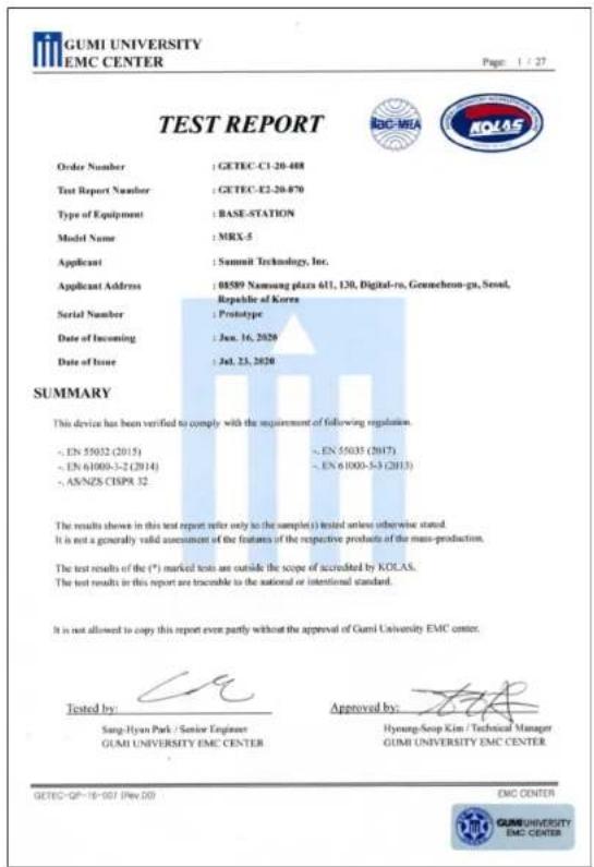
- CE conformity Notice Products with "CE" marking comply EMC Directive 2014/30/EU issued by the commission of the European Community.
-
EMC Directive
-
Emission
- Immunity
- Power
- Declaration of Conformity
"Hereby, Universal Remote Control Inc. declares that this MRX-5 is in compliance with the Essential requirements."
- MRX-5 OWNER'S MANUAL
- MRX-5
- OWNER'S MANUAL
- TOTAL CONTROL
- Table of Contents
- Technical Support
- Introduction
- Features and Benefits
- Parts List
- Front Panel Description
- Rear Panel Description
- Bottom Panel Description
- Installing the MRX-5
- Network Installation
- Connecting IR Emitters
- Connecting RS-232 (Serial)
- Specifications
- Limited Warranty Statement
- End User Agreement
- Federal Communication Commission Interference Statement
- Warning!
- Regulatory Information to the User
Brand : URC
Model : Total Control MRX-5
Category : Remote control