ZTW900PSNSS - Warming Drawer Monogram - Free user manual and instructions
Find the device manual for free ZTW900PSNSS Monogram in PDF.


| Product Type | Warming Drawer |
| Brand | Monogram |
| Model | ZTW900PSNSS |
| Width | 30 inches |
| Height | 7 inches |
| Depth | 22 inches |
| Weight | 35 lbs |
| Power Supply | 120 V, 60 Hz, 600 W |
| Main Functions | Keep Warm, Proof, Slow Cook |
| Temperature Range | 100°F - 200°F |
| Capacity | Fits multiple serving dishes |
| Material | Stainless Steel |
| Control Type | Electronic Touch Controls |
| Cleaning | Wipe with damp cloth, mild detergent |
| Safety Features | Auto shut-off, child lock |
| Spare Parts Availability | Yes, through Monogram service |
| Installation | Built-in under counter |
| Warranty | 2 Year Limited Warranty |
| Frequency | 60 Hz |
| Voltage | 120 V |
| Power Consumption | 600 W |
| Certifications | UL, Energy Star |
Frequently Asked Questions - ZTW900PSNSS Monogram
User questions about ZTW900PSNSS Monogram
0 question about this device. Answer the ones you know or ask your own.
Ask a new question about this device
Download the instructions for your Warming Drawer in PDF format for free! Find your manual ZTW900PSNSS - Monogram and take your electronic device back in hand. On this page are published all the documents necessary for the use of your device. ZTW900PSNSS by Monogram.
USER MANUAL ZTW900PSNSS Monogram
Electric Warming Drawer
ZKW700S, ZKW700P, ZTW900S and ZTW900P
Read these instructions completely and carefully.
■ IMPORTANT — Save these instructions for local inspector's use.
■ IMPORTANT — Observe all governing codes and ordinances.
■ Note to Installer – Be sure to leave these instructions with Consumer.
■ Note to Consumer – Keep these instructions for future reference.
■ Completion Time — 1 to 3 Hours.
- Proper installation is the responsibility of the installer. Product failure due to improper installation is not covered under the warranty. See Owner's Manual for warranty information.
■ Use this appliance only for its intended purpose.
- Check with local utilities for electrical codes that apply in your area. Local codes vary. Installation electrical connections and grounding must comply with applicable codes. In the absence of local codes, the drawer should be installed in accordance with National Electrical Code ANSI/NFPA 70-1990 or latest edition.
WARNING
■ This appliance must be properly grounded. See "Grounding the Appliance."
■ Insure that the power cord does not contact the hot surface on the bottom of ovens, cooktops, or other appliances.
■ If you received a damaged warming drawer, you should contact your dealer
■ For Monogram local service in your area, 1.800.444.1845.
■ For Monogram Service in Canada, call 1.800.561.3344.
■ For Monogram Parts and Accessories, call 1.800.626.2002.
MODELS AVAILABLE
30" Models: ZTW900S, ZTW900P
27" Models: ZKW700S, ZKW700P
WARNING
An anti-tip brace must be installed to prevent the drawer from tipping forward when opened and loaded. Failure to do so could result in personal injury.
CONTENTS
Design Information
Models Available 2
Accessories 2
Product Dimensions ....3
Grounding the Appliance ....3
Installation Preparation
Tools and Materials Required 4
Remove Packaging 4
Installation Options
Installation Below a Single Oven ....5
Installation Below a Double Oven ....5
Installation Below a Countertop 6
Provide Cabinet Support 7
Flushmount Installation Preparation .....7
Install Anti-Tip Brackets 8
Install Warming Drawer 8
Installation Instructions: Warming Drawer
Custom Panel Accessory Kit ZXW900 ....9
Before You Begin 9
Step 1, Prepare Drawer For Panel Installation ..9
Step 2, Remove Original Drawer Front .....9
Step 3, Prepare Custom Panel ....9
Step 4, Secure Custom Panel to Metal Mounting Panel ....10
Step 5A, For Panels Less Than 3/4" Thick .....10
Step 5B, For 3/4" (Or Greater) Thick Panels
Step 6, Install Lamp Jewel ....10
Step 7, Reinstall Original Handle or Optional Custom Handle ....10
Step 8, Install Assembled Panel to the Drawer ....10
FRONT PANEL ACCESSORIES
ZXW900
This kit provides for the installation of a custom front panel on 30" models.
NOTE: The original drawer front will be removed and discarded when this kit is used. The tubular handle can be reinstalled onto the custom panel with longer screws (not provided). Or, the original handle can be replaced with a custom handle of your choice. (Handle is not supplied.) Choose a custom handle to match or complement cabinetry hardware.
For more Accessories or purchasing information please refer to Assistance/Accessories section of Monogram Warming Drawer Owner's Manual.
Design Information
PRODUCT DIMENSIONS AND CLEARANCES
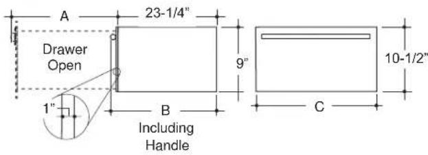
| Models | Dimensions | ||
| A | B | C | |
| ZTW900S and ZTW900P | 23-1/4" 25-1/4" 29-3/4" | ||
| ZKW700S and ZKW700P | 22-26" 26-1/4" 26-3/4" | ||
| ZXS900P and ZXW900 Dimensions to be determined by panel and handle | 29-3/4" | ||
GROUNDING THE APPLIANCE
Please read carefully.
Do not use an extension cord or adapter plug with this appliance. Follow National electrical codes or prevailing local codes and ordinances.
This warming drawer must be supplied with 120V, 60Hz, and connected to an individual, properly grounded branch circuit, and protected by a 15 or 20 amp circuit breaker or time delay fuse.
■ A properly grounded 3-prong receptacle should be located within reach of the drawers' 56" long power cord.
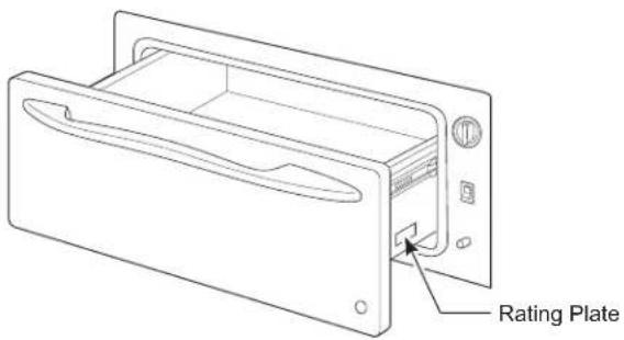
■ Locate the receptacle in an adjacent cabinet.
– within 42" of the right side or,
– within 16" of the left side or,
- A recessed receptacle may be located on the right side of the cutout, 7" from the back of the cabinet. In this location, the excess power cord should be coiled and taped to the right side of the unit.
■ When two warming drawers are installed side to side, they can operate from the same receptacle.
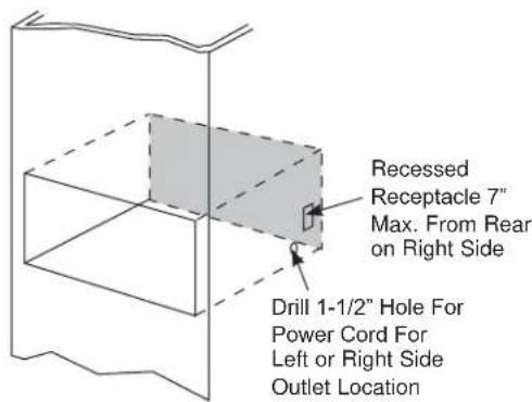
Please read carefully.
The power cord of this appliance is equipped with a 3-prong (grounding) plug that mates with a standard 3-prong grounding wall receptacle to minimize the possibility of electric shock. The customer should have the wall receptacle and circuit checked by a qualified electrician to make sure the receptacle is properly grounded and has the correct polarity.
■ Where a standard 2-prong wall receptacle is encountered, it is the personal responsibility and obligation of the customer to have it replaced with a properly grounded 3-prong wall receptacle.
Do not, under any circumstances, cut or remove the third (ground) prong from the power cord.
DO NOT USE AN EXTENSION CORD WITH THIS APPLIANCE.
FOLLOW NATIONAL ELECTRICAL CODES AND ORDINANCES.
Installation Preparation
TOOLS REQUIRED MATERIALS REQUIRED
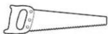
Hand Saw
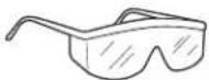
Safety Glasses
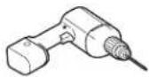
Drill and 1/16" Bit
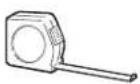
Measuring Tape

Phillips Screwdriver

Level
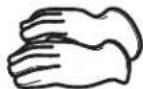
Cut Resistant Gloves
(provided)

4 Wood Screws
MATERIALS REQUIRED
(not provided)
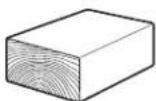
2x2 or 2x4
Wood Block
for Anti-Tip
Security
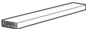
2x2 or 2x4
Lumber for
Runners
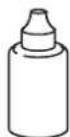
Adhesive or other hardware for installing runners or shelf to support warmer drawer
Runners must be level, rigidly mounted and capable of supporting 150 pounds.
REMOVE PACKAGING
Place Warming Drawer on carton or protective pad to prevent damage to drawer front or finished flooring.
INSTALLATION OPTIONS
Installation Below a Single Oven
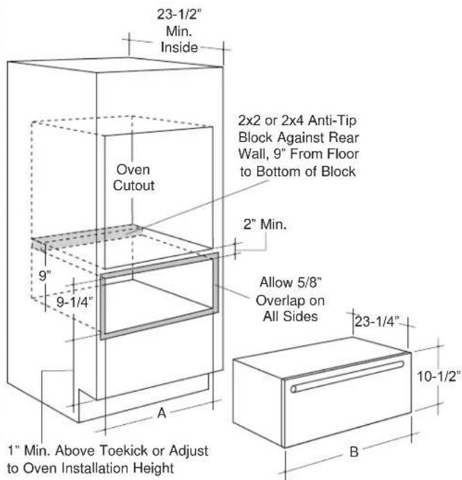
Installation Below a Double Oven
| Models | Dimensions | ||
| A | B | ||
| ZTW900S & ZTW900P | 28-1/2" | 29-3/4" | |
| ZKW700S &ZKW700P | 25-1/2" | 26-3/4" | |
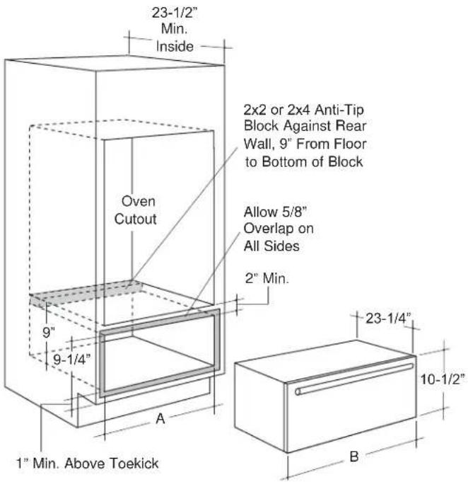
When installed under a wall oven:
Warming drawers are approved for installation below only certain specified wall oven models. See the label attached to the top of the warming drawer for approved models.
■ When installed, the front face of the drawer will be nearly flush with adjacent cabinetry doors.
- Drawer overlaps will conceal cut edges on all sides of the opening.
NOTE: Additional clearance between cutouts may be required. Check to be sure that oven supports above the Warming Drawer location does not obstruct the required interior 23-1/2" depth and 9-1/4" height.
The rough opening for the drawer must be:
■ Depth: 23-1/2" min. from inside back to front of cabinet frame.
■ Width: 25-1/2" for 27" wide models, 28-1/2" for 30" wide models.
■ Height: 9-1/4".
- Allow 2" min. between oven and drawer cutouts for clearance of overlaps.
NOTE: If you are installing in frameless cabinets, it may be necessary to install 1/2" wide cleats to accept drawer mounting screws. See drawer for mounting screw locations.
INSTALLATION BELOW A COUNTERTOP
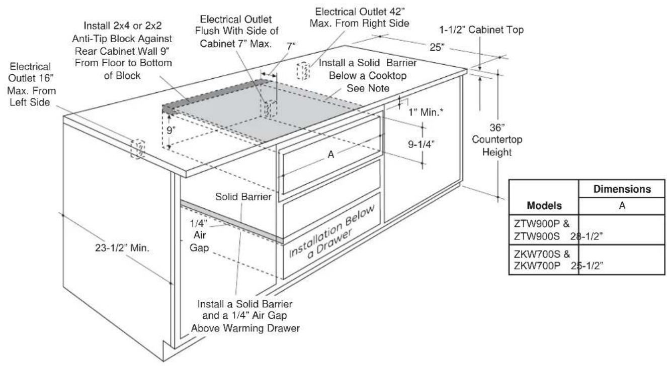
■ When installed, the front face of the drawer will be nearly flush with adjacent cabinetry doors.
- Drawer overlaps will conceal cut edges on all sides of the opening.
■ The rough opening for the drawer must be:
- Depth: 23-1/2" min. from inside back to front of cabinet frame.
- Width: 25-1/2" for 27" wide models, 28-1/2" for 30" wide models.
- Height: 9-1/4".
■ 5" min. above floor or 1" above toekick. 23-1/4" from floor to bottom of cutout is recommended for under countertop installation.
Installation below a cooktop:
Warming drawers are approved for installation below only certain specified cooktop models. See the label attached to the top of the warming drawer for approved models. A solid barrier and air gap between cooktop and warming drawer is required. See NOTE above.
*NOTE: When installing the warming drawer below a cooktop, a solid barrier must be installed at least 1" from the lowest point of the bottom of cooktop burner box to the top of cutout. Use any solid material such as 1/4" thick plywood. Allow at least 1/4" air gap between the barrier and the top of the warming drawer. See label on top of the warming drawer for approved cooktop models.
Installation below a cabinet drawer:
The warming drawer may be installed beneath a cabinet drawer. In this installation, a solid barrier should be installed above the warming drawer to block access. Use any solid material such as 1/4" thick plywood. Allow at least 1/4" air gap between the barrier and the top of the warming drawer. Observe the 5" min. above the floor or 1" above the toekick minimum installation height.
NOTE: If you are installing in frameless cabinets, it may be necessary to install 1/2" wide cleats to accept drawer mounting screws. See drawer to find exact locations of mounting screws.
Side to Side Installation:
Install two warming drawers in separate cutouts. Allow 2" min. between cutouts.

Installation Preparation
PROVIDE CABINET SUPPORT
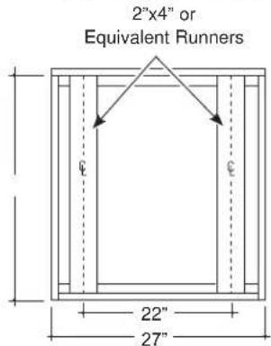
IMPORTANT: When installed below a single or double oven, check to be sure that any oven supports above the cutout do not obstruct the 23-1/2" required depth of the warming drawer cutout.
■ A 2" min. clearance between oven and warming drawer cutouts are required. Additional clearance may be required if 2 x 4 blocks are used to support runners or solid floor of the oven above.
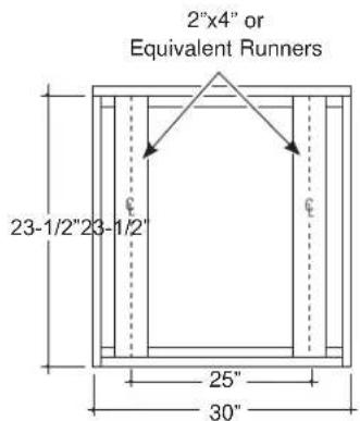
■ The warmer drawer may be supported by either a solid bottom, 2 x 4 or 2 x 2 runners.
■ The support must be level and rigidly mounted, flush with the bottom edge of the cutout.
— There is no way to level the drawer once it has been installed. Be sure supports are level.
■ The entire weight of the drawer is supported by the runners or solid floor and must be capable of supporting 150 lbs.
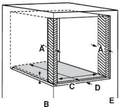
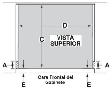
FLUSHMOUNT INSTALLATION PREPARATION
PREPARE THE INTERIOR
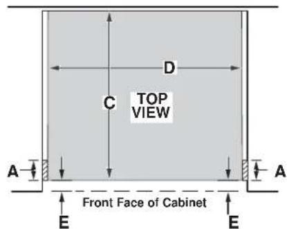
Cut and install side cleats:
- Cut side wood cleats to height of cabinet opening and approx. 2-1/2" in depth. Install, on each side, E from the front face of the cabinet.
Cut and install bottom cleat:
- Cut bottom wood cleat to a height of 1" minimum, a depth of the cabinet minus E and a width of the cabinet opening D.
Install onto the cabinet floor between the side cleats, push it all the way back against cabinet wall and make sure its front face aligns with the front faces of the side cleats (E gap from the front cabinet face).
| 30" 27" | |||
| A S | Side cleats depth 2-1/2" | min. 2-1/2" min. | |
| B E | Bottom cleat height 1" | min. 1" min. | |
| C E | Bottom cleat depth | Cabinet depth minus E | Cabinet depth minus E |
| D E | Bottom cleat width | 28 1⁄2" min. - 29" max. (30" minus 2 side cleat thicknesses of 5/8-3/4"each) | 25 1⁄2" min. - 26" max. (27" minus 2 side cleat thicknesses of 5/8-3/4" each) |
| E | All three cleats inset from cabinet front | 1-3/8" | 1-3/8" |
INSTALL ANTI-TIP BRACKETS
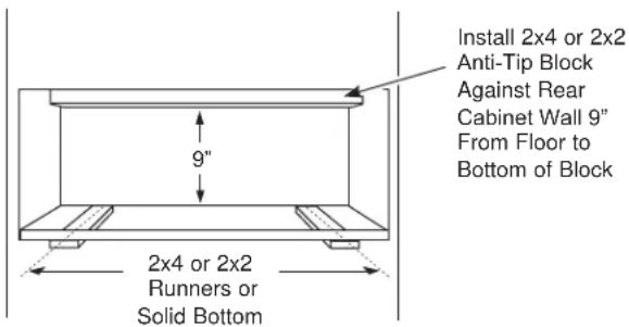
WARNING
ANTI-TIP PRECAUTIONS
An anti-tip brace must be installed to prevent the drawer from tipping forward when opened and loaded. Failure to do so could result in personal injury.
INSTALL WARMING DRAWER
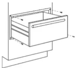
■ Slide the left corner of the drawer into the opening.
■ Push the power cord into the hole leading to the outlet location. Thread the cord through as the drawer is being pushed back into the opening. Check to be sure the power cord does not get trapped under the drawer.
- If the outlet is installed inside the opening, plug the cord into the outlet. In this location, the excess power cord length should be coiled and taped to the right side of the unit.
■ Push the drawer back until the front flange is flush to the cabinet front.
■ Open the drawer fully.
■ Drill pilot holes through the holes in the overlapping frame, one on each corner.
■ Drive the wood screws provided into each corner.
natural_image
Line drawing of a drawer with handle and drawer slot, no text or symbols presentInstallation Instructions
WARMING DRAWER CUSTOM PANEL ACCESSORY KIT
ZXW900
For installation of 30" wide warming drawer custom panel and custom handle.
BEFORE YOU BEGIN
Read these instructions completely and carefully.
- IMPORTANT – Save these instructions for local in spec tor's use.
■ IMPORTANT – Observe all governing codes and ordinances.
■ Note to Installer – Be sure to leave these instructions with the consumer.
■ Note to Consumer – Keep these instructions for future reference.
■ Skill level – Installation of this custom panel kit requires a qualified installer or service technician.
■ Proper installation is the responsibility of the installer.
■ Product failure due to improper installation is NOT covered under the warranty.
TOOL AND MATERIALS REQUIRED
■ Safety glasses
■ Cut resistant gloves
■ Phillips screwdriver
■ Drill and appropriate bits (Brad point recommended for drilling through wood panels)
■ Custom panel
■ Custom handle (optional)
■ Adhesive recommended for metal to wood
■ Adhesive recommended for plastic to wood
PARTS SUPPLIED
■ Lamp Jewel
■ Metal mounting panel
■ Bag of #6 size screws
This kit contains a mounting panel to support a trimless custom drawer front up to 3/4" thick. The tubular handle can be reinstalled onto the custom panel with longer screws (not provided). Or, the original handle can be replaced with a custom handle of your choice. (Handle is not supplied.) Choose a custom handle to match or complement cabinetry hardware.
IMPORTANT: The warming drawer should be installed according to the installation instructions packed with the product. The original drawer front will be removed and replaced with a custom panel.
- Cut edges of the drawer panel will be seen and must be finished for best appearance.
■ The custom drawer front panel, both raised and flat design, should be constructed in the same manner as typical cabinet doors.
■ Order the custom drawer panel from the cabinet manufacturer. Be sure to provide the exact dimensions so that the panel is constructed accurately.
■ Order the optional custom handle to complement or match surrounding cabinetry handles.
1 PREPARE DRAWER FOR PANEL INSTALLATION
■ Open the drawer fully.
■ Turn the warming drawer off.
2 REMOVE ORIGINAL DRAWER FRONT
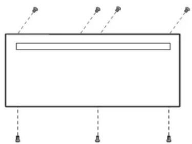
- Remove seven #8 screws. Remove four from top inside and three from bottom. Set these screws aside – they are no longer needed.
■ Support the drawer front as you remove screws to prevent the possibility of falling.
natural_image
Simple line drawing of a rectangular frame with three vertical supports and two small circular markers at the bottom (no text or symbols)3 PREPARE CUSTOM PANEL
■ The custom panel size is determined by the cabinetry dimensions and spacings.
■ Once the custom panel size is determined, place the metal panel on the custom panel and check the squareness and correct placement of the metal panel, and mark the hole for the indicator light. Confirm that the hole marking provides the indicator light to the right side of the custom panel appearance side.
- Drill a 5/16" hole. A Brad point drill bit is recommended.
4 SECURE CUSTOM PANEL TO METAL MOUNTING PANEL
■ Lay the custom panel, appearance side down, on a clean surface.
■ Remove all tape and packing material from the metal panel.
■ Place the flat side of the metal panel onto the back side of the custom panel, with the mounting flanges facing up.
■ Align the lamp hole in the panel with the mounting panel.
■ Confirm squareness and correct position of the metal panel to the custom panel.
5A FOR PANELS LESS THAN 3/4" THICK
■ Separate the custom panel and metal panel.
■ Apply a few horizontal beads of adhesive to the metal panel. Avoid adhesive within 1" of lamp hole area and outer edges.
5B FOR 3/4" (OR GREATER) THICK PANELS
■ Separate the custom panel and metal panel.
■ Use the metal panel as a template. Position the metal panel over the back side of the custom panel and drill pilot holes. Drill pilot holes sized to match screws being used (screws not provided).
NOTE: Select screw length carefully to avoid penetration of the finished side.
6 INSTALL LAMP JEWEL
■ Turn the assembly appearance side up.
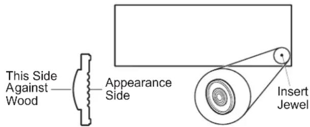
■ Use plastic to wood adhesive to secure the lamp jewel to the front of the wood panel. On the side with the bulge, (see illustration) apply a small bead of adhesive around the outside edge. Place the jewel into the drilled hole.
7 REINSTALL ORIGINAL HANDLE OR OPTIONAL CUSTOM HANDLE
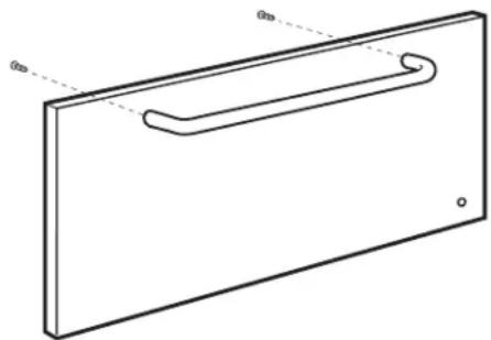
■ A custom handle (not supplied) may be installed.
- Drill pilot holes through the front of the custom panel and through the metal panel to match the chosen handle.
NOTE: The handle screws should be installed through the metal panel, the custom panel and into the custom or original handle.
natural_image
Simple line drawing of a rectangular panel with a handle and side markers (no text or symbols)8 INSTALL ASSEMBLED PANEL TO THE DRAWER
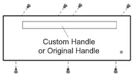
■ Determine which holes in the metal panel line up with the holes in the exposed drawer front and marked the screw hole locations onto the custom panel.
- Drill 1/8" deep holes into the custom panel for clearance to the #6 screws. The #6 screws will extend into the custom panel slightly.
■ Using the #6 screws supplied in the bag, install the custom panel assembly to the exposed drawer front with seven screws.
■ The original #8 screws are not needed.
NOTE: Product improvement is a continuing endeavor at Monogram Appliances. Therefore, materials, appearance and specifications are subject to change without notice.
NOTE: While performing installations described in this book, safety glasses or goggles should be worn.
For Monogram ^® local service in your area, call 1.800.444.1845.
NOTE: Product improvement is a continuing endeavor at GE Appliances. Therefore, materials, appearance and specifications are subject to change without notice.

MONOGRAM
INSTALE LOS SOPORTES ANTI VOLCADURAS
ADVERTENCIA
PRECAUCIONES ANTI
VOLCADURAS:
natural_image
Line drawing of a wooden drawer or drawer cabinet with no text or symbolsnatural_image
Simple line drawing of a rectangular frame with three vertical supports and two small circular markers at the bottom (no text or symbols)3 PREPARE EL PANEL A MEDIDA
natural_image
Simple line drawing of a rectangular door with a handle and side panel (no text or symbols)- WARNING
- MODELS AVAILABLE
- CONTENTS
- FRONT PANEL ACCESSORIES
- ZXW900
- Design Information
- PRODUCT DIMENSIONS AND CLEARANCES
- GROUNDING THE APPLIANCE
- Please read carefully.
- DO NOT USE AN EXTENSION CORD WITH THIS APPLIANCE.
- Installation Preparation
- REMOVE PACKAGING
- INSTALLATION OPTIONS
- When installed under a wall oven:
- The rough opening for the drawer must be:
- Installation below a cooktop:
- Installation below a cabinet drawer:
- Side to Side Installation:
- FLUSHMOUNT INSTALLATION PREPARATION
- PREPARE THE INTERIOR
- Cut and install side cleats:
- Cut and install bottom cleat:
- INSTALL ANTI-TIP BRACKETS
- ANTI-TIP PRECAUTIONS
- INSTALL WARMING DRAWER
- Installation Instructions
- WARMING DRAWER CUSTOM PANEL ACCESSORY KIT
- BEFORE YOU BEGIN
- TOOL AND MATERIALS REQUIRED
- PARTS SUPPLIED
- PREPARE DRAWER FOR PANEL INSTALLATION
- REMOVE ORIGINAL DRAWER FRONT
- PREPARE CUSTOM PANEL
- SECURE CUSTOM PANEL TO METAL MOUNTING PANEL
- 5A FOR PANELS LESS THAN 3/4" THICK
- 5B FOR 3/4" (OR GREATER) THICK PANELS
- INSTALL LAMP JEWEL
- REINSTALL ORIGINAL HANDLE OR OPTIONAL CUSTOM HANDLE
- INSTALL ASSEMBLED PANEL TO THE DRAWER
- INSTALE LOS SOPORTES ANTI VOLCADURAS
- ADVERTENCIA
- PREPARE EL PANEL A MEDIDA
Brand : Monogram
Model : ZTW900PSNSS
Category : Warming Drawer