
P100N - Document Camera Elmo - Free user manual and instructions
Find the device manual for free P100N Elmo in PDF.


| Product Type | Document Camera |
| Brand | Elmo |
| Model | P100N |
| Dimensions (L x W x H) | Approx. 400 x 300 x 100 mm |
| Weight | Approx. 2.5 kg |
| Power Supply | AC adapter 100-240V, 50/60Hz |
| Image Sensor | 1/2.3-inch CMOS |
| Resolution | Full HD 1080p (1920x1080) |
| Optical Zoom | 10x |
| Digital Zoom | 8x |
| Connectivity | USB 2.0, HDMI out, VGA out |
| Lighting | Built-in LED lamp |
| Functions | Document capture, image capture, video recording, annotation, split screen |
| Maintenance | Clean lens with soft, dry cloth; wipe body with damp cloth |
| Safety Precautions | Keep away from water; use only supplied AC adapter; avoid direct sunlight |
| Spare Parts | AC adapter, USB cable, remote control (optional) |
| Reparability | Contact Elmo service center for repairs; do not disassemble |
| General Information | Designed for education and business presentations |
Frequently Asked Questions - P100N Elmo
User questions about P100N Elmo
0 question about this device. Answer the ones you know or ask your own.
Ask a new question about this device
Download the instructions for your Document Camera in PDF format for free! Find your manual P100N - Elmo and take your electronic device back in hand. On this page are published all the documents necessary for the use of your device. P100N by Elmo.
USER MANUAL P100N Elmo
Please read this instruction manual carefully before using this product and keep it for future reference.
IMPORTANT SAFEGUARDS
- Read Instructions – All the safety and operating instructions should be read before the appliance is operated.
■ Retain Instructions – The safety and operating instructions should be retained for future reference.
■Heed Warnings – All warnings on the product and in the operating instructions should be adhered to.
■Follow Instructions – All operating and use instructions should be followed.
■Cleaning – Unplug this product from the wall outlet before cleaning. Do not use liquid cleaners or aerosol cleaners. Use a damp cloth for cleaning.
■Attachments – Do not use attachments not recommended by the product manufacturer as they may cause hazards.
■Water and Moisture – Do not use this product near water - for example, near a bath tub, wash bowl, kitchen sink, or laundry tub, in a wet basement, or near a swimming pool, and the like.
■Placement – Do not place this product on an unstable cart, stand, tripod, bracket, or table. The product may fall, causing serious injury to a child or adult, and serious damage to the product. Use only with a cart, stand, tripod, bracket, or table recommended by the manufacturer, or sold with the product. Any mounting of the product should follow the manufacturer's instructions, and should use a mounting accessory recommended by the manufacturer.
■Ventilation – Slots and openings in the cabinet are provided for ventilation and to ensure reliable operation of the product and to protect it from overheating, and these openings must not be blocked or covered. The openings should never be blocked by placing the product on a bed, sofa, rug, or other similar surface. This product should not be placed in a built-in installation such as a bookcase or rack unless proper ventilation is provided or the manufacturer's instructions have been adhered to.
■Power Sources – This product should be operated only from the type of power source indicated on the marking label. If you are not sure of the type of power supply to your home consult your appliance dealer or local power company. For products intended to operate from battery power, or other sources, refer to the operating instructions.
ENGLISH
■Grounding or Polarization – This product may be equipped with either a polarized 2-wire AC line plug (a plug having one blade wider than the other) or a 3-wire grounding type plug, a plug having a third (grounding) pin. The 2-wire polarized plug will fit into the power outlet only one way. This is a safety feature. If you are unable to insert the plug fully into the outlet, try reversing the plug. If the plug still fails to fit, contact your electrician to replace your obsolete outlet. Do not defeat the safety purpose of the polarized plug. The 3-wire grounding type plug will fit into a grounding type power outlet. This is a safety feature. If you are unable to insert the plug into the outlet, contact your electrician to replace your obsolete outlet. Do not defeat the safety purpose of the grounding type plug.
■Power-Cord Protection – Power-supply cords should be routed so that they are not likely to be walked on or pinched by items placed upon or against them, paying particular attention to cords at plugs, convenience receptacles, and the point where they exit from the product.
■Lightning – For added protection for this product during a lightning storm, or when it is left unattended and unused for long periods of time, unplug it from the wall outlet and disconnect the antenna or cable system. This will prevent damage to the product due to lightning and power-line surges.
■Overloading – Do not overload wall outlets, extension cords, or integral convenience receptacles as this can result in a risk of fire or electric shock.
■A product and cart combination should be moved with care. Quick stops, excessive force, and uneven

natural_image
Symbolic icon of a person pushing a large object through a circular frame (no text or symbols)surfaces may cause the product and cart combination to overturn.
■Object and Liquid Entry – Never push objects of any kind into this product through openings as they may touch dangerous voltage points or short-out parts that could result in a fire or electric shock. Never spill liquid of any kind on the product.
■Servicing – Do not attempt to service this product yourself as opening or removing covers may expose you to dangerous voltage or other hazards. Refer all servicing to qualified service personnel.
ENGLISH
■Damage Requiring Service – Unplug this product from the wall outlet and refer servicing to qualified service personnel under the following conditions:
- When the power-supply cord or plug is damaged.
- If liquid has been spilled, or objects have fallen into the product.
●If the product has been exposed to rain or water. - If the product does not operate normally by following the operating instructions. Adjust only those controls that are covered by the operating instructions as an improper adjustment of other controls may result in damage and will often require extensive work by a qualified technician to restore the product to its normal operation.
●If the product has been dropped or damaged in any way. - When the product exhibits a distinct change in performance - this indicates a need for service.
■Replacement Parts – When replacement parts are required, be sure the service technician has used replacement parts specified by the manufacturer or have the same characteristics as the original part. Unauthorized substitutions may result in fire, electric shock or other hazards.
■ Safety Check – Upon completion of any service or repairs to this product, ask the service technician to perform safety checks to determine that the product is in proper operating condition.
■Heat – The product should be situated away from heat sources such as radiators, heat registers, stoves, or other products (including amplifiers) that produce heat.
■This product includes a Fluorescent Lamps component that contains mercury. Please consult your state and local regarding proper disposal or recycling, and do not place in the trash.

CAUTION
RISK OF ELECTRIC SHOCK DO NOT OPEN

CAUTION: TO REDUCE THE RISK OF ELECTRIC SHOCK, DO NOT REMOVE COVER (OR BACK). NO USER-SERVICEABLE PARTS INSIDE. REFER SERVICING TO QUALIFIED SERVICE PERSONNEL.

SA 1965
The lightning flash with arrowhead symbol, within an equilateral triangle, is intended to alert the user to the presence of uninsulated "dangerous voltage" within the product's enclosure that may be of sufficient magnitude to constitute a risk of electric shock to persons. This marking is located at the bottom of product.

SA 1966
The exclamation point within an equilateral triangle is intended to alert the user to the presence of important operating and maintenance (servicing) instructions in the literature accompanying the product.
WARNING: TO REDUCE THE RISK OF FIRE OR ELECTRIC SHOCK, DO NOT EXPOSE THIS PRODUCT TO RAIN OR MOISTURE.
THIS IS A CLASS A PRODUCT. IN A DOMESTIC ENVIRONMENT THIS PRODUCT MAY CAUSE RADIO INTERFERENCE IN WHICH CASE THE USER MAY BE REQUIRED TO TAKE ADEQUATE MEASURES.
WARNING : Handling the cord on this product or cords associated with accessories sold with this product, will expose you to lead, a chemical known to the State of California to cause birth defects or other reproductive harm. Wash hands after handling.
FOR UNITED STATES USERS:
INFORMATION
This equipment has been tested and found to comply with the limits for a Class A digital device, pursuant to Part 15 of the FCC Rules. These limits are designed to provide reasonable protection against harmful interference when the equipment is operated in a commercial environment. This equipment generates, uses, and can radiate radio frequency energy and, if not installed and used in accordance with the instruction manual, may cause harmful interference to radio communications. Operation of this equipment in a residential area is likely to cause harmful interference in which case the user will be required to correct the interference at his own expense.
USER-INSTALLER CAUTION:
Your authority to operate this FCC verified equipment could be voided if you make changes or modifications not expressly approved by the party responsible for compliance to Part 15 of the FCC rules.
BEFORE YOU USE
■Be sure to use the power cord and AC adapter attached to this camera system as accessories.
■The power cord applicable to the local power specifications is attached. Be sure to use the power cord applicable to your local power specification.
■Do not leave this product under direct sunlight or by heaters, or this product may be discolored, deformed, or damaged.
■Do not place this product in any humid, dusty, windy or vibrating location. Use this product in the following environmental conditions:
Temperature: 5°C\~40°C (41°F\~104°F)
Humidity: 30%\~85% (No condensation)
In handling (including setting up and storing) or carrying the camera, be meticulously careful not to give an impact on the camera head.
■To prevent dropping and falling, observe the following:
- Use the camera on a stable stand, desk or table. Never put the camera on any shaky stand or inclined or instable place.
- Before using, lay out the power cord, the AC adapter cable and the video cable not to be pulled, and wire them accordingly.
■ Use a soft, dry cloth for cleaning. Do not use any volatile solvent, such as thinner or benzine.
■ Do not directly point the camera lens into the sun, or the camera may be damaged.
■Caring for the batteries:
- If this camera system is not used for a long time, take out the batteries from the wireless remote control.
- Do not use rechargeable batteries (e.g., Ni-Cd)
- Do not use new and old batteries, or batteries of different types together.
- Do not try to recharge or short-circuit the batteries.
- When disposing of used batteries, follow the instructions from each local government.
■Luminescent and Black Spots
This camera has a CMOS area image sensor and a color LC panel, which are composed of many pixels. Some of these pixels may not operate normally. As a result, a luminescent spot or a black spot may appear on the output screen. However, this is a phenomenon unique to the CMOS area image sensor and color LC panel and therefore this phenomenon is not faulty.
■Do not press the LC panel strongly or with a sharp-pointed object, or it would cause break or failure to the color LC panel.
■Transfer the data in an SD card to a PC or other data storage means for backup purpose. Note with care that the data in the SD card could be lost due to failure or repair of this product.
■Network function
This function does not guarantee the normal operation when this camera system is connected directly to the Internet. Shut down any communication not routed via packet filter or the like in a router or the like.
■Microphone
If a microphone other than that for PCs (electret condenser microphone) is connected to this camera system, this camera system could be broken down.
CONTENTS
1. PART NAMES AND FUNCTIONS
Name of Each Part....73
Appearance....73
Functions 74
Front Operating Panel 74
Rear Panel 75
Side Panel 76
OSD (On-Screen Display) 77
Camera Mode (Menu when camera image is in display)....77
SD Mode (Menu when image stored in an SD card is in display) .....78
Wireless Remote Control 80
Receivable Range 82
Battery Change 82
WEB Screen 83
Top page 83
LIVE 84
REFRESH 84
CONFIGURATIONS 85
Network Configuration....86
FTP Client Configuration 87
WEB remote control 88
2. SETTING UP
Setting Up 89
Connecting Cables 91
3. STORING
Storing....93
Turning ON/OFF the Power Supply 94
Presentation by Using Documents, Films, etc. 95
Presentation using optional SD card (Option)....96
Saving the Image 97
Displaying the image 97
Deleting the Image 98
Slide show 98
Formatting the SD card....98
Presentation using the supplied software with the USB-connected PC....99
Transferring the images from the SD card into the USB-connected PC....100
Displaying the Video Image through Network Connection 101
Capturing the Image through Network Connection with the FTP .....102
Using [MIC IN] and [AUDIO IN] 102
Shooting off the stage 103
CONTENTS
5. VARIOUS FUNCTIONS AND OPERATIONS
Lighting 104
Zoom 105
Image Selection....106
Input image signal that can be output from the video
output terminal [VIDEO OUT] into the analog RGB
input terminal [RGB IN] 107
Focus....108
Auto Focus....108
Manual Focus....109
Brightness Adjustment....110
Auto Brightness Adjustment....110
Manual Brightness Adjustment....110
State Presetting 111
Presetting....111
Calling....111
Microphone Input....112
White Balance 112
How to use [Auto] 112
How to use [One-Push]....112
How to use [Manual]....112
6. RS-232C SPECIFICATIONS
Setting Up 113
Cable Connection....113
Data Format Specification....114
Operation Command (PC → This product)....114
Response Data Format (This product →PC) 114
Transmission Specifications 115
UART Communication Format 115
Connection....117
7. TROUBLESHOOTING
Symptoms and Confirmation....118
Replacement of Lighting Lamp (Fluorescent Lamp)....120
About the long-time use 120
8. SPECIFICATIONS
General 121
Microphone input circuit 121
Main Camera 122
Network....123
Lighting 123
Supplied Accessories 123
Copyright, License, etc....124
Disclaimers 124
1 PART NAMES AND FUNCTIONS
Name of Each Part
■Appearance

Front
| No. | Name |
| 1 | Camera head |
| 2 | Lamp head |
| 3 | Setup grip |
| 4 | Camera column |
| 5 | Lamp column |
| 6 | Front operating panel P.74 |
| 7 | Stage |
| 8 | Wireless remote control P.80 |
| 9 | Lock pin |

Rear/side
| No. | Name |
| 10 | Infrared sensorThe infrared sensor is also available on the front side. |
| 11 | Safety lock knobP.89 |
| 12 | Rear panelP.75 |
| 13 | Side panelP.76 |
| 14 | Cord coverOpen this cover when connecting/disconnecting a cord.When carrying this product, donot hold this cord cover. |
Functions
■Front Operating Panel
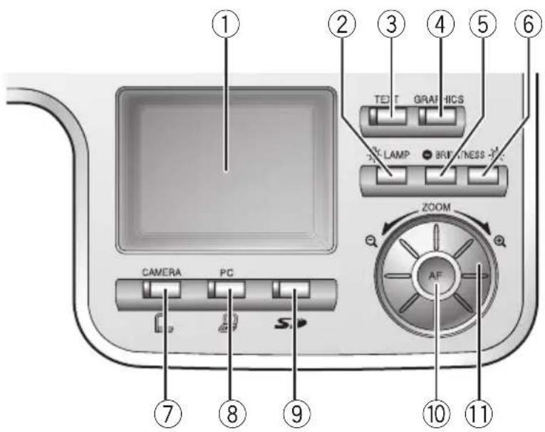
* Hereinafter the menu items to be displayed/selected on the monitor or projection screen are referred to as "OSD (On-Screen Display)".
| Name | Function | ||
| 1 | LCD panel To display the output image and the OSD | ||
| 2 |  LAMP To switch the illumination LAMP To switch the illumination | P.104 | |
| 3 | TEXT (Text mode) To switch the mode to Text1To make B&W images of letters or lines sharp in contrastUse this button to display materials such as documents | ||
| 4 | GRAPHICS (Color document) To switch the mode to GraphicsTo display color objects such as figures and photos | ||
| 5 | BRIGHTNESS(Brightness) | (Dark) | To darken the camera image P.110 |
| 6 | [YSXK] | (Light) | To lighten the camera image P.110 |
| 7 | CAMERA | To switch the output image to the camera image P.106 | |
| 8 | [SAAC] PC (RGB IN video) | To switch the output image to the RGB IN image P.106 | |
| 9 | (SD mode) | To switch the output image mode to the SD mode P.106 | |
| 10 | (Auto Focus) | To focus the camera automatically P.108 | |
| 11 | ZOOM To operate the zoom function by turning the dial | P.105 | |
ENGLISH
Rear Panel
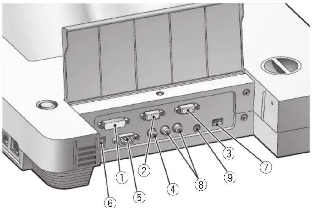
| Name | Function | Image whose display is selectable with image select button | |||
| 1 | DVI OUT(DVI Output Terminal) | To output digital video signal to the projector, the PC monitor or other DVI input device SD mod P.91 | Camera image | ||
| 2 | RGB OUT(Analog RGB PC Output Terminal) | To output analog video signal to the projector, the monitor or other RGB input device [RGB IN] in SD mode | Camera image | ||
| 3 | RGB IN Input image (Analog RGB terminal) (Input Terminal) | age is output from the analog RGB output (analog RGB terminal or the video out terminal when RGB IN is selected with image select button P.92 | |||
| 4 | VIDEO OUT(Composite Video Output Terminal) | To output image from the RCA pin-jack terminal to the NTSC/PAL-system monitor (e.g., TV monitor) P.92 | Camera image [RGB IN] image * SD mode | ||
| 5 | RS-232C To control (RS-232C Terminal) | rol the main unit from a PC through the RS-232C cable P.113 | |||
| 6 | 12VDC IN(Power Socket) | Socket for the AC adapter | |||
| 7 | DIP Switch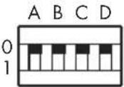 Display of Rear Panel Display of Rear Panel | To execute the following switching:[A] and [B] keys:Switch the resolution of the DVI and analog RGB output Settings [A] key [B] key SXGA 0 0 XGA 1 0 720p 0 1 (SXGA) 1 1 When switching the DIP switch key settings, be sure to turn OFF the power supply to the main unit. | |||
| AUDIO OUT(Audio Output Terminal) | To output the microphone input and the audio input in the mixed status P.102 | ||||
| 9 | AUDIO IN(Audio Input Terminal) | To output the input audio as it is from the AUDIO OUT terminal P.102 | |||
* [Video Out] → [Camera & SD] on the OSD skips [RGB IN] image.
■Side Panel

| Name | Function | |
| 1 | (USB terminal, compliant with 2.0) using | To enable the image transfer or the main unit control by the utility software on the supplied CD-ROM when the camera is connected to the PCP.91 |
| 2 | (SD Card Slot) To insertTo remove the SD card, push it | an SD cardin onceP.96 |
| 3 | Main Switch To turn ON/OFF the power supply | |
| 4 | (Ethernet terminal, 100BASE/10BASE) the camera | To enable the image transfer or the main unit control when is connected to the networkP.101.102 |
| 5 | MIC(Microphone input terminal) terminal microphone) is connected to the PC. The audio volume is adjustableP.101.102 | |

Explanation of the Ethernet terminal LED

OSD (On-Screen Display)
The menu items displayed/selected on the monitor or the projection screen are referred to as "OSD (On-Screen Display)".
When the [MENU] button on the wireless remote control is pressed, the OSD menu appears on the monitor screen. (When this [MENU] button is pressed again, the OSD menu disappears.)
Move to the item to be set by pressing the [▲▼◀▶] direction buttons on the wireless remote control, and press the [ENTER] button to fix the setting. When the [◀] direction button is pressed, the OSD menu hierarchy is traced back. When the same button is pressed on the first hierarchy, the OSD menu disappears.
Sample image of the top and 2nd hierarchies

■Camera Mode (Menu when camera image is in display)
| Function | Name | |||
| Top hierarchy | 2nd hierarchy | 3rd hierarchy | ||
| IP Address Display | To display the IP address | |||
| Brightness | Auto | √ | To vary the degree of brightness automatically according to the objectP.110 | |
| Manual | To fix the image brightness to any levelP.110 | |||
| Mode | Text3 | Text1, Text2 and Text3 are used to display B&W characters and documents sharply. The larger the number affixed to Text is, the larger the effect is.Graphics is used to display color figures and photographs cleanly. Only when Graphics is selected, Edge Effect and Gamma can be set. | ||
| Text2 | ||||
| Text1 | √ | |||
| Graphics | ||||
| White Balance | Auto | √ | To set the white balance to automatic following | |
| One-Push | To set the white balance to fix | |||
| Manual | To adjust the red intensity and the blue intensity manually | |||
| R-Gain | (Displayed in level bar form) | To adjust the red intensity when the white balance is set to manual | ||
| B-Gain | (Displayed in level bar form) | To adjust the blue intensity when the white balance is set to manual | ||
| Edge Effect | 3 | This can be set only when the mode is set to Graphics. Edge enhancement is provided to the image to make it sharp. The larger this number is, the larger the effect is | ||
| 2 | ||||
| 1 | √ | |||
| Off | ||||
| Gamma | High | To set the gamma curve when the mode is set to GraphicsThe grayscale can be varied as you like. | ||
| Normal | ||||
| Low | √ | |||
| USB Mode /Ethernet Setting change becomes effective when the power switch is turned OFF and then turned ON. | Mass Storage (Transfer) | Yes or No | Mode to be set to transfer the data from the SD card into the USB-connected PCP.100 | |
| Application | Yes or No | Mode to be set to control the main unit from the USB-connected PC or transfer the image into the USB-connected PCP.99 | ||
| Ethernet | Yes or No | Mode to be set to control the main unit from the Ethernet-connected PC or transfer the image into the Ethernet-connected PCP.101.102 | ||
| Function | Name | ||
| Top hierarchy | 2nd hierarchy | 3rd hierarchy | |
| Capture SDwhen the button on the wireless remote control is pressedEthernet Mode to save the image file in the FTP server when USBMode/Ethernet is set to Ethernet | Mode to write the image on the SD card set on the main unit side | ||
| Guide | On | √ | To set whether the operation status of the main unit should |
| Off | be displayed. | ||
| Video OutCamera & SD | All Mode | √ | To output the [VIDEO OUT] terminal signal according to all video switching |
| To (Image of Camera & SD only) | limit the switching of the [VIDEO OUT] terminal output to the camera video and the SD mode | ||
| Flickerless(Flicker compensation) | 60Hz | √ | To reducer fluorescent lamp flicker due to power supply frequency |
| 50Hz | |||
| Ethernet Status DefaultSetting change becomes effective when the power switch is turned OFF and then turned ON. | To reset the Ethernet Status to the factory settings | ||
| Call (Setting Call)USB Mode/Ethernet, Flickerless/WEB Ethernet settings | To reset the Call to the factory settings (not applicable to | ||
| Mic Volume | (Displayed in the level-bar form) | To adjust the audio level of the microphone input | |
* [✓] indicates the factory default settings. The factory default settings of Flickerless vary according to the destination. The settings of USB Mode and Flickerless retain the last set state.
Sample image of the 1st, 2nd and 3rd hierarchies

■ SD Mode (Menu when image stored in an SD card is in display)
| Name Function | |||
| Top hierarchy | 2nd hierarchy | 3rd hierarchy | |
| Delete P.98 | Current (Selected Image) | No | To cancel the delete |
| Yes | To delete the image in display on the full screen or the image selected from the split screen.Locked image can not be deleted. | ||
| All (All images) | No | To cancel the delete | |
| Yes | To delete all images | ||
| Lock | Current (Selected image) | image selected from | To lock the image in display on the full screen or the from the split screen.Can set the image not to be deleted or select image for slide-show.On the split screen, a green frame appears on the locked image. |
| All (All Images) | To lock all image files. Can select the delete-protected image or the image to be displayed on the slide show | ||
| Unlock (Lock Release) | Current (Selected Image) | To release the lock of the image in display on the full screen or the image selected from the split screen | |
| All (All Images) | To release the lock of all image files | ||
| Format Media P.98 | Format (Initialize) | No | To cancel the format |
| Yes | To format the SD cardAll data will be deleted from the card. | ||
ENGLISH
| Function | Name | |||
| Top hierarchy | 2nd hierarchy | 3rd hierarchy | ||
| Slide Interval Show (Interval of Image 5 Sec Settings P.98 d) | 3 Sec To set the 10 Sec | interval of slide show image from 3 to 3 | how until displaying the next 0 sec | |
| image from 3 to 3 | ||||
| 15 Sec | ||||
| 30 Sec | ||||
| Effect (Effect of Image Feed) | Left to right | To slide from left to right | ||
| LT to RB | To slide diagonally from left top to right bottom | |||
| RT to LB | To slide diagonally from right top to left bottom | |||
| None To show to | visual effect | |||
| Select (Object File) | All √an SD card | To set the slide-show objects to all displayable images in | ||
| Locked Only | To set the slide-show objects only to the locked image files | |||
| Order (Order of Image Feed) | Forward √the smallest to the | To give slide show in order of file name serial No. from largest | ||
| Backward the largest to the | To give slide show in order of file name serial No. from smallest | |||
| Repeat | Off √ | To set whether the slide show should be played repeatedly or not | ||
| On | ||||
| Start Slide Show | To start the slide show | P.98 | ||
| Display | Single | To set the number of the images in an SD card to be displayed on the split screen | ||
| 3×3 √ | ||||
| 4×4 | ||||
* [✓] indicates the factory settings.
Wireless Remote Control

| Name | Function | |||
| 1 | PRESET (State Save) To save the current setting state of the unit Use this function together with the memory No. | [WYCB] | ||
| 2 | CALL (State Call) To call the settling state Use this function together with the memory No. |  | ||
| 3 | (Memory No.) To indicate the memory No. | |||
| Name | Function | |||
| 4 | (OSD Operation) | MENU To display/ | cancel the OSD P.77 | |
| 5 | ENTER (Input) | To fix the OSD item P.77 | ||
| 6 | (Directions) | ▲▼◄►the digital zoom is used | To select the OSD item, and scroll the LCD monitor when P.77 | |
| 7 | ◄(Menu Cancel) resumed | To cancel the OSD from the screen when the top OSD item P.77 | ||
| 8 | POSI/NEGA To switch the posi/nega of the camera image | |||
| 9 | COLOR/B&W(Color/Black and White) | To switch the Color/Black and White of the camera image Use this function to make the black-and-white document easy-to-read | ||
| 10 | BRIGHT NESS(Brightness adjustment) | NORMAL | To return the automatic brightness adjustment level to the standard level P.110 | |
| 11 | ⊕(Bright) | To brighten the camera image P.110 | ||
| 12 | ⊖(Dark) | To darken the camera image P.110 | ||
| 13 | ZOOM(Wide-angle) | ⊕(Telescopic) | To zoom in P.105 | |
| 14 | ⊖(Telescopic) To zoom out | P.105 | ||
| 15 |  (Image Save)image. (Image Save)image. | To save the image on the SD card or FTP-transfer the | ||
| 16 |  (SD mode) (SD mode) | To switch the output image mode to the SD mode P.106 | ||
| 17 | [DZKB] (CAMERA) | To switch the output image to the camera image P.106 | ||
| 18 | [8ADT] (PC) | To switch the output image to the RGB IN image P.106 | ||
| 19 | GRAPHICS (Color documents) To display color objects, such as figures and photos | |||
| 20 | Text (Text Mode) | To switch the mode to Text1To sharpen the image with black-and-white characters and linesUse this function to shoot the document or the like | ||
| 21 | EDGE EFFECT(Edge Enhancement) The edge effect is applied to the image for sharpeningThis function | To switch the 1/2/3/OFF of the edge enhancement | ||
| 22 | PAUSE again, the moving image is restoredThe paused image cannot be processed in any other way. | |||
| 23 | IMAGE ROTATION (Image Turn) | To turn the camera image by 180° | ||
| 24 | FOCUS FAR | NEAR | To move the focus near P.108 | |
| 25 | To move the focus far | P.108 | ||
| 26 | AF (Auto Focus) | To focus the camera automatically P.108 | ||
| 27 |  (Lamp)illuminations (Lamp)illuminations | Each time this button is pressed, the material illumination lights up → the base illumination lights up → both go out in this order. P.104 | ||
■Receivable Range

Point the infrared emitting part of the wireless remote control at the infrared sensor of the main unit, and press the button for desired function.
The receiving range may be reduced when the main unit is placed in direct sunlight, near an inverter fluorescent lamp or in any other unfavorable surroundings.
Depending on the conditions of fluorescent lamps, etc., the sensor may fail to receive the infrared light. In such case, relocate the main unit, or take other countermeasures.
- Receivable range
Distance: Approx. 7m (23ft) or less from the front of the infrared sensor
Angle: Approx. 30^ or less to the rightward, leftward, upward and downward, respectively, from the infrared sensor

Battery Change
Remove the battery case cover on the rear side by pressing down the [OPEN] mark part in the direction as indicated by the arrow.
Install 2 batteries (Type R03, AAA) in the battery case in the direction as indicated.

Install the batteries with the correct polarity.

Although the battery life depends on the operating conditions and battery type, the batteries are recommended to be changed once a year.

The supplied batteries are only for use in initially confirming the operation of this product. Therefore, it is not guaranteed that these batteries remain alive for the validated period.
WEB Screen
When connection is made to http://192.168.0.100 on the browser, its top page opens. By clicking each item there, the clicked item can be operated.

"192.168.0.100" is default. Input the IP address used in the network configuration of SET UP.
■Top page

It is necessary to set USB Mode/Ethernet to Ethernet on the OSD, and use it in the camera mode.

If the resolution settings are changed with the DIP switch or the USB Mode/Ethernet settings are changed, restart the browser.

If USB Mode/Ethernet has been set to Mass Storage or Application on the OSD, SET UP alone will become effective.
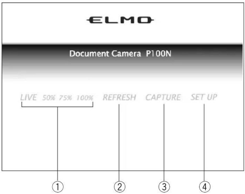
| Name | Function | |
| 1 | LIVE (Video image display) | To display the video image at 50%, 75% or 100% scaleP.84 |
| 2 | REFRESH To display the REFRESH page | P.84 |
| 3 | CAPTURE To display the still image | |
| 4 | SET UP (Ethernet setting) To display the configurations page | P.85 |
ENGLISH
LIVE

PART NAMES AND FUNCTIONS
| Name | Function | |
| 1 | CONTROL(WEB remote control) | To display the WEB remote control when this item is clickedP.88 |
■REFRESH

| Name | Function | |
| 1 | manual To display the [refresh] updating the still image | button without automatically |
| 2 | Interval To update the still image | at each time intervals |
| 3 | refresh To update the still image (applicable only in the manual mode) | when this item is clicked |
| 4 | CAPTURE To display the still image is clicked | image in another window when this item |
| 5 | TOP To display the top page |

When the [PAUSE] button on the wireless remote control is pressed in the SD mode, the video image and the still image cannot be displayed.
■CONFIGURATIONS
CONFIGURATIONS
Network Configuration
| IP address | 192.168.0.100 |
| Subnet mask | 255.255.255.0 |
| Default gateway | 0.0.0.0 |
| Root Password | |
| User Password |
FTP Client Configuration
| The IP address of the image receiving server | 0.0.0.0 |
| The port number of the image receiving server | 21 |
| User account for the image receiving server | anonymous |
| Password for the image receiving server | |
| Passive Mode | on |
| Destination directory to save | / |
| The name of image file | ime |
| Add the sequence number to file name? | no |
| The start number of sequence | 0 |
| The end number of sequence | 999 |
TOP 5
| Name | Function | |
| 1 | Network Configuration To display the network configuration page | P.86 |
| 2 | — Configuration of the current network | |
| 3 | FTP Client Configuration To display the FTP client configuration page | P.87 |
| 4 | — Configuration of the current FTP client | |
| 5 | TOP To display the top page |
■ Network Configuration
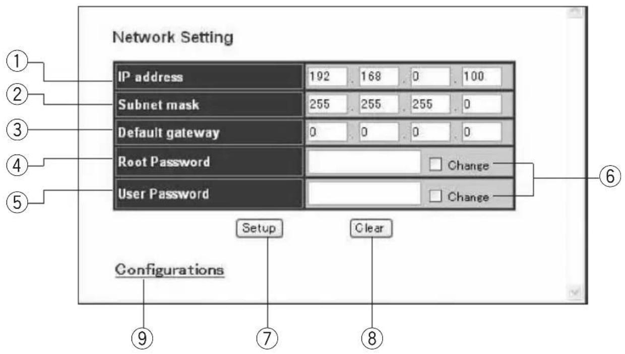
| Name | Function (<>: Factor | |
| 1 | IP address IP address information set in this camera system<192.168.0.100> | |
| 2 | Subnet mask <255.255.255.0> | |
| 3 | Default gateway Router IP address<0.0.0.0> | |
| 4 | Root password Password for setting the network, using the FTP server function, setting of the FTP client and using the telnet.Up to 127 alphanumeric characters | |
| 5 | User password Password for setting the FTP client to enable the use of the[image transfer] button and using the FTP server function.Up to 127 alphanumeric characters | |
| 6 | □Change checked. If this check box is checked but nothing is entered in the password edit box, the relevant password information will be cleared. | To set or change the password, this check box should be checked but nothing is entered in the password edit box, the relevant password information will be cleared. |
| 7 | Setup | To set to the contents in display |
| 8 | Clear page | To reset all edit contents to the state as of opening of this |
| 9 | Configurations | To display the configurations page |

Network configuration change becomes effective when the power switch is turned OFF and then turned ON.
ENGLISH
■FTP Client Configuration
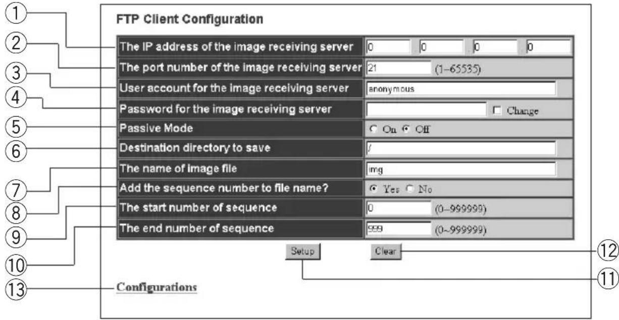
| Name | Function | |
| 1 | The IP address of the image receiving server <0.0.0.0> as of shipment from our factory | To designate the IP address of the saving destination FTP server |
| 2 | The port number of the image To designate the port No. of the FTP server running in the receiving server saving destination host<21> as of shipment from our factory | To designate the account name necessary for connection to the receiving server saving destination host.as of shipment from our factory |
| 3 | User account for the image receiving server saving destination host.as of shipment from our factoryUp to 127 alphanumeric characters including hyphen (-) and underscore (_ ) | To designate the account name necessary for connection to the |
| 4 | Password for the image receiving To designate the password of the above account server No setting as of shipment from our factoryUp to 127 alphanumeric characters | To designate the password of the above account |
| 5 | Passive Mode mode or active modeNo use as of shipment from our factory | To designate which mode should be used for file transfer, passive |
| 6 | Destination directory to saveAs of shipment from our factoryUp to 255 alphanumeric characters including hyphen (-), underscore (_ ) and slash (/) | To designate the image file saving directory |
| 7 | The name of image fileTo designate the name of the saving file The file name is affixed automatically with the [.jpg] extension.as of shipment from our factoryUp to 255 alphanumeric characters including hyphen (-) and underscore (_ ) | To designate the name of the saving file with the [.jpg] extension. |
| 8 | Add the sequence number to file name?To designate whether sequence No. should be added to the file name or not: [Yes]/[No]as of shipment from our factory | To designate whether sequence No. should be added to the file name or not: [Yes]/[No] |
| 9 | The start number of sequence with sequence No. | To designate the sequence start No. when the file name is added |
| <0> as of shipment from our factory | ||
| 10 | The end number of sequence with sequence No. | To designate the sequence end No. when the file name is added |
| If there is any file name added with the same No., such file will be overwritten. Therefore, it is advisable to designate the sequence end No. on the larger side. | ||
| <999> as of shipment from our factory | ||
| 11 | Setup | To set to the contents in display |
| 12 | Clear | To reset all edit contents to the state as of opening of this page |
| 13 | Configurations | To display the configurations page |
■WEB remote control

| Name Function (One-click operation) | |||
| 1 | ZOOM TELE To | zoom in | |
| 2 | WIDE To zoom | out | |
| 3 | LAMP Each time this button is | pressed, the material illumination lights up → the base illumination lights up → both illuminations go out in this order. | |
| 4 | BRIGHTNESS standard | NORMAL level | To return the automatic brightness adjustment level to the |
| 5 | OPEN To brighten the camera image | ||
| 6 | CLOSE To darken the camera image | ||
| 7 | FOCUS | NEAR | To move the focus near |
| 8 | FAR To move the focus far | ||
| 9 | AF To focus the camera automatically | ||
| 10 | GRAPHICS To switch the mode to Graphics | ||
| 11 | TEXT To switch the mode to Text1 | ||
| 12 | EDGE EFFECT To switch the 1/2/3/OFF of the edge enhancementEffective only in the Graphics mode | ||
| 13 | IMAGE ROTATION | To turn the camera image by 180° | |
| 14 | POSI/NEGA To switch the posi/nega of the camera image | ||
| 15 | COLOR/B&W | To switch the color/B&W of the camera image | |
2 SETTING UP
Setting Up
(1) Release the camera column lock by turning the security lock knob.

(2) As shown in the right figure, hold the setup grip and raise the camera column. At this time, the camera head slides up in conjunction with the rise of the camera column. The lamp column also rises together.

natural_image
Diagram showing a device being processed from a base to a device with a curved arrow indicating motion (no text or symbols present)
(3) If necessary, move the lamp column and the lamp head to an appropriate position as shown in the right figure.

When using a glossy paper, the document could reflect the illumination to disable normal display. In this case, adjust the lamp position to a position in which such reflection can be avoided.


If the camera column is pulled or pushed forcedly, the camera might be pushed out of position by a function not to break mechanical parts, and the camera image might be displaced from the display center. In this case, initialize the camera position as follows:
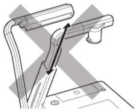
natural_image
Technical line drawing of a mechanical assembly with no visible text or symbols(1) Fold the camera column on the stage. When the camera column is folded in the storage position, the camera position is initialized.

(2) Then, raise the camera column.

Connecting Cables
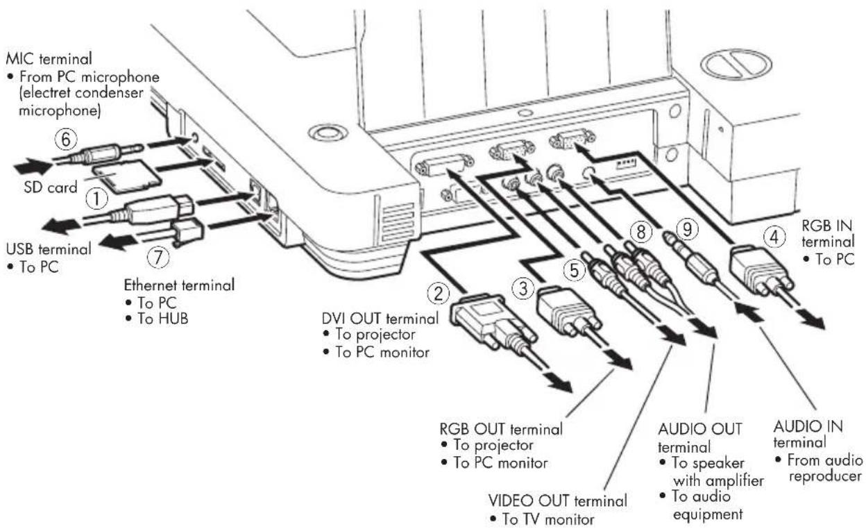
To protect this product and the peripheral units to be connected to this product, be sure to turn OFF the power supply to all units beforehand.
When plugging in/out the connection cable, hold the plug part of the cable.
For the information of image output switching, refer to P.75 (DIP Switch).
Load the SD card with the label facing up. Forcible insertion by mistake could cause failure.
This camera system does not accept the SDHC card. Use the recommended card only.
①Connecting to the PC with a USB cable
Connect the USB cable to the [ ] (USB) terminal on the side panel.
The USB cable compliant with USB2.0 is recommended.
If you plug into a USB cable with power on, PC may not recognize this product.
Depending on the USB environment used by the PC or the influence of peripheral units, the video transfer could be disturbed.
This does not guarantee the normal operation in any environment.
②Connecting to the unit having the DVI input terminal
Connect the DVI cable to the [DVI OUT] terminal on the rear panel.
③Connecting to the unit having the analog RGB input terminal
Connect the analog RGB cable to the [RGB OUT] terminal on the rear panel.

The display position may be displaced from the center of the screen. In such case, adjust the horizontal and vertical positions manually from the connected device.

Vertical stripes may appear on the LCD projector screen or the monitor screen. This phenomenon can be mitigated by adjusting the dot clock manually from the connected device.
④Connecting to the unit having the analog RGB output terminal
Connect the analog RGB cable to the [RGB IN] terminal on the rear panel.
- Specifications of the analog RGB input terminal of this product
Signal allocation

DSUB 15P shrink terminal (Female)
Video signal : Analog 0.7V(p-p) 75Ω terminated
Horizontal synchronized signal : TTL level (Positive/negative polarity)
Vertical synchronized signal : TTL level (Positive/negative polarity)
Pin assignment
| Pin No. | Name | Pin No. | Name | Pin No. | Name |
| 1 | Video signal (Red) | 6 | GND (Red) | 11 | GND |
| 2 | Video signal (Green) | 7 | GND (Green) | 12 | N.C |
| 3 | Video signal (Blue) | 8 | GND (Blue) | 13 | Horizontal synchronized signal |
| 4 | N.C | 9 | N.C | 14 | Vertical synchronized signal |
| 5 | GND | 10 | GND | 15 | N.C |
⑤Connecting to the unit having the composite video input terminal
Connect the video cable with RCA pin plug to the [VIDEO OUT] terminal on the rear panel.
⑥Connecting to the microphone
Connect the microphone for PCs (electret condenser microphone) equipped with 3.5mm mini plug cord to the [MIC] terminal on the side panel.
⑦Connecting to the PC and the network with the Ethernet cable
Connect the Ethernet cable to the [ ] (Ethernet) terminal on the side panel.
⑧Connecting to the speaker
Connect the speaker equipped with amplifier and RCA pin plug cord to the [AUDIO OUT] terminal on the rear panel.
⑨Connecting to the audio reproducer
Connect the audio cable equipped with 3.5mm mini plug to the [AUDIO IN] terminal on the rear panel.
3 STORING
Storing
(1) Return the lamp to the original position. Then, hold the setup grip of the camera column and fold the camera column. At this time, the camera head slides down and the lamp column also folds.

Turn OFF the power switch before the storing.

(2) Lock the camera column and the lamp column by turning the security lock.


Do not force down the camera column and the lamp column when folding them.

Do not fold the camera column when the close-up lens holder remains open, or the close-up lens could be damaged.

natural_image
Technical line drawing of a mechanical assembly with no visible text or symbols
When this camera system is not in use, unplug the power cord and the AC adapter from the plug socket.

Close-up lens holder
Turning ON/OFF the Power Supply

Be sure to use the main switch on the main unit to turn ON/OFF the power supply to the main unit.

Do not turn ON/OFF the power supply by plugging/unplugging the AC adapter or the power plug.

When connecting to other units, turn OFF the power supply to all connecting units.
It takes the main unit about 30 seconds to be ready for operation. During this time, the logo is on display.

It takes the main unit about 10 seconds to be shut down completely. During this time, the logo is on display.


Connection of the AC adapter
Plug the DC plug of the attached AC adapter into the [12VDC IN] terminal on the rear panel, and then plug the AC adapter into the plug socket.

About power failure
Even if it is momentary, power failure would turn OFF the power supply to the main unit. In case of power failure, manually turn ON the power supply to the main unit after power recovery. If power failure is probable, it is advisable to install a UPS (uninterruptible power supply system).
Presentation by Using Documents, Films, etc.

natural_image
Line drawing of a portable electronic device connected to a projector via cable (no text or symbols)①Setting the main unit
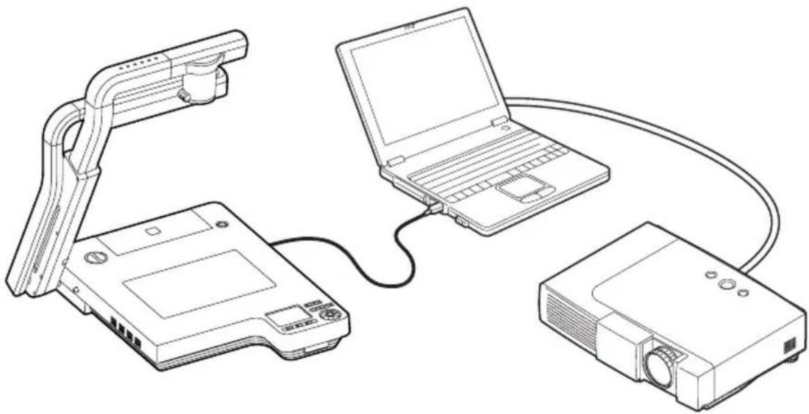
Set the main unit as show in the above figure, connect the main unit to the projector or the PC monitor, and then turn ON the power supply.
②Adjusting the size
Place an object on the stage, and adjust the position of the object with the zoom dial [ZOOM] on the front operating panel or the zoom button ([ ⊕ ], [ ⊖ ]) on the wireless remote control so that the part of the object to be viewed can fit the screen size.
③Adjusting the focus
Press the [AF] button on the front operating panel or wireless remote control to focus the camera on the object.
④Adjusting the brightness
Press the [BRIGHTNESS • ⚙️] button on the front operating panel or wireless remote control to adjust the brightness of the image by the lens iris.
When the illumination is switched by pressing the [LAMP] button, the light distribution according to the material can be achieved.

When the main unit is connected to the DLP projector and GRAPHICS is selected, both documents and photos may be projected sharply. If necessary according to the projected condition, select GRAPHICS.
P.77
Presentation using optional SD card (Option)


Before starting the operation, insert an optional SD card (Option) into the SD card slot on the side panel. Push it again to remove the SD card.

When loading/unloading the SD card or the power supply is turned off, be sure to select the camera image by pressing the [ ] button on the front operation panel or wireless remote control and confirm that the output image has been turned to the camera image beforehand. Otherwise, the SD card contents could be broken or failure could be caused to this camera system.

The SD card is composed of parts vulnerable to static electricity. Therefore, due to the impact of static electricity, the SD card could malfunction or its contents could be destroyed. When handling the SD card, take care to avoid static electricity.

The image data viewable on this camera system is limited to the image data saved in this camera system and the image data converted on the dedicated conversion software attached to this camera system.

If the data of the system that is not compatible with this product, a black or gray image will be displayed.

If the camera conversion to the image on the SD card is tried without loading the SD card, the output screen will be blackened. ([NO CARD] will be displayed on the screen.)

After using the SD card, do not leave it inside this product but be sure to remove it.

As an SD card, Panasonic 256MB or 512MB is recommended.
The resolutions of the image to be stored are 1280 × 1024 (SXGA output), 1280 × 720 (HDTV output) and 1280 × 960 (XGA output).
This product can store images up to 2048 pcs.

ELMO is not liable for any damage caused by the loss of the data in the SD card or passive damage.

The dedicated conversion software attached to this camera system cannot be used in the SD mode. Also, do not switch the mode to the SD mode during when the dedicated conversion software is in use, or failure could be caused to this camera system.
Presentation using optional SD card (Option) (Continued)
■Saving the Image
(1) Press the [ ] button on the front operating panel or wireless remote control to switch the image mode to the Camera mode.
(2) Press the [图标] button on the wireless remote control.
(3) When the [图标] mark lights up on the screen, the image saving starts. When this mark goes out, the image saving is completed.

Set [Capture] to [SD] on the OSD

Be sure to try shooting and confirm the normal saving of the image beforehand. If the image should be unable to be saved normally due to some problem with this camera or the SD card, we are not liable to compensate for such failure.

The [图标] mark on the screen is displayed only when the [Guide] menu is set to ON.

When the SD card is write-protected, the image cannot be saved in the SD card.

When the capacity of the SD card becomes full and no more images can be saved, the [☐] mark does not light up. Then, delete unnecessary images or use a new SD card.

When the SD card is in the read/write mode, do not remove the SD card, or failure could occur with this product.

If the image saving is tried when the digital zoom is in operation, the digital zoom will be cancelled and the image will be saved at the magnification set as of the shipment.

The image file does not record the correct time and date.
■Displaying the image
(1) When the [SD] button on the operating wireless remote control is pressed to switch the mode to the SD mode, the images saved on the SD card are displayed on the split-screen. The number of divisions can be changed by changing the OSD [Display] setting, which is 3×3 by default.

3 × 3
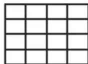
4× 4
(2) Move the selection frame (cursor) of the recorded image to the desired image by using the direction buttons [▲▼◀▶] on the wireless remote control, and press the [ENTER] button on the wireless remote control to display the selected image on the full-screen.
- When the images are displayed on the split screen (3×3, 4×4)
Move the selection frame (cursor) of the recorded image to the desired image by using the direction buttons [▲▼◀▶] on the wireless remote control, and press the [ENTER] button on the wireless remote control to display the selected image on the full-screen. When the direction button [▼] is held down, the selection frame (cursor) keeps downward movement as shown in the right figure.
- When the images are displayed on the full-screen. When the direction button [▶] or [▼] on the wireless remote control is pressed, the next image is displayed. When the direction button
[◀] or [▲] is pressed, the previous image is displayed again.
The image displayed on the full-screen can be zoomed in/out by using the zoom dial on the front operating panel or the zoom button on the wireless remote control. When the image is zoomed in, the displayed part of the image can be scrolled by using the direction buttons [▲▼◄►].

■Deleting the Image
(1) Press the [SD] button on the front operating panel or wireless remote control to display the images stored in the SD card in the full screen display mode or the divided screen display mode.
(2) Select the image to be deleted by using the direction buttons [▲▼◀▶] on the wireless remote control.
(3) Press the [MENU] button on the wireless remote control, and select the [Delete] menu of the OSD. To delete only the selected image, select [Current]. To delete all images, select [All].
When [Yes] is selected by pressing the [ENTER] button on the wireless remote control, the deletion is executed. (To cancel the deletion, select [No].)
■Slide show
(1) Press the [SD] button on the front operating panel or wireless remote control, and switch the output image mode to the SD mode.
(2) Display the OSD by pressing the [MENU] button on the wireless remote control. When the [START SLIDE SHOW] menu is selected, the slide show starts.
(3) When one of the direction buttons or the [ENTER] button on the wireless remote control is pressed, the slide show stops.
- [Effect] (visual effect), [Interval] (display interval) and [Repeat] (repetition) can be set from the [Slide Show Settings] menu of the OSD.
■Formatting the SD card
When the SD card is formatted, insert the SD card into this product, and execute formatting.
(1) Press the [SD] button on the front operating panel or wireless remote control, and switch the output image mode to the SD mode.
(2) Display the OSD by pressing the [MENU] button on the wireless remote control, and select [Format Media].
(3) When [Yes] is selected by pressing the [ENTER] button on the wireless remote control, the deletion is executed. (To cancel the deletion, select [No].)
Now, [format] starts.

All data on the SD card is deleted.
Presentation using the supplied software with the USB-connected PC
natural_image
Line drawing of three electronic devices connected by a cable, including a laptop, a projector, and a handheld device (no text or symbols present)
Set [USB Mode/Ethernet] to [Application] on the OSD.
"Utility Software" is available from the supplied CD-ROM supplied from us.
"Utility Software" contains PC link software "Image Mate for Presentation" and TWAIN driver "ELMO TWAIN DS" (VHN) to allow the following operation:
- Transfer of moving/still images to the PC
• Operation of this product from the PC
A PC that Microsoft Windows2000 (SP4 or newer) or XP (SP2 or newer) has been installed is recommended.
For details, refer to the "Utility Software" Installation Manual and the help folder with the software.

When the power supply to this camera system is ON, do not connect/disconnect the USB cable, or malfunction will be caused to this camera system.

The USB cable compliant with USB2.0 is recommended.

When this camera is connected with the PC with a USB cable, the camera image frame rate lowers.

Depending on the USB environment used by the PC or the influence of peripheral units, the video transfer could be disturbed.

This does not guarantee the normal operation in any environment.
Transferring the images from the SD card into the USB-connected PC
natural_image
Line drawing of an electronic device connected to a laptop via cable, showing internal components (no text or symbols)
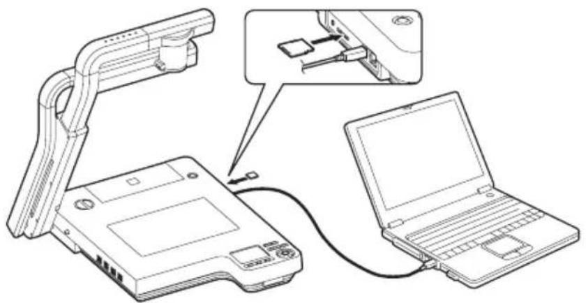
Set [USB Mode/Ethernet] to [Mass Storage] on the OSD.
When this product is USB-connected to the PC, image data in the SD card can be transferred into the PC. The connectable PC is one that has been installed with Microsoft OS Windows2000 (SP4 or newer) / XP (SP2 or newer) / Vista.
(1) Turn ON the power supply to this product and to the PC.
(2) Connect this product to the PC with the supplied USB cable.

When this product is connected to the PC for the first time, the required drivers are installed automatically due to the plug-and-play function of Windows. For the second time and thereafter, the drivers are no longer installed.
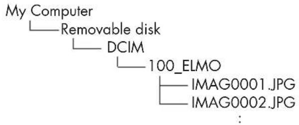
(3) This product is recognized as a removable disk. The image data in an SD card can be viewed by using the viewer software of the PC.
- The image data are stored in JPEG format in the following folders:

An SD card set in this product cannot be formatted or written, deleted, locked, and unlocked with image data from the PC.

The image data cannot be recorded with the correct date and time.

When the power supply to this camera system is ON, do not connect/disconnect the USB cable, or malfunction will be caused to this camera system.

Do not switch [USB Mode/Ethernet] when this camera system is in USB connection.

The USB cable compliant with USB2.0 is recommended.

When this camera is connected with the PC with a USB cable, the camera image frame rate lowers.

Depending on the USB environment used by the PC or the influence of peripheral units, the video transfer could be disturbed.

This does not guarantee the normal operation in any environment.
Displaying the Video Image through Network Connection

natural_image
Line drawing of a laptop connected to an open electronic device via cable (no text or symbols)
Set [USB Mode/Ethernet] to [Ethernet] on the OSD.
When connection is made to http://192.168.0.100 on the browser, its top page opens. When [50%], [75%] or [100%] of [Live] is clicked, the video image is displayed. When [REFRESH] or [CAPTURE] is clicked, the still image is displayed.

To enable the access to this camera system on the web browser, the PC environment should be as follows:
- Windows2000 (SP4 or newer) / XP (SP2 or newer) / Vista has been installed.
- JRE (Java Runtime Environment) 1.5.0_12 or newer has been installed, and Java (Sun) is valid.
- Internet Explorer6 or 7 has been installed.

This camera system does not guarantee the normal access operation on all web browsers.

Depending on the version of the OS, the window size could not be set properly and/or the scroll bar could be displayed.

Depending on the settings of the Windows or virus check software, unfavorable phenomena, such as impossible connection to the camera and disturbed video image display, could occur. In this case, adjust the settings properly following the instruction manual of Windows or the virus check software.

This camera system uses the port of HTTP:80, FTP:20,21, telnet:23. When this camera system is connected to a router, firewall, etc., set the ports of these equipment accordingly.

In the SD mode or when the [PAUSE] button is pressed on the wireless remote control, neither the video image nor the still image can be displayed.

This camera system can be remote-controlled or the status of this camera system can be captured by using the telnet. For the information of its command, etc., contact the sales outlet from which you have purchased this camera system or the nearest branch office or sales office of ours.

The browser address "http://192.168.0.100" is in default setting. Input the IP address to be used for the network configuration of [SET UP].

When the resolution settings are renewed with the DIP switch or the settings of [USB Mode/Ethernet] are changed on the OSD, restart the browser.
Capturing the Image through Network Connection with the FTP
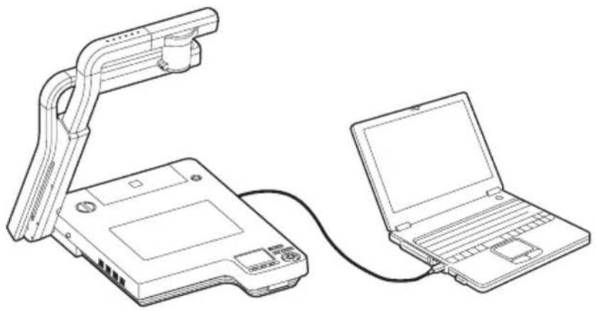
natural_image
Line drawing of an electronic device connected to a laptop via cable (no text or symbols)
Set [USB Model/Ethernet] to [Ethernet] on the OSD.

Set [Capture] to [Ethernet] on the OSD. (FTP client function)
The following 2 functions are available:
- FTP client function — Saving the image file in the FTP server by pressing the [图标] button on the wireless remote control
- FTP server function — Capturing the image to the PC through the FTP connection

The time and date of the file displayed on the FTP server are not correct.

This camera system does not guarantee all normal operations through the FTP connection.

This camera system uses the port of HTTP:80, FTP:20,21, telnet:23. When this camera system is connected to a router, firewall, etc., set the ports of these equipment accordingly.
Using [MIC IN] and [AUDIO IN]
![Elmo P100N - Using [MIC IN] and [AUDIO IN] - 1](/content/2026/05/957650/images/f6ae5d7ea12c45c01aac103f95363a0f840157163c1d658cbc8f0f482ca75462.jpg)
natural_image
Line drawing of a portable electronic device connected to a control panel and two microphones (no text or symbols)The microphone input and the audio input are mixed and output from [AUDIO OUT]. The microphone input level alone can be adjusted on the OSD.
![Elmo P100N - Using [MIC IN] and [AUDIO IN] - 2](/content/2026/05/957650/images/4cb6717da916122d0ddc21ca5778ab81bb0979ea049806cabbb5c9e801e833f4.jpg)
Only the microphone for PCs (electret condenser microphone) can be connected to [MIC IN]. If a microphone other than that for PCs is connected to [MIC IN], this camera system could be broken down. Before connection, carefully check the specifications of the microphone.
Shooting off the stage

natural_image
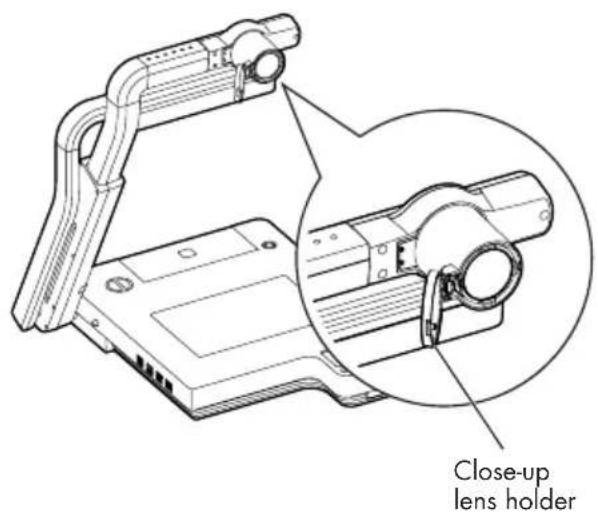
Technical line drawing of a mechanical clamp or clamp device with an inset close-up showing magnified views of the components (no text or symbols present)When the camera head is set in the horizontal direction, walls, distant views, etc. can be shot. When the object is distant, open the close-up lens holder.

Do not fold the camera column when the close-up lens holder remains open, or the close-up lens could be damaged.


When the camera head is set horizontally for shooting ahead of this camera, the image can be rotated automatically by 180^ .

Shooting area when the close-up lens holder is opened: TELE (Telescopic): 500mm - ∞ from the zoom lens WIDE (Wide-angle): 100mm - ∞ from the zoom lens
5 VARIOUS FUNCTIONS AND OPERATIONS
Lighting
Front operating panel
Wireless remote control

WEB remote control

This camera is equipped with material illumination for presenting materials, such as printed matter, and base illumination for transparent materials, such as slide films and negative films.
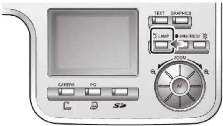
When the [LAMP] button on the front operating panel or wireless remote control is pressed, the fluorescent lamp lights up in 1 – 3 seconds.
• Each time the [●LAMP] button is pressed, the material illumination lights up →the base illumination lights up →both illuminations go out in this order.
Wireless remote control

WEB remote control


Both the material illumination and the base illumination cannot be extinguished together.

The illumination lamp helps obtain sharp display with good color rendering when it is used for a material surface with low brightness or for a three-dimensional object.

Do not look into the lamp unit of the material illumination. Also, do not touch the lamp unit of the material illumination when it is lighting, since it could be very hot.
Zoom
Front operating panel

Wireless remote control
natural_image
Front view of a remote control with black buttons and indicator lights (no text or symbols visible)WEB remote control

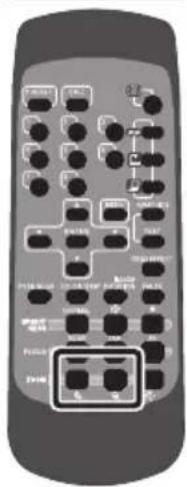
When the zoom dial [ ,⊕] on the front operating panel is turned or the zoom button [ ,⊕] on the wireless remote control is pressed, the document display range can be adjusted.
According to the zoom dial turning angle, the zooming speed varies in 3 steps (3-step speed change).
●Zoom magnification in the Camera mode
When the optical zoom is maximized (about 16×), the digital zoom is activated and the image can be zoomed in further up to 4× (about 64× combined with the optical zoom).
Front operating panel


Within the digital zoom range, the image quality is degraded.

Within the digital zoom range, the zoom speed is locked.

When the digital zoom is use, the LCD monitor can be scrolled by using the direction button [▲▼◄►] the wireless remote control.

During the video image transfer through the USB connection or during the image transfer through the Ethernet connection, the digital zoom slows down.

When the zoom button on the WEB remote control is clicked once, the zoom operates at regular intervals.

When the image is in transmission through the USB cable, the digital zoom speed get slow.

The digital zoom does not operate through the zoom via the WEB remote control.

If the zoom via the WEB remote control is tried when the digital zoom is in operation, the digital zoom will be cancelled and the maximum zoom-in position of the optical zoom will be resumed.
Wireless remote control

WEB remote control

flowchart
graph LR
    A["+"] --> B["←"]
    C["-"] --> D["←"]
    E["LAMP"] --> F["+"]
    G["Sun"] --> H["→"]
Image Selection
Front operating panel

Wireless remote control
natural_image
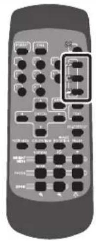
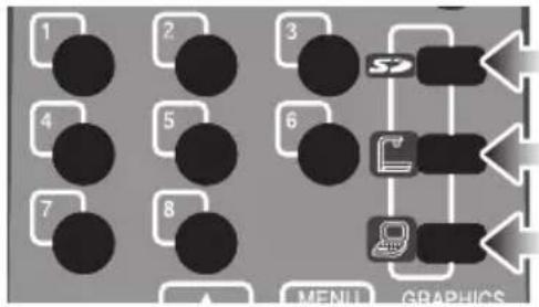
Close-up of a remote control with black buttons and a highlighted section (no text or symbols visible)Each time the [ ] , [ ] button and [ ] button on the front operating panel or wireless remote control are pressed, the image is switched among the camera image, the image inputted in the analog RGB input terminal [RGB IN] and the image stored in the SD card.
When the PC or other unit is connected to the analog RGB input terminal [RGB IN], the output image can be switched without spending time and labor exchanging the connection cables.
Wireless remote control
flowchart
graph TD
    1 --> 2
    2 --> 3
    3 --> 4
    4 --> 5
    5 --> 6
    6 --> 7
    7 --> 8
    8 --> 9
    9 --> 10
    10 --> 11
    11 --> 12
    12 --> 13
    13 --> 14
    14 --> 15
    15 --> 16
    16 --> 17
    17 --> 18
    18 --> 19
    19 --> 20
    20 --> 21
    21 --> 22
    22 --> 23
    23 --> 24
    24 --> 25
    25 --> 26
    26 --> 27
    27 --> 28
    28 --> 29
    29 --> 30
    30 --> 31
    31 --> 32
    32 --> 33
    33 --> 34
    34 --> 35
    35 --> 36
    36 --> 37
    37 --> 38
    38 --> 39
    39 --> 40
    40 --> 41
    41 --> 42
    42 --> 43
    43 --> 44
    44 --> 45
    45 --> 46
    46 --> 47
    47 --> 48
    48 --> 49
    49 --> 50
    50 --> 51
    51 --> 52
    52 --> 53
    53 --> 54
    54 --> 55
    55 --> 56
    56 --> 57
    57 --> 58
    58 --> 59
    59 --> 60
    60 --> 61
    61 --> 62
    62 --> 63
    63 --> 64
    64 --> 65
    65 --> 66
    66 --> 67
    67 --> 68
    68 --> 69
    69 --> 70
    70 --> 71
    71 --> 72
    72 --> 73
    73 --> 74
    74 --> 75
    75 --> 76
    76 --> 77
    77 --> 78
    78 --> 79
    79 --> 80
    80 --> MENSU & GRAPHICS

The image from the DVI output terminal [DVI OUT] cannot be switched to [RGB IN] image. P.75


The display mode of the image from the video output terminal [VIDEO OUT] cannot be switched when [Video Out] is set to [Camera & SD] on the OSD.

If the image mode switching is tried to the SD mode when an SD card is not in this product, the screen will turn black.

By setting [Guide] to [On] on the OSD, the setting contents are displayed on the screen.

To use a notebook-sized PC provided with the external output mode selective function, press the [ ] button on the front operation panel or wireless remote control, and then set the notebook-sized PC side to the external output mode.

If the [PAUSE] button on the wireless remote control is pressed in the SD mode, neither the video image nor the still image can be displayed on the WEB screen.
■ Input image signal that can be output from the video output terminal [VIDEO OUT] into the analog RGB input terminal [RGB IN]
| Signal Frequency Resolution | (Number of lines) | Polarity of synchronized signal(P: Positive, N: Negative) | ||||
| Mode name | kHz Hz MHz | Horizontal Vertical HS/VS | ||||
| VGA1 | 37.861 | 84.889 31.500 | 640 | 350 | P / N | |
| VGA2 | 37.861 85.080 | 31.500 | 640 | 400 | N / P | |
| VGA3 | 37.927 | 85.039 | 35.500 | 720 | 400 | N / P |
| VGA@60Hz | 31.469 | 59.941 | 25.175 | 640 | 480 | N / N |
| VGA@72Hz | 37.861 | 72.809 | 31.500 | 640 | 480 | N / N |
| VGA@75Hz | 37.500 | 75.000 | 31.500 | 640 | 480 | N / N |
| VGA@85Hz | 43.269 | 85.008 | 36.000 | 640 | 480 | N / N |
| SVGA@56Hz | 35.156 | 56.250 | 36.000 | 800 | 600 | P / P |
| SVGA@60Hz | 37.879 | 60.317 | 40.000 | 800 | 600 | P / P |
| SVGA@72Hz | 48.077 | 72.188 | 50.000 | 800 | 600 | P / P |
| SVGA@75Hz | 46.875 | 75.000 | 49.500 | 800 | 600 | P / P |
| SVGA@85Hz | 53.674 | 85.061 | 56.250 | 800 | 600 | P / P |
| XGA@60Hz | 48.363 | 60.004 | 65.000 | 1024 | 768 | N / N |
| XGA@70Hz | 56.476 | 70.069 | 75.000 | 1024 | 768 | N / N |
| XGA@75Hz | 60.023 | 75.029 | 78.750 | 1024 | 768 | P / P |
| XGA@85Hz | 68.677 | 84.997 | 94.500 | 1024 | 768 | P / P |
| SXGA1 | 67.500 | 75.000 | 108.000 | 1152 | 864 | P / P |
| SXGA2 | 60.000 | 60.000 | 108.000 | 1280 | 960 | P / P |
| SXGA3 | 85.938 | 85.003 | 148.500 | 1280 | 960 | P / P |
| SXGA@60Hz | 63.981 | 60.020 | 108.000 | 1280 | 1024 | P / P |
| SXGA@75Hz | 79.976 | 75.025 | 135.000 | 1280 | 1024 | P / P |
| SXGA@85Hz | 91.146 | 85.024 | 157.500 | 1280 | 1024 | P / P |
| UXGA@60Hz | 75.000 | 60.000 | 162.000 | 1600 | 1200 | P / P |
| UXGA@65Hz | 81.250 | 65.000 | 175.500 | 1600 | 1200 | P / P |
| UXGA@70Hz | 87.500 | 70.000 | 189.000 | 1600 | 1200 | P / P |
| UXGA@75Hz | 93.750 | 75.000 | 202.500 | 1600 | 1200 | P / P |
| UXGA@85Hz | 106.250 | 85.000 | 229.500 | 1600 | 1200 | P / P |
| Mac 13 | 35.000 | 66.667 | 30.240 | 640 | 480 | N / N |
| Mac 16 | 49.725 | 74.550 | 57.283 | 832 | 624 | N / N |
| Mac 19 | 60.241 | 74.927 | 80.000 | 1024 | 768 | N / N |
| Mac 21 | 68.681 | 75.062 | 100.000 | 1152 | 870 | N / N |
| PC98 | 24.825 | 56.420 | 21.052 | 640 | 400 | N / N |

This product may not accommodate any signal other than those listed in the above table.

Depending on the input signal, the image may not be outputted in full size.

This product does not accommodate such synchronized signal as composite and SyncOnGreen.
Focus
Front operating panel

Wireless remote control

natural_image
Front view of a remote control with multiple ports and buttons (no visible text or labels)WEB remote control

The focus on the object is adjusted.
■Auto Focus
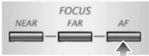
When the [AF] button on the front operating panel or wireless remote control is pressed, the camera is focused automatically. This product is of one-shot auto focus type. That is, once the camera is focused, the auto focus operation is released, and then focus position is maintained.

The objects listed below may not be brought into focus in the auto focus. In such case, use the manual focus mode.
- Objects having little contrast
- Objects with fine repeated patterns, such as lateral stripes and cross stripes
- Objects glittering or reflecting strong light
- Objects with bright background or excessive contrast
- Objects that are entirely dark
- Objects located near and far away at the same time
- Objects in motion

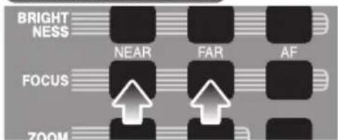
If the manual focus button [FOCUS • NEAR] or [FOCUS • FAR] on the wireless remote control is pressed when the auto focus is in operation, the auto focus operation will be cancelled.
Wireless remote control

WEB remote control
AND OPERATIONS
FUNCTIONS
VARIOUS
Wireless remote control
WEB remote control

ENGLISH

Limit of focus adjustment:
- With close-up lens TELE (Telescopic) : 250 - 410mm (9.8 - 16.1 in) from close-up lens WIDE (Wide-angle) : 85 - 410 mm (3.3 - 16.1 in) from close-up lens
- Without close-up lens TELE (Telescopic) : 500mm - ∞ (19.7 in - ∞) from zoom lens WIDE (Wide-angle) : 100mm - ∞ (3.9 in - ∞) from zoom lens
■Manual Focus
When the focus button [FOCUS · NEAR] or [FOCUS · FAR] on the wireless remote control is pressed, the height on which the camera is focused changes.
This function is used for focusing the camera on any portion of a 3D object or the like.
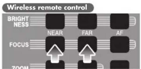

flowchart
graph LR
    A["NEAR"] --> B["FAR"]
    B --> C["AF"]

Limit of focus adjustment:
- With close-up lens TELE (Telescopic) : 250 - 410mm (9.8 - 16.1 in) from close-up lens WIDE (Wide-angle) : 85 - 410 mm (3.3 - 16.1 in) from close-up lens
- Without close-up lens TELE (Telescopic) : 500mm - ∞ (19.7 in - ∞) from zoom lens WIDE (Wide-angle) : 100mm - ∞ (3.9 in - ∞) from zoom lens

Even if the focus button on the WEB remote control is held down for a long time, the intended operation will not continue accordingly. To adjust the focus continuously, repeat clicking the focus button.
Brightness Adjustment
Front operating panel

Wireless remote control

WEB remote control

When either of the brightness adjustment buttons [💡]
- ] on the front operation panel or either of the brightness adjustment buttons [NORMAL • ⚙️] on the wireless remote control or WEB remote control is pressed or clicked, the image brightness is adjusted through the adjustment of the lens iris. This adjustment is performed in 2 adjustment modes as described below. Each mode is set by selecting [BRIGHTNESS] on the OSD.
■Auto Brightness Adjustment
([Brightness] is set to [Auto] on the OSD.)
It is so set that the brightness to be tracked automatically can be adjusted.
When the brightness adjustment buttons [●] and
[●] on the front operation panel are pressed together or the [NORMAL] button on the wireless remote control or WEB remote control is pressed or clicked, the current settings are reset to the default settings.
■Manual Brightness Adjustment
([Brightness] is set to [Manual] on the OSD.)
It is set so that the brightness can be locked to any level.
Wireless remote control

WEB remote control


The default setting is [Auto] (Auto Brightness Adjustment).

In the Manual Brightness Adjustment, the brightness is locked and the change in the object brightness is not tracked.

When adjusting the brightness manually, even if the brightness buttons [ ] and [ NORMAL] on the front operation panel are pressed together or the [NORMAL] button on the wireless remote control or WEB remote control is pressed or clicked, nothing will work.

When [Guide] is set to [On] on the OSD, the setting contents are displayed on the screen.

When any button on the WEB remote control is clicked once, operation continues at regular intervals.
State Presetting
The setting position of this product can be saved/called. Up to 8 positions can be saved. The presets that can be saved are as follows:
- Current zoom field angle (Optical zoom range)
- Brightness status
- White Balance state
• R-Gain (When the white balance is set to Manual)
• B-Gain (When the white balance is set to Manual) - Edge Effect settings (When Graphics mode is selected)
• Gamma value settings (When Graphics mode is selected) - Lighting ON/OFF
• Color/B&W selection settings
• Image Rotation state - Mode settings
- Posi/Nega settings
- Microphone volume
Wireless remote control


The saved state can be retained even if the power supply is turned OFF.

Rotated position cannot be saved to "Power On" setting. (Memory No.8 on remote control)

The zoom angle of the digital zoom is not saved. When the digital zoom status is saved, the zoom angle to be saved is to the full extent of the telescopic [ ] side of the optical zoom range.
■Presetting
When the [PRESET] button on the wireless remote control is pressed and then "within 4 seconds", the memory number button on the wireless remote control is pressed, the present camera using status is memorized in the selected memory number.
When the [PRESET] button on the wireless remote control is pressed and then the memory number [8] button on the wireless remote control is pressed, the contents of this setting are called when the power is turned on the next time.
Calling
When the [CALL] button on the wireless remote control is pressed and then "within 4 seconds", the memory number button on the wireless remote control is pressed, the settings of the selected memory number are called. When [Call] →[Default] on the OSD are selected, the factory-set settings are called.
Wireless remote control

flowchart
graph TD
    A["1"] --> B["2"]
    B --> C["3"]
    C --> D["4"]
    D --> E["5"]
    E --> F["6"]
    F --> G["7"]
    G --> H["8"]
    H --> I["9"]
    I --> J["10"]
    J --> K["11"]
    K --> L["12"]
    L --> M["13"]
    M --> N["14"]
    N --> O["15"]
    O --> P["16"]
    P --> Q["17"]
    Q --> R["18"]
    R --> S["19"]
    S --> T["20"]
Wireless remote control

flowchart
graph TD
    A["1"] --> B["2"]
    B --> C["3"]
    C --> D["4"]
    D --> E["5"]
    E --> F["6"]
    F --> G["7"]
    G --> H["8"]
    H --> I["9"]
    I --> J["10"]
    J --> K["11"]
    K --> L["12"]
    L --> M["13"]
    M --> N["14"]
    N --> O["15"]
    O --> P["16"]
    P --> Q["17"]
    Q --> R["18"]
    R --> S["19"]
    S --> T["20"]
    T --> U["21"]
    U --> V["22"]
    V --> W["23"]
    W --> X["24"]
    X --> Y["25"]
Microphone Input
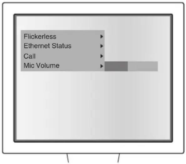
Adjusting the microphone volume
When [▶] of [Mic Volume] is pressed on the OSD, the volume level bar is displayed. Then, adjust the volume by using the direction buttons [▲▼] on the wireless remote control.

When the volume is brought to the left end of the level bar, the microphone falls into the mute status.
White Balance
■How to use [Auto]
To be used for adjusting the white coloring automatically according to the status of the document.
Default setting as of the shipment from our factory is [Auto].
■How to use [One-Push]
To be used in case of the disruption of the image color balance due to the document status.
■How to use [Manual]
When [White Balance] is set to [Manual] on the OSD, the white balance is fixed, and furthermore, [R-Gain] and [B-Gain] can be adjusted on the OSD.
![Elmo P100N - ■How to use [Manual] - 1](/content/2026/05/957650/images/e05760c0aa5b06a99ee381087c984e40dcde1aaea7f074c5a9220d50a15f65c4.jpg)
The color temperature range that can be followed automatically is around 3000K — 8000K.
![Elmo P100N - ■How to use [Manual] - 2](/content/2026/05/957650/images/f493df425c76f06e510ce98d9c9a61108a6405a9f177e937ea5e0474061dd4b2.jpg)
When [Guide] is set to [On] on the OSD, the setting details are displayed on the screen.
![Elmo P100N - ■How to use [Manual] - 3](/content/2026/05/957650/images/0aa69f88dc12d440025a443f26907355c5a728f6173faed340e963b13cc06301.jpg)
If the precise automatic adjustment is impossible due to the object or light source, adjust the white coloring automatically by imaging a white object, and set [White Balance] to [One-Push] on the OSD.
6 RS-232C SPECIFICATIONS
This product can be controlled from a PC connected to this product through the RS-232C terminal [RS-232C].
Setting Up
①Connect this product to a PC with an RS-232C cable.

When using an RS-232C cable available on the market, make sure that pin connections are the same as below.

To protect this product and the PC, be sure to turn OFF the power supply to all units before starting the connection work.
②Start the PC, and set the communication mode of the RS-232C to the communication mode of this product.

For the information how to set the communication mode of the RS-232C, refer to the instruction manual of the PC.
③Start the PC program to operate this product.
④Control through the RS-232C will start.

For communication control, be sure to take the above steps for settings.
Cable Connection
This product side (DSUB-9P)
DSUB-9P (Female)

CD 1 RXD 2 TXD 3 DTR 4 SG 5 DSR 6 RTS 7 CTS 8 RI (CI) 9
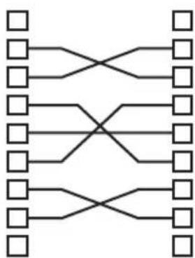
flowchart
graph TD
    A1[" "] --> B1[" "]
    A2[" "] --> B2[" "]
    A3[" "] --> B3[" "]
    A4[" "] --> B4[" "]
    A5[" "] --> B5[" "]
    A6[" "] --> B6[" "]
    A7[" "] --> B7[" "]
    A8[" "] --> B8[" "]
    A9[" "] --> B9[" "]
    A10[" "] --> B10[" "]
    A11[" "] --> B11[" "]
    A12[" "] --> B12[" "]
    A13[" "] --> B13[" "]
    A14[" "] --> B14[" "]
    A15[" "] --> B15[" "]
    A16[" "] --> B16[" "]
    A17[" "] --> B17[" "]
    A18[" "] --> B18[" "]
    A19[" "] --> B19[" "]
    A20[" "] --> B20[" "]
    A21[" "] --> B21[" "]
    A22[" "] --> B22[" "]
    A23[" "] --> B23[" "]
    A24[" "] --> B24[" "]
    A25[" "] --> B25[" "]
    A26[" "] --> B26[" "]
    A27[" "] --> B27[" "]
    A28[" "] --> B28[" "]
    A29[" "] --> B29[" "]
    A30[" "] --> B30[" "]
    A31[" "] --> B31[" "]
    A32[" "] --> B32[" "]
    A33[" "] --> B33[" "]
    A34[" "] --> B34[" "]
    A35[" "] --> B35[" "]
    A36[" "] --> B36[" "]
    A37[" "] --> B37[" "]
    A38[" "] --> B38[" "]
    A39[" "] --> B39[" "]
    A40[" "] --> B40[" "]
    A41[" "] --> B41[" "]
    A42[" "] --> B42[" "]
    A43[" "] --> B43[" "]
    A44[" "] --> B44[" "]
    A45[" "] --> B45[" "]
    A46[" "] --> B46[" "]
    A47[" "] --> B47[" "]
    A48[" "] --> B48[" "]
    A49[" "] --> B49[" "]
    A50[" "] --> B50[" "]
    A51[" "] --> B51[" "]
    A52[" "] --> B52[" "]
    A53[" "] --> B53[" "]
    A54[" "] --> B54[" "]
    A55[" "] --> B55[" "]
    A56[" "] --> B56[" "]
    A57[" "] --> B57[" "]
    A58[" "] --> B58[" "]
    A59[" "] --> B59[" "]
    A60[" "] --> B60[" "]
    A61[" "] --> B61[" "]
    A62[" "] --> B62[" "]
    A63[" "] --> B63[" "]
    A64[" "] --> B64[" "]
    A65[" "] --> B65[" "]
    A66[" "] --> B66[" "]
    A67[" "] --> B67[" "]
    A68[" "] --> B68[" "]
    A69[" "] --> B69[" "]
    A70[" "] --> B70[" "]
    A71[" "] --> B71[" "]
    A72[" "] --> B72[" "]
    A73[" "] --> B73[" "]
    A74[" "] --> B74[" "]
    A75[" "] --> B75[" "]
    A76[" "] --> B76[" "]
    A77[" "] --> B77[" "]
    A78[" "] --> B78[" "]
    A79[" "] --> B79[" "]
    A80[" "] --> B80[" "]
    A81[" "] --> B81[" "]
    A82[" "] --> B82[" "]
    A83[" "] --> B83[" "]
    A84[" "] --> B84[" "]
    A85[" "] --> B85[" "]
    A86[" "] --> B86[" "]
    A87[" "] --> B87[" "]
    A88[" "] --> B88[" "]
    A89[" "] --> B89[" "]
    A90[" "] --> B90[" "]
    A91[" "] --> B91[" "]
    A92[" "] --> B92[" "]
    A93[" "] --> B93[" "]
    A94[" "] --> B94[" "]
    A95[" "] --> B95[" "]
    A96[" "] --> B96[" "]
    A97[" "] --> B97[" "]
    A98[" "] --> B98[" "]
    A99[" "] --> B99[]
PC side (DSUB-9P)
1 CD
2 RXD
3 TXD
4 DTR
5 SG
6 DSR
7 RTS
8 CTS
9 RI
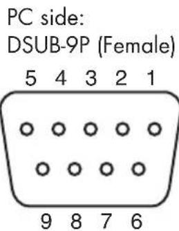
Data Format Specification
This command is executed in the form of 1-command/1-packet. The next command is not accepted until the previous processing is completed.
- The communication command always starts with STX (Start of Text), and ends with ETX (End of Text).
- If the communication format of command name is wrong, NAK (Negative Acknowledge) will be sent from this product as a result of failing to receive correctly.
- When communication format is received correctly, this product sends ACK (Normal Acknowledge).
■ Operation Command (PC → This product)
Each operation command is executed in ASCII code, and transmitted in a set of 7 bytes as follows:
| S | Command | Parameter | Data | E |
| T | T | |||
| X | X |
(This product) → ACK
■ Response Data Format (This product → PC)
All response data is transmitted as ASCII code, corresponding to the parameters in the operation command table.
- Status 0
| STX | Lighting | Status display | Posi/Nega | Color/B&W | Display mode | Display | Pause | Flickerless | ETX |
- Status 2
| STX | Brightness mode | Gamma selection | Image rotation | Edge effect | White balance | Text | Video output | USB Mode/Ethernet | ETX |
- ROM Ver0 (MASTER)
| STX | V56H | H48H | N4EH | **H | **H | **H | ETX |
- ROM Ver1 (SLAVE)
| STX | V56H | H48H | N4EH | **H | **H | **H | ETX |
- ROM Ver2 (LENS)
| STX | V56H | H48H | N4EH | **H | **H | **H | ETX |
- ROM Ver3 (MAIN) ... Upper 6 bytes
| STX | **H | **H | **H | **H | **H | **H | ETX |
- ROM Ver4 (MAIN) ... Lower 4 bytes
| STX | **H | **H | **H | **H | 20H | 20H | ETX |
Transmission Specifications
• Full duplex start-stop sync. mode
- Start bit : 1 bit
- Data bit : 8 bits
- Stop bit : 1 bit
- Parity bit : None
- X parameter : None
- Baud rate (Communication speed) : 9600bps
UART Communication Format
Commands, parameters and data are all transmitted in ASCII code.
| Function | Command | Parameter | Data | Contents |
| Auto Focus | AF 0 ■■ | To perform the one-shot auto focus | ||
| Focus adjustment | FO | + (Near) | ■■ | To adjust the focus |
| - (Far) | ||||
| 0 (Stop) | ||||
| Zoom adjustment | ZO | + (Tele) | ■■ | To adjust the zoom |
| - (Wide) | ||||
| 0 (Stop) | ||||
| Brightness adjustment | IR | + (Open) | ■■ | To adjust the brightness |
| - (Close) | ||||
| 0 (Stop) | ||||
| 1 (Auto) | ||||
| 2 (Manual) | ||||
| Lighting selection | PL | 0 (OFF) | ■■ | To turn ON/OFF the lighting |
| 1 (BASE) | ||||
| 2 (UPPER) | ||||
| Display mode selection | AV | 0 (Camera) | ■■ | To switch the display mode |
| 1 (RGB IN) | ||||
| 2 (SD) | ||||
| Video output selection | MO | 0 (All Mode) | ■■ | To switch the video output |
| 1 (Camera & SD) | ||||
| Direction | KE | 0 (Menu) | ■■ | To scroll in the direction indicated by arrow when the digital zoom is in operationTo select and determine an image on the split screen |
| 1 (Enter) | ||||
| 2 (→) | ||||
| 3 (←) | ||||
| 4 (↑) | ||||
| 5 (↓) | ||||
| Pause | FZ | 0 (OFF) | ■■ | To freeze the image |
| 1 (ON) | ||||
| Guide | GU | 0 (OFF) | ■■ | To set whether the main unit operation state should be displayed on the screen or not |
| 1 (ON) | ||||
| Display | DP | 0 (Single) | ■■ | To select whether the images in the SD card mode should be displayed on the split screen or not |
| 1 (3×3) | ||||
| 2 (4×4) | ||||
| Slide show | SS | 0 (Stop) | ■■ | To start/stop the slide show |
| 1 (Start) | ||||
| Slide-show image feed effect 1 (LT to RB)2 (RT to LB) | SE | 0 (Left to right) | ■■(None) | To set the visual effect of the slide show |
| 3 | ||||
| Slide-show object file | ST | 0 (All) | ■■ | As a slide show target, select all images stored on the SD card or only the locked image files |
| 1 (Locked) | ||||
| Slide-show feed order | SO | 0 (FWD) | ■■ | To set whether the slide show should be proceeded in the ascending order or in the descending order |
| 1 (BWD) | ||||
| Slide-show image feed interval2 (10s)3 (15s)4 (30s) | SI | 0 (3s) | ■■ | To set the interval of the image switching in the slide show |
| 1 (5s) | ||||
| Slide-show repeat 1 | SR(ON) | 0 (OFF) | ■■ | To proceed the slide show repeatedly |
| File delete1 (All) | DE | 0 (Current) | ■■ | To delete an image file in the SD card |
| File lock1 (All) | SL | 0 (Current) | ■■ | To lock an image file in the SD card |
| File unlock1 | SU(All) | 0 (Current) | ■■ | To unlock the locked image file in the SD card |
| Format | SF | 0 | ■■ | To format the SD card |
| Image save | CA | 0 | ■■ | To save the image on the SD card or FTP-transfer the image |
| USB Mode/Ethernet switching | UM1 (Application) | 0 (Mass Storage) | ■■(Ethernet) | To switch the USB Mode/Ethernet |
| 4 | ||||
| Gamma setting1 (Normal)2 (Low) | GM | 0 (High) | ■■ | To set the gamma value of the image |
| Flicker-less | FL | 0 (60Hz) | ■■(50Hz) | To set the flicker-less |
| 1 | ||||
| Microphone volume adjustment | MV | + (UP) | ■■ | To adjust the microphone volume |
| - (DOWN) | ||||
| Capture mode switching | CM | 0 (SD) | ■■ | To switch the Capture mode |
| 1 (Ethernet) | ||||
| Ethernet default | ED | 0 | ■■ | To reset the Ethernet status to the default setting status |
ENGLISH
| Function | Command | Parameter | Data | Contents |
| Image rotation | RO | 0 (0°) | ■■(180°) | To turn the image |
| 1 | ||||
| Edge effect | AP | 0 (OFF) | ■■ | To set the edge enhancement |
| 1 (Low) | ||||
| 2 (Mid) | ||||
| 3 (High) | ||||
| White balance | AW | 0 (Manual) | ■■ | To switch the white balance mode |
| 1 (Auto) | ||||
| 2 (One Push) | ||||
| 3 (R_Up) | ||||
| 4 (R_Down) | ||||
| 5 (B_Up) | ||||
| 6 (B_Down) | ||||
| Text | CT | 0 (GRAPHICS) | ■■(TEXT2)(TEXT3) | To set the contrast |
| 1 (TEXT1) | ||||
| 2 | ||||
| 3 | ||||
| Posi/Nega | NP | 0 (Posi) | ■■ | To set the Posi/Nega |
| 1 (Nega) | ||||
| Color/B&W | CB | 0 (Color) | ■■ | To set the Color/B&W |
| 1 (B&W) | ||||
| Local lockout | LL | 0 (OFF) | ■■ | To invalidate the operations of the front operation panel and the wireless remote control |
| 1 (ON) | ||||
| Default | DF | 0 | ■■ | To reset to the default settings |
| Status request | QS | 0 | ■■ | To inquire about the status of the camera system |
| 2 | ||||
| ROM version | QR | 0 | ■■ | To inquire about the ROM version |
| 1 | ||||
| 2 | ||||
| 3 | ||||
| 4 | ||||
| ACK check | SA | 0 (OFF) | ■■ | To switch the ACK check mode |
| 1 (ON) | ||||
| CR addition | SC | 0 (OFF) | ■■(ON) | To switch the CR addition settings |
| 1 |

For "■■" in the data column, transmit the SPACE [20H] twice.
Connection
If the RS-232C cable is not connected correctly between this product and the PC, no acknowledgement is transmitted.
Connect the RS-232C cable correctly, and fix it firmly with the connector set screws before starting the operation.
7
TROUBLESHOOTING
Symptoms and Confirmation
Check the following items. If any abnormality is found, consult the seller from whom you have purchased this product or our branch/office near your location.
| Symptom Check this item | |
| No image is displayed on the TV monitor. monitor. | The cable is not connected correctly to the video-in terminal of the The power cord is disconnected from the wall AC outlet.The DC cord plug of the AC adapter is off the power socket of this camera system.The power switch is not ON.Zoom is set at the TELE side, displaying only the white/black part of the document.The power switch is turned ON immediately after it is turned OFF.In this case, this product may not start immediately. Wait for several seconds after turning OFF the power switch, and then turn it ON. |
| The image is out of • The document (object) is too close to the lens.focus. • Zoom is at the TELE side after focusing at a wide angle (at the WIDE side). Focus on the point of max. at the TELE side.In the auto focus, focusing is difficult in some cases. | |
| The lamp does not • For light up quickly. preheating | the protection purpose, the lamp is arranged to light up after 2 seconds. This is not a fault. |
| The video output image is disarrayed. system | The video output is set to the PAL system. If this product, set to the PAL system, is connected to the monitor specially designed for the NTSC system, the video image may not be outputted normally but be disarrayed or in black and white. In such case, switch the system of the video output by referring to "DIP Switch" at P. 75. |
| The image is too dark. • | The intensity of the lighting is not sufficient. Press the [icon] button on the front operating panel or wireless remote control to turn ON the lamp.The brightness has been adjusted to the close side. Adjust the brightness so that the image can become bright. |
| The image is striped. • This may be interference fringes between dots of printed matter and TV scanning lines or CMOS pixels. This may be mitigated by changing the projection range.When using an LCD projector, vertical stripes may appear on the screen. This may be mitigated by manually adjusting the dot clock frequency on the projector side. | |
| The brightness tone is • out of order. | This may be mitigated by switching gamma settings. |
| The material (object) does not come to the center of the display | Initialize the camera position by referring to P. 90. |
| The microphone volume is not output. | Only the microphone for PCs (electret condenser microphone) can be connected to [MIC IN]. Before connection, carefully check the specifications of the microphone. |
| The network function does not operate. | Reconfirm this camera system and the network configuration of the PC to be connected to this camera system, and then, cross-check them with the phenomena described below.Reconfirm the restrictive conditions (e.g., number of connections) and the setting details of this camera system, as well. |
| The network operationis unstable. 1. The OS inst | The WEB connection works only in the following environment:stalled is Microsoft Windows2000/XP/Vista.JRE1.5.0_12 or newer has been installed and Java (Sun) is valid.Internet Explorer6 or 7 has been installed. |
| The LAN cable cannotbe connected. | The LAN connector (RJ45) is located on the main unit side. |
| The LAN connector linklamp (orange LED) to thiscannot light up. then turn | Power is not supplied to this camera system or the unit to be connectedcamera system. Check whether the cable is connected firmly, andON the power supply. |
| The cable is disconnected. Check the conduction between the cableterminals. | |
| The cable used is wrong. Basically, when the unit to be connected tothis camera system is a PC, “cross cable” or “LAN cross cable (attachedto this camera system)” is used, and when it is a hub or router, “straightcable” is used. Actually, the specifications of the unit should bechecked. | |
| Connection from theclient is impossible. Designate the IP address set in this camera system. | The IP address of this camera system has not been designated. |
| The IP address of the client is not compatible with the network of thiscamera system. To establish the connection from the client to thiscamera system, the network address (192.168.1.* when this camerasystem settings are default) should be the same between the client andthis camera system.* If the IP address of this camera system has escaped your memory,refer to “IP Address” (P. 77) or “Ethernet” (P. 78) of the OSD. | |
| The router settings are wrong. Check the network configuration of thiscamera system and the client, and set the router accordingly. | |
| The networkconfiguration page logincannot be accessed. | The authority “user” was used for login. Use the authority “root” for |
| The FTP clientconfiguration pagecannot be accessed. | Use the authority “root” or “user” for login. |
| Image capture throughthe network is impossible. | [USB Mode/Ethernet] has not been set to [Ethernet] on the OSD. |
| The mode is not the camera mode. The camera image cannot becaptured in the SD mode. | |
| [PAUSE] is working in the camera mode. | |
| Image capture throughImage Mate is impossible. | [USB Mode/Ethernet] has not been set to [Application] on the OSD. |
| Image capture throughthe FTP client isimpossible. | [Capture] has not been set to [Ethernet] on the OSD. |
| Image cannot be savedon the SD card. | [Capture] has not been set to [SD] on the OSD. |
Replacement of Lighting Lamp (Fluorescent Lamp)
The lighting lamps (fluorescent lamps) are expendables. When any of them begins to shimmer or dim, replace it.

For the replacement of the lamp, consult the dealer from whom you have purchased this product or our branch/office near your location.
About the long-time use
When this camera system is used for a long time exceeding the warranty period or it is used for a long time with the power always ON, the performance or quality of this camera system could be degraded due to the expiry of the service life of some parts. In this case, the exhausted parts can be replaced with payment. For this replacement, contact the sales outlet from which you have purchased this camera system or the nearest branch office or sales office of ours.
8 SPECIFICATIONS
■General
| Item Specifications | ||
| Power source 12VDC (AC adapter: 100 ~ 240VAC) | ||
| Power consumption 35W (AC adapter included) | ||
| Outside dimensions | 457×562×138mm (18.0×22.1×5.4 in) (When folded) | |
| 457×519×587mm (18.0×20.4×23.1 in) (When set up) | ||
| Weight Approx. 8.5kg | (18.7 lbs) (Main body only) | |
| Input selection Main body / External one system | ||
| Output terminal DVI output DVI-D 24P connector | female ×1 | |
| RGB output Mini DSUB 15P connector, female ×1 | ||
| Composite video output RCA pin jack / 75Ω unbalanced ×1 (NTSC/PAL) | ||
| Audio output (stereo) RCA pin jack / compatible impedance ×1 1kΩ or more 300mV (rms) | ||
| Input terminal | RGB input | Mini DSUB 15P connector, female ×1 |
| Audio input (stereo) | 300mV (rms) impedance ×1 20 kΩ or more φ3.5mm stereo mini jack | |
| Microphone input (mono) | φ3.5mm jack / compatible impedance ×1 6.9kΩ 30mV (rms) | |
| Ext. control terminal | RS-232C | Dsub 9P connector, male ×1 |
| USB (2.0 compliant) | Type B receptacle ×1 | |
| Ethernet | 8-core modular type (RJ-45) ×1 | |
| Memory interface | SD card slot | ×1 |
■Microphone input circuit

■Main Camera
| Item Specifications | ||
| Lens f = 4.9 ~ 78.4mm (16-time zoom), F = 2.7 | ||
| Shooting speed 30 frames/sec | ||
| Shooting area | SXGA 405×324mm (15.9×12.8 in) max. 30×24mm (1.2×0.9 in) min.HDTV 405×224mm (15.9×8.8 in) max. 30×17mm (1.2×0.7 in) min.XGA 405×303mm (15.9×11.9 in) max. 30×23mm (1.2×0.9 in) min. | |
| Limit of focus With close-up adjustment TELE side : 250 | lens:~ 410mm (9.8 ~ 16.1 in) from close-up lensWIDE side : 85 ~ 410mm (3.3 ~ 16.1 in) from close-up lensWithout close-up lens:TELE side : 500mm ~∞ (19.7 in ~∞) from zoom lensWIDE side : 100mm ~∞ (3.9 in ~∞) from zoom lens | |
| Optical zoom 16× | ||
| Digital zoom 4× | ||
| Focus Auto/Manual | ||
| Brightness Auto (level adjustable) / Manual | ||
| Image pick-up element 1/3' | 1.3M CMOS | |
| Total picture elements Horizontal 1312, Vertical 1032 ... Approx. 1,350,000 pixels | ||
| Effective picture elements SXGA Horizontal 1280, Vertical 1024HDTV Horizontal 1280, Vertical 720XGA Horizontal 1280, Vertical 960 | ||
| Synchronizing system | Internal | |
| Resolution Analog RGB output:Horizontal 800TV lines or more Vertical 800TV lines or moreVideo output:Horizontal 450TV lines or more | ||
| DVI output | TMDS data signal 0.5 (Vp-p)50Ω(Terminated) | SXGA: Horizontal frequency 63.98kHz; Vertical frequency 60.02Hz (1280×1024 at 60Hz); Compliant with VESA HDTV: Horizontal frequency 44.7kHz; Vertical frequency 60Hz (1280×720 at 60Hz); Compliant with HDTV XGA: Horizontal frequency 48.363kHz; Vertical frequency 60.004Hz (1024×768at 60Hz); Compliant with VESA |
| Analog RGB output | 0.7 (Vp-p) 75Ωunbalanced,Synchronized signal: SXGA Positive polarityHDTV Negative polarityXGA Negative polarity | |
| Composite video output | Compliant with NTSC/PAL | |
| White balance | Full auto / One-push / Manual | |
| Video output selection | Provided (NTSC/PAL) | |
| Posi/Nega conversion | Provided | |
| Color/B&W selection | Provided | |
| Image rotation | Provided (0°/180°, Automatic rotation by 180° for forward shooting) | |
| Text mode | Text1 / Text2 / Text3 / GRAPHICS | |
| Gamma setting | Provided (GRAPHICS mode only) | |
| Edge enhancement | Provided (GRAPHICS mode only) | |
| Pause | Provided | |
| Image recording | Provided (SD card) | |
| Split display | Provided (SD card image / 9-splits / 16-splits) | |
| Slide show | Provided (SD card image) | |
ENGLISH
■Network
| Item Specifications | |
| Interface 10BASE-T/100BASE-TX (RJ-45) | |
| Compliant protocol | IP, ARP, ICMP, TCP, HTTP, FTP, telnet |
| Recommended browser | Internet Explorer6.0 or newer |
| Compliant OS | Windows2000 (SP4 or newer)/XP (SP2 or newer)/Vista |
| Connection port No. | HTTP:80, FTP:20,21, telnet:23 |
| Compliant language | Japanese, English |
| Image format Motion-JPEG | |
| Image size SXGA: Horizontal 1280, Vertical 1024HDTV: Horizontal 1280, Vertical 720XGA: Horizontal 1280, Vertical 960 | |
| Frame rate Max. approx. 5fps | |
| Number of clients simultaneously connectable to live screen | 5 clients |
| Number of clients simultaneously connectable to FTP server | 1 clients |
| Still image display | JPEG |
| Main unit remote function | ZOOM, LAMP, BRIGHTNESS, FOCUS, GRAPHICS, TEXT, EDGE EFFECT, IMAGE ROTATION, POSI/NEGA, COLOR/B&W |

This camera system can be remote-controlled or the status of this camera system can be captured by using the telnet. For the information of its command, etc., contact the sales outlet from which you have purchased this camera system or the nearest branch office or sales office of ours.
Lighting
| Item Specifications | |
| Lighting | High frequency lighting mode, twin fluorescent lamp, Type 9 (Model: FPL9EX-N) |
| Base illumination | Cold-cathode tube |
■Supplied Accessories
| Name Quantity | |
| Power adapter 1 | |
| Power cord (1.5m) 1 | |
| Video cable (RCA pin connector) (3m) 1 | |
| Analog RGB cable (DSUB 15P connector) (2m) 1 | |
| DVI cable (2m) 1 | |
| Infrared wireless remote control 1 | |
| Batteries (Type R03, AAA) 2 | |
| Instruction Manual for P100N 1 | |
| Warranty Card for P100N | 1 |
| USB cable (1.8m) | 1 |
| Utility Software Installation Manual | 1 |
| Utility Software CD-ROM | 1 |
| Ethernet cross cable (1m) | 1 |

For the RCA pin, use a pin plug compliant with EIAJ RC-6703.

The above specifications are subject to change without notice.
Copyright, License, etc.
The software contained in this camera system is composed of several independent components. Some of them are applied with GPL/LGPL.
This camera system contains free software "thttpd" of ACME Labs.
thttpd. Copyright© 2000 by Jef Poskanzer jef@mail.acme.com. All rights reserved.
For the information of GPL/LGPL and ACME Labs Freeware License, access to the following URL for reference:
http://(IP address of this camera system)/license.html
Disclaimers
Please be informed that Elmo shall not be liable at all to any damage, direct or indirect, caused by the use of our Ethernet function.
Depending on the software installed in your PC or peripheral unit connected to your PC, the functional operation of the Ethernet of this camera system could be affected.
Trademark Acknowledgements
ELMO is a trademark of ELMO Co., Ltd.
VESA and SVGA are registered trademarks of Video Electronics Standards Association.
SXGA, VGA and XGA are trademarks or registered trademarks of International Business Machines Corporation.
SD : SD logo is a trademark.
Microsoft, Windows, Internet Explored are registered trademarks of Microsoft Corporation in the United States and other counties.
Java is a trademark of Sun Microsystems, Inc.
Any other company names and product names appeared in this manual are trade names, trademarks or registered trademarks of the respective relevant companies.
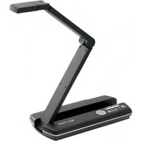


- IMPORTANT SAFEGUARDS
- ENGLISH
- CAUTION
- FOR UNITED STATES USERS:
- INFORMATION
- USER-INSTALLER CAUTION:
- BEFORE YOU USE
- CONTENTS
- PART NAMES AND FUNCTIONS
- SETTING UP
- STORING
- VARIOUS FUNCTIONS AND OPERATIONS
- RS-232C SPECIFICATIONS
- TROUBLESHOOTING
- SPECIFICATIONS
- PART NAMES AND FUNCTIONS
- Name of Each Part
- Functions
- ■Front Operating Panel
- Rear Panel
- ■Side Panel
- OSD (On-Screen Display)
- Wireless Remote Control
- ■Receivable Range
- - Receivable range
- Battery Change
- WEB Screen
- ■Top page
- LIVE
- ■REFRESH
- ■CONFIGURATIONS
- CONFIGURATIONS
- ■ Network Configuration
- ■FTP Client Configuration
- SETTING UP
- Setting Up
- Connecting Cables
- ①Connecting to the PC with a USB cable
- ②Connecting to the unit having the DVI input terminal
- ③Connecting to the unit having the analog RGB input terminal
- ④Connecting to the unit having the analog RGB output terminal
- ⑤Connecting to the unit having the composite video input terminal
- ⑥Connecting to the microphone
- ⑦Connecting to the PC and the network with the Ethernet cable
- ⑧Connecting to the speaker
- ⑨Connecting to the audio reproducer
- STORING
- Storing
- Turning ON/OFF the Power Supply
- Presentation by Using Documents, Films, etc.
- Presentation using optional SD card (Option)
- Presentation using optional SD card (Option) (Continued)
- ■Saving the Image
- ■Displaying the image
- ■Deleting the Image
- ■Slide show
- ■Formatting the SD card
- Presentation using the supplied software with the USB-connected PC
- Transferring the images from the SD card into the USB-connected PC
- Displaying the Video Image through Network Connection
- Capturing the Image through Network Connection with the FTP
- The following 2 functions are available:
- Using [MIC IN] and [AUDIO IN]
- Shooting off the stage
- VARIOUS FUNCTIONS AND OPERATIONS
- Lighting
- Zoom
- ●Zoom magnification in the Camera mode
- Image Selection
- Focus
- ■Auto Focus
- ■Manual Focus
- Brightness Adjustment
- ■Auto Brightness Adjustment
- ■Manual Brightness Adjustment
- State Presetting
- ■Presetting
- Calling
- Microphone Input
- White Balance
- ■How to use [Auto]
- ■How to use [One-Push]
- ■How to use [Manual]
- RS-232C SPECIFICATIONS
- Cable Connection
- Data Format Specification
- ■ Operation Command (PC → This product)
- ■ Response Data Format (This product → PC)
- Transmission Specifications
- UART Communication Format
- Connection
- 7
- TROUBLESHOOTING
- Symptoms and Confirmation
- Replacement of Lighting Lamp (Fluorescent Lamp)
- About the long-time use
- SPECIFICATIONS
- Copyright, License, etc.
- Disclaimers
- Trademark Acknowledgements
Brand : Elmo
Model : P100N
Category : Document Camera