
351.217480 - Drill Craftsman - Free user manual and instructions
Find the device manual for free 351.217480 Craftsman in PDF.


| Product Type | 13" Thickness Planer |
| Brand | Craftsman |
| Model | 351.217480 |
| Overall Dimensions | 25 1/2" W × 34 1/5" D × 24 1/4" H |
| Weight | 94 lbs |
| Table Size | 13" × 9 3/4" (with extension tables: 14" × 12") |
| Power Source | 120 V, 15 A, 60 Hz, Single Phase |
| Motor | 15 Amp Universal Motor |
| Cutterhead Speed | 10,000 RPM |
| Maximum Workpiece Width | 13" |
| Maximum Workpiece Thickness | 6" |
| Maximum Depth of Cut | 1/8" (for pieces up to 6" wide); 3/32" for 6-13" wide |
| Feed Rate | 26 FPM |
| Number of Blades | 3 (reversible) |
| Depth-of-Cut Gauge | Yes, up to 3/32" |
| Workpiece Thickness Pre-set | 8 positions: 1/8", 1/4", 1/2", 3/4", 1", 1-1/4", 1-1/2", 1-3/4" |
| Switch | ON/OFF with removable key for lock |
| Circuit Breaker | Manual reset overload protector |
| Dust Collection | Includes dust chute and exhaust adapter |
| Warranty | One-year full warranty |
| Included Accessories | Magnetic blade removal tool, 4mm T-handle hex wrench, dust chute, exhaust adapter, handle with knob |
Frequently Asked Questions - 351.217480 Craftsman
User questions about 351.217480 Craftsman
0 question about this device. Answer the ones you know or ask your own.
Ask a new question about this device
Download the instructions for your Drill in PDF format for free! Find your manual 351.217480 - Craftsman and take your electronic device back in hand. On this page are published all the documents necessary for the use of your device. 351.217480 by Craftsman.
USER MANUAL 351.217480 Craftsman

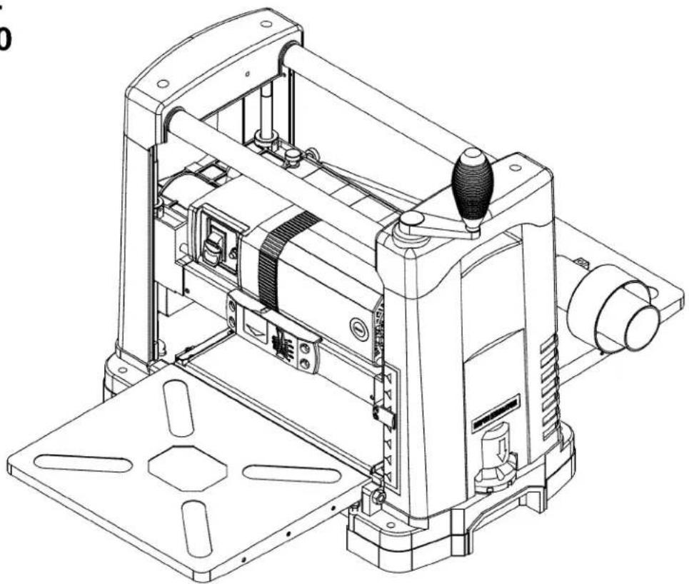
13"
THICKNESS PLANER
Model No.
351.217480
natural_image
Technical line drawing of a mechanical device with no visible text or symbolsCAUTION: Read and follow all Safety Rules and Operating Instructions before First Use of this Product. Keep this manual with tool.
Sears Brands Management Corp., Hoffman Estates, IL 60179 U.S.A.
www.sears.com/craftsman
30783.00 Draft (10/07/09)
TABLE OF CONTENTS
Warranty....2
Safety Rules 2-3
Unpacking 3
Assembly 3-4
Installation....4-5
Operation 5-8
Maintenance 8-9
Troubleshooting 10
Parts Illustration and List 12-15
Español....16-26
WARRANTY
ONE-YEAR FULL WARRANTY ON CRAFTSMAN PROFESSIONAL TOOL
If this Craftsman tool fails due to a defect in material or workmanship within one year from the date of purchase, call 1-800-4-MY-HOME® TO ARRANGE FOR FREE REPAIR (or replacement if repair proves impossible).
This warranty does not include expendable parts, such as lamps, batteries, bits or blades.
If this tool is ever used for commercial or rental purposes, this warranty will apply for only 90 days from the date of purchase.
This warranty gives you specific legal rights and you may also have other rights which vary from state to state.
Sears, Roebuck and Co., Hoffman Estates, IL 60179
SAFETY RULES
WARNING: For your own safety, read all of the rules and precautions before operating tool.
PROPOSITION 65 WARNING: Some dust created by power sanding, sawing, grinding, drilling and other construction activities contains chemicals known to the state of California to cause cancer, birth defects or other reproductive harm.
Some examples of these chemicals are:
- Lead from lead-based paints.
- Crystalline silica from bricks and cement and other masonry products.
- Arsenic and chromium from chemically-treated lumber.
Your risk from these exposures vary, depending on how often you do this type of work. To reduce your exposure to these chemicals: work in a well ventilated area and work with approved safety equipment. Always wear OSHA/NIOSH approved, properly fitting face mask or respirator when using such tools.
CAUTION: Always follow proper operating procedures as defined in this manual even if you are familiar with use of this or similar tools. Remember that being careless for even a fraction of a second can result in severe personal injury.
BE PREPARED FOR JOB
- Wear proper apparel. Do not wear loose clothing, gloves, neckties, rings, bracelets or other jewelry which may get caught in moving parts of machine.
- Wear protective hair covering to contain long hair.
- Wear safety shoes with non-slip soles.
- Wear safety glasses complying with United States ANSI Z87.1. Everyday glasses have only impact resistant lenses. They are NOT safety glasses.
- Wear face mask or dust mask if operation is dusty.
- Be alert and think clearly. Never operate power tools when tired, intoxicated or when taking medications that cause drowsiness.
PREPARE WORK AREA FOR JOB
- Keep work area clean. Cluttered work areas invite accidents.
- Do not use power tools in dangerous environments.
- Do not use power tools in damp or wet locations. Do not expose power tools to rain.
• Work area should be properly lighted. - Proper electrical receptacle should be available for tool. Three prong plug should be plugged directly into properly grounded, three-prong receptacle.
- Extension cords should have a grounding prong and the three wires of the extension cord should be of the correct gauge.
- Keep visitors at a safe distance from work area.
- Keep children out of workplace. Make workshop childproof. Use padlocks, master switches or remove switch keys to prevent any unintentional use of power tools.
TOOL SHOULD BE MAINTAINED
• Always unplug tool prior to inspection.
- Consult manual for specific maintaining and adjusting procedures.
- Keep tool lubricated and clean for safest operation.
- Remove adjusting tools. Form habit of checking to see that adjusting tools are removed before switching machine on.
- Keep all parts in working order. Check to determine that the guard or other parts will operate properly and perform their intended function.
- Check for damaged parts. Check for alignment of moving parts, binding, breakage, mounting and any other condition that may affect a tool's operation.
- A guard or other part that is damaged should be properly repaired or replaced. Do not perform makeshift repairs. (Use parts list provided to order replacement parts.)
KNOW HOW TO USE TOOL
- Use right tool for job. Do not force tool or attachment to do a job for which it was not designed.
-
Disconnect tool when changing blades.
-
Avoid accidental start-up. Make sure that the switch is in the OFF position before plugging in.
- Do not force tool. It will work most efficiently at the rate for which it was designed.
- Keep hands away from moving parts and cutting surfaces.
- Never leave tool running unattended. Turn the power off and do not leave tool until it comes to a complete stop.
- Do not overreach. Keep proper footing and balance.
- Never stand on tool. Serious injury could occur if tool is tipped or if blade is unintentionally contacted.
- Know your tool. Learn the tool's operation, application and specific limitations.
- Use recommended accessories (refer to page 13). Use of improper accessories may cause risk of injury to persons.
- Handle workpiece correctly. Protect hands from possible injury.
- Turn machine off if it jams. Blade jams when it digs too deeply into workpiece. (Motor force keeps it stuck in the work.)
- Always keep drive, cutterhead and blade guards in place and in proper operating condition.
- Feed work into blade or cutter against direction of rotation.
CAUTION: Think safety! Safety is a combination of operator common sense and alertness at all times when tool is being used.
WARNING: Do not attempt to operate tool until it is completely assembled according to the instructions.
UNPACKING
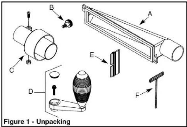
Refer to Figure 1 below.
Check for shipping damage. If damage has occurred, a claim must be filed with carrier. Check for completeness. Immediately report missing parts or damaged parts. Call 1-800-266-9079 to obtain replacement parts.
IMPORTANT: Remove protective paper from the table before operating unit.
The planer comes assembled as one unit. Additional parts which need to be fastened to planer should be located and accounted for before assembling.
A Dust Chute
B Thumb Screw (2)
C Exhaust Adapter Assembly
D Handle with Knob
E Magnet Blade Removal (in toolbox)
F 4mm T-Handle Hex Wrnch (in toolbox)
ASSEMBLY
WARNING: Do not attempt assembly if parts are missing. Use this manual to order replacement parts.
INSTALL HANDLE
Refer to Figure 12.
- Handle with knob (Key No. 27) should be installed to top-right of the planer.
- Insert handle with knob onto elevation screw top (Key Nos. 25 and 28).
- Secure handle with bolt using T-handle wrench (Key No. 13) provided.
- Insert plug into handle to cover bolt.
ATTACH DUST CHUTE
Refer to Figure 13.
Planer is best used along with a dust collector. Dust chute is included. The dust chute (Key No. 34) is mounted to the rollercase (Key No. 31) using two thumb screws (Key No. 63). The dust chute can be mounted to direct chips to either side of planer.
- After mounting, connect wet/dry vacuum hose to dust chute. Be sure to turn the vacuum on before operating the planer.
- If you are using a 4" diameter hose dust collection system, attach the exhaust adapter assembly (Key No. 35) to the dust chute.
MOUNT PLANER TO WORK SURFACE
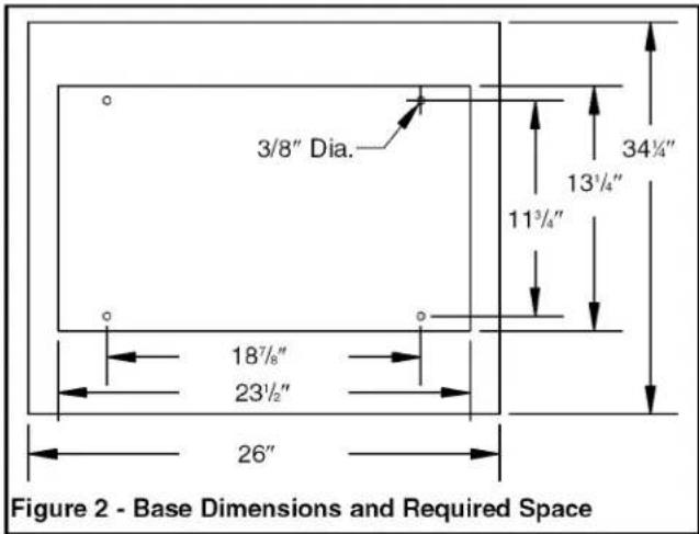
Refer to Figure 2.
- Planer is designed to be portable so it can be moved to job site, but should be mounted to a stable, level bench or table in a place with ample lighting and correct power supply.
- Make sure there is plenty of room for moving the workpiece through the entire cut. There must be enough room that neither the operators or the bystanders will have to stand in line with the wood while using the tool.
- Base of planer has four mounting holes. Mount planer to workbench or tool stand using bolts, flat washers and hex nuts (not supplied).
- Figure 2 shows the base dimensions, mounting holes and required space to allow for table assembly in horizontal position.
- Securely mount planer to work table by bolting it through the holes. Make sure the planer does not rock and the work table is level.
INSTALLATION
POWER SOURCE
WARNING: Do not connect planer to the power source until all assembly steps have been completed.
The motor is designed for operation on the voltage and frequency specified. Normal loads will be handled safely on voltages not more than 10% above or below specified voltage. Running the unit on voltages which are not within range may cause overheating and motor burnout. Heavy loads require that voltage at motor terminals be no less than the voltage specified.
- Power supply to the motor is controlled by a switch with key. Removing the key from switch will lock the unit and prevent unauthorized use.
GROUNDING INSTRUCTIONS
WARNING: Improper connection of equipment grounding conductor can result in the risk of electrical shock. Equipment should be grounded while in use to protect operator from electrical shock.
- Check with a qualified electrician if you do not understand grounding instructions or if you are in doubt as to whether the tool is properly grounded.
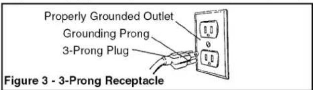
- This tool is equipped with an approved cord and a 3-prong grounding type plug (see Figure 3) for your protection against shock hazards.
- Grounding plug should be plugged directly into a properly installed and grounded 3-prong grounding-type receptacle, as shown (see Figure 3).
- Do not remove or alter grounding prong in any manner. In the event of a malfunction or breakdown, grounding provides a path of least resistance for electrical shock.
WARNING: Do not permit fingers to touch the terminals of plug when installing or removing from outlet.
- Plug must be plugged into matching outlet that is properly installed and grounded in accordance with all local codes and ordinances. Do not modify plug provided. If it will not fit in outlet, have proper outlet installed by a qualified electrician.
- Inspect tool cords periodically, and if damaged, have repaired by an authorized service facility.
- Green (or green and yellow) conductor in cord is the grounding wire. If repair or replacement of the electric cord or plug is necessary, do not connect the green (or green and yellow) wire to a live terminal.
- A 2-prong wall receptacle must be replaced with a properly grounded 3-prong receptacle installed in accordance with National Electric Code and local codes and ordinances.
WARNING: Any receptacle replacement should be performed by a qualified electrician.
A temporary 3-prong to 2-prong grounding adapter (see Figure 4 is available for connecting plugs to a two pole outlet if it is properly grounded.
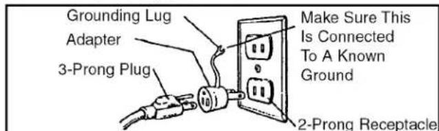
Figure 4 - 2-Prong Receptacle with Adapter
- Do not use a 3-prong to 2-prong grounding adapter unless permitted by local and national codes and ordinances. (A 3-prong to 2-prong grounding adapter is not permitted in Canada.)
Where a 3-prong to 2-prong grounding adapter is permitted, the rigid green tab or terminal on the side of the adapter must be securely connected to a permanent electrical ground such as a properly grounded water pipe, a properly grounded outlet box or a properly grounded wire system. - Many cover plate screws, water pipes and outlet boxes are not properly grounded. To ensure proper ground, grounding means must be tested by a qualified electrician.
EXTENSION CORDS
- The use of any extension cord will cause some drop in voltage and loss of power.
- Wires of the extension cord must be of sufficient size to carry the current and maintain adequate voltage.
- Use the table to determine the minimum wire size (A.W.G.) extension cord.
- Use only 3-wire extension cords having 3-prong grounding type plugs and 3-pole receptacles which accept the tool plug.
- If the extension cord is worn, cut or damaged in any way, replace it immediately.
Extension Cord Length
Wire Size A.W.G.
Up to 25 ft. 14
25 to 50 ft. 12
NOTE: Using extension cords over 50 ft. long is not recommended.
MOTOR
The 120 Volt AC universal motor has the following specifications:
Voltage 120
Amperes....15
Hertz 60
Phase.... Single
Cutterhead RPM 10,000
ELECTRICAL CONNECTIONS
WARNING: Make sure unit is turned off and disconnected from power source before inspecting any wiring.
The motor is assembled with an approved three conductor cord to be used on 120 volts as indicated. The power supply to the motor is controlled by a double pole locking switch.
The power lines are connected directly to the switch. The green ground line must remain securely fastened to the frame to properly protect against electrical shock.
A manual reset overload protector is installed in line with the power supply to the motor. If the planer is overloaded, the protector will break the circuit.
OPERATION
DESCRIPTION
Craftsman 13" planer finishes rough-cut lumber to size and planes soft and hardwoods up to 6" thick and 13" wide. Wood feeds into three-blade cutterhead by rubber infeed/outfeed rollers. Sturdy base construction, granite table and four-post design permits smooth feeding and virtually snipeless planing. Planer comes with enclosed, universal ball bearing, 15 Amp motor with overload protection. Motor has ON/OFF switch with removable key to prevent accidental start-up. Unit features depth-of-cut gauge for convenient set-up, workpiece thickness pre-set gauge with 8 settings for consistent set-up, easy hands-free replacement of blades for safety and minimized downtime, top mounted rollers for workpiece return and built-in carrying handles for portability. Planer takes cuts up to 332'' per pass at 26 feet per minute. Inch height scale has graduations in 116'' increments, and metric height scale has graduations in 1mm increments.
SPECIFICATIONS
Table Size 13" x 9 ^3/4 "
Extension Table Size....14" x 12"
Base Size 23 ^1/8 x 13 ^1/8 "
Workpiece Width (max.) 13"
Workpiece Thickness (max.) 6"
Maximum Depth of Cut 18
Cuts Per Minute 30,000
Feed Rate 26 FPM
Overall Dimensions ..... 25 ^1/2 " W x 34 ^1/5 " D x 24 ^1/4 " H
Weight 94 lbs
Shipping Weight 101 lbs
WARNING: For your own safety, read all of the instructions and precautions before operating tool.
WARNING: Operation of any power tool can result in foreign objects being thrown into eyes which can result in severe eye damage. Always wear safety goggles complying with United States ANSI Z87.1 (shown on package) before commencing power tool operation.
CAUTION: Always observe the following safety precautions:
- Know general power tool safety. Make sure all precautions are understood (see pages 2, 3, 5 and 6).
- Whenever adjusting or replacing any parts on planer, turn switch OFF and remove plug from power source.
- Make sure all guards are properly attached and securely fastened.
• Make sure all moving parts are free from interference.
• Always wear eye protection or face shield.
- Make sure blades are aligned and properly attached to cutterhead.
- Do not plug in planer unless switch is in off position. After turning switch on, allow planer to come to full speed before operating.
- Keep hands clear of all moving parts.
- Do not force cut. Slowing or stalling will overheat motor. Allow automatic feed to function properly.
- Use quality lumber. Blades last longer and cuts are smoother with good quality wood.
- Do not plane material shorter than 15", narrower than 3/4" , wider than 13" or thinner than 1/2" .
- Never make planing cut deeper than 332 ".
- For workpieces longer than 24", use material support stands. See Recommended Accessories, page 13.
- Do not back the work toward the infeed side.
- Take precautions against kickback. Do not permit anyone to stand or cross in line of cutterhead's rotation. Kickback or thrown debris will travel in this direction.
- Turn switch off and disconnect power whenever planer is not in use.
- Replace knives as they become damaged or dull.
- Keep planer maintained. Follow maintenance instructions (see pages 8 -9).
OPERATING CONTROLS
ON/OFF SWITCH
Refer to Figure 5.
The ON/OFF switch is located on the front of the planer motor. To turn the planer ON, move the switch to the up position. To turn the planer OFF, move the switch to the down position.
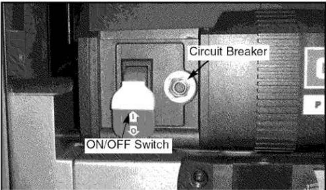
Figure 5 - ON/OFF Switch and Circuit Reset
SWITCH LOCK
Refer to Figure 6.
The planer can be locked from unauthorized use by locking the switch. To lock the switch:
- Turn the switch to OFF position and disconnect planer from power source.
- Pull the key out. The switch cannot be turned on with the key removed.
NOTE: Should the key be removed from the switch at the ON position, the switch can be turned off but cannot be turned on.
- To replace key, slide key into the slot on switch until it snaps.
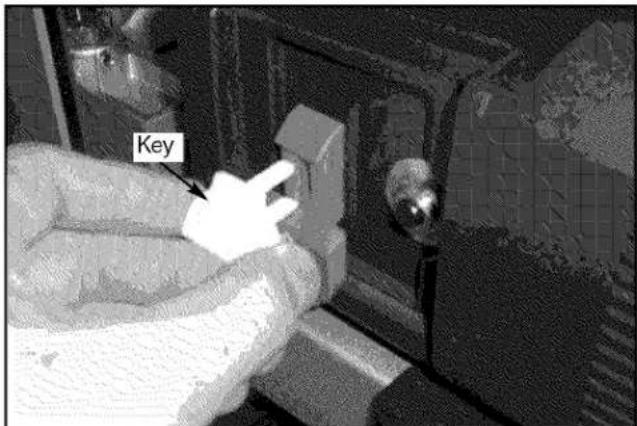
Figure 6 - Switch Lock
CIRCUIT BREAKER
Refer to Figure 5.
The planer is equipped with a motor protection device-circuit breaker. The breaker will automatically shut the planer off when excessive current is consumed.
If the breaker is tripped, turn the planer off and reset the circuit by pressing the button.
CAUTION: Be sure to turn the planer off prior to resetting the circuit breaker to avoid unintentional start-up of the planer.
DEPTH OF CUT
Refer to Figure 12.
Thickness planing refers to the sizing of lumber to a desired thickness while creating a level surface parallel to the opposite side of the board. Board thickness which the planer will produce is indicated by the scale (Key No. 30).
Depth-of-cut is adjusted by raising or lowering the rollercase using handle (Key No. 27).
- Each full rotation of the handle moves the rollercase ^1/15
- Quality of thickness planing depends on the operator's judgement about the depth of cut.
- Depth of cut depends on the width, hardness, dampness, grain direction and grain structure of the wood.
- Maximum thickness of wood which can be removed in one pass is 18 " for planing operations on workpieces up to 6" wide. Workpiece must be positioned away from the center tab on the rollercase to cut 18 ".
- Maximum thickness of wood which can be removed in one pass is 116'' for planing operations on workpiece from 6" up to 13" wide.
CAUTION: A 332 " depth-of-cut on hard, softwood 6-13" wide can be made. However, continuous operation at this set-up can cause premature motor failure.
- For optimum planing performance, the depth of cut should be less than 116 .
- Board should be planed with shallow cuts until the work has a level side. Once a level surface has been created, flip the lumber and create parallel sides.
- Plane alternate sides until the desired thickness is obtained. When half of total depth of cut is taken from each side, the board will have a uniform moisture content and additional drying will not cause it to warp.
- Depth of cut should be shallower when work is wider.
- When planing hardwood, take light cuts or plane the wood in thin widths.
- Make a test cut with a test piece and verify the thickness produced.
- Check accuracy of test cut prior to working on finished product.
DEPTH-OF-CUT GAUGE
Refer to Figure 13.
A spring loaded depth-of-cut gauge (Key No. 23) is attached to front of rollercase. The pointer on depth-of-cut gauge accurately displays the depth-of-cut per pass when workpiece is positioned below the gauge.
Cranking the handle moves the rollercase down and the pointer shows depth-of-cut up to 332 "
Recommended Maximum Depth-Of-Cut:
Hard/Softwood up to 6" wide: .... ^1/8 "
Hard/Softwood 6-13" wide: .... ^3/32 "
CAUTION: A 332 " depth-of-cut on hard, softwood 6-13" wide can be made. However, continuous operation at this set-up can cause premature motor failure.
WORKPIECE THICKNESS PRE-SET GAUGE
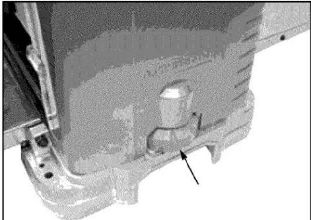
Refer to Figure 7.
An eight position workpiece thickness pre-set control knob is mounted on right side of planer. This knob allows operator to preset the desired finished workpiece thickness. Eight settings are provided: 18 , 14 , 12 , 34 , 1", 114 ", 112 " and 134 ".
Example: Plane a 2" thick workpiece up to 1 ^1/4 ".
- Raise or lower rollercase until it is just above the workpiece.
- Position the workpiece on the planer table below the rollercase.
- Rotate knob until 1 14 " is indicated.
- The planer is now set to stop the rollercase when the workpiece thickness reaches 1^1/4 .
NOTE: To reset for a different depth stop, raise the rollercase by about 2 rotations. Turn knob to desired set-up.
natural_image
Close-up of a mechanical component with a highlighted part and an arrow pointing to a feature (no visible text or symbols)Figure 7 - Workpiece Thickness Pre-set Guage
AVOID DAMAGE TO BLADES
- Thickness planer is a precision woodworking machine and should be used on quality lumber only.
- Do not plane dirty boards; dirt and small stones are abrasive and will wear out blade.
- Remove nails and staples. Use planer to cut wood only.
- Avoid knots. Heavily cross-grained wood makes knots hard. Knots can come loose and jam blade.
CAUTION: Any article that encounters planer blades may be forcibly ejected from planer creating risk of injury.
PREPARE WORK
- Thickness planer works best when lumber has at least one flat surface.
-
Use surface planer or jointer to create a flat surface.
-
Twisted or severely warped boards can jam planer. Rip lumber in half to reduce magnitude of warp.
- Work should be fed into planer in same direction as the grain of the wood. Sometimes grain will change directions in middle of board. In such cases, if possible, cut board in middle before planing so grain direction is correct.
CAUTION: Do not plane board which is less than 15" long; force of cut could split board and cause kickback.
FEEDING WORK
The planer is supplied with planing blades mounted in the cutterhead and infeed and outfeed rollers adjusted to the correct height. Planer feed is automatic; it will vary slightly depending on type of wood.
- Feed rate refers to rate at which lumber travels through planer.
- Align work perpendicular to rollercase so that work feeds through planer straight.
- Raise/lower rollercase to produce the depth of cut desired.
- Stand on side to which the handle is attached.
- Boards longer than 24" should have additional support from free standing material stands.
- Position the workpiece with the face to be planed on top.
- Turn the planer on.
- Rest board end on table and direct board into planer.
- Gently slide workpiece into the infeed side of the planer until the infeed roller begins to advance the workpiece.
- Let go of the workpiece and allow automatic feed to advance the workpiece.
- Do not push/pull on workpiece. Move to the rear and receive planed lumber by grasping it in same manner as it was fed.
CAUTION: To avoid risk of injury due to kickbacks, do not stand directly in line with front or rear of planer.
- Do not grasp any portion of board which has not gone past out-feed roller.
- Repeat this operation on all boards which need to be same thickness.
- Planer has return rollers on top so assistant can pass work back to operator.
NOTE: Assistant must follow same precautions as operator.
- Surface that the planer will produce will be smoother if shallower depth of cut is used.
Avoiding Snipe
- Snipe refers to a depression at either end of board caused by an uneven force on cutterhead when work is entering or leaving planer.
-
Snipe will occur when boards are not supported properly or when only one feed roller is in contact with work at beginning or end of cut.
-
To avoid snipe, gently push the board up while feeding the work until the outfeed roller starts advancing it.
- Move to the rear and receive planed board by gently pushing it up when the infeed roller looses contact with the board.
- When planing more than one board of the same thickness, butt boards together to avoid snipe.
- Snipe is more apparent when deeper cuts are taken.
- Feed work in direction of grain. Work fed against grain will have chipped, splintered edges.
MAINTENANCE
Planer will operate best if kept in good condition and properly adjusted.
CHECK FOR WORN BLADES
- Condition of blades will affect precision of cut. Observe quality of cut which planer produces to check condition of blades.
- Dull blades will tear, rather than sever wood fibers and produce fuzzy appearance.
- Raised grain will occur when dull blades pound on wood that has varying density. Raised edge will also be produced where blades have been nicked.
- Blades on this planer are reversible. Blades should always be reversed or replaced as matched set. Keeping a spare set of blades on hand is recommended.
CHANGING BLADES
Refer to Figures 8-10 page 8.
WARNING: Always turn planer OFF and disconnect from power source before starting any maintenance work.
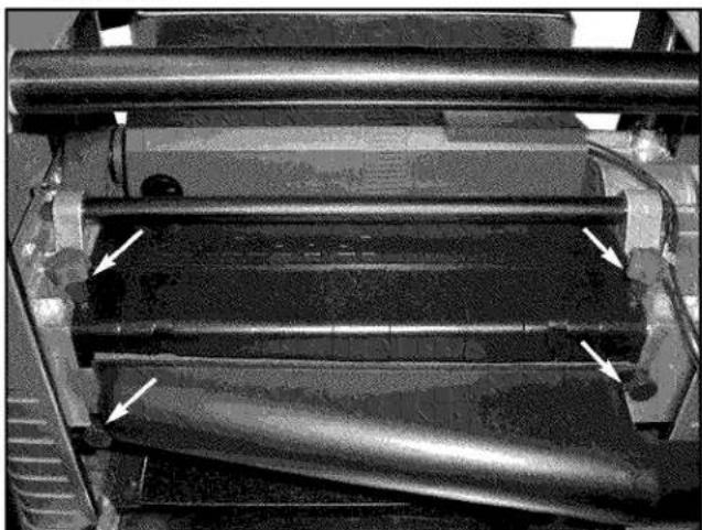
- Loosen and remove thumb screws from dust chute and hood on the rear side of planer. Remove chute and hood.
natural_image
Close-up of industrial machinery components with visible pipes and a curved duct (no text or symbols)Figure 8 - Remove Dust Chute and Hood
- Loosen and remove three screws and belt guard.
- Press cutterhead latch down and carefully rotate belt towards you until cutterhead locks in position.
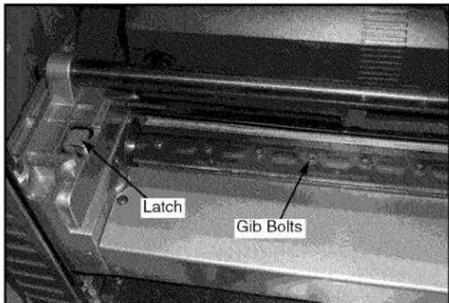
Figure 9 - Remove Gib Bolts
- Loosen, but do not remove, eight screws located on gib. Loosen screws just enough so that gib is loose, allowing blade to be removed.
- Insert the magnetic blade removal tool under the center of the gib.
- Lift the tool up until blade is free of pins and then remove blade.
NOTE: Magnet can be easily disengaged from gib by tilting it to left or right.
CAUTION: Blade edges are extremely sharp. Keep fingers away from blades at all times.
- Blade is located in position by two pins. Carefully lift old blades from cutterhead using magnets. Do not make contact with the blade using fingers. Use magnet only.
- Reverse or replace blade and carefully position it on the two pins using magnet.
- Replace gib and align the holes on the gib with holes on the blade using magnet.
- Secure gib to cutterhead using eight bolts earlier.
- Depress latch to release cutterhead. Release latch when cutterhead can be turned by hand.
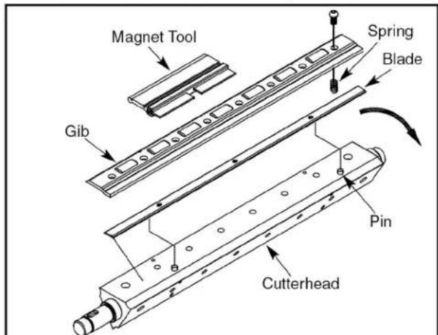
Figure 10 - Remove Blade
- Turn cutterhead by hand until it is stopped by self-engaging latch.
- Remove gib and blade as mentioned earlier.
- Replace with new blade and replace gib and secure it as mentioned earlier.
- Replace dust chute and hood.
BRUSH INSPECTION AND REPLACEMENT
WARNING: Turn planer off and disconnect from power source. Brush life depends on amount of load on motor. Regularly inspect brushes after 100 hours of use. Brushes are located on either side of planer motor.
- Loosen brush cap and carefully remove brush from motor.
NOTE: Brushes are located on both front and rear sides of planer.
- Replace brushes if spring is damaged.
- Replace brushes if carbon is worn.
- Replace brushes and tighten brush caps.
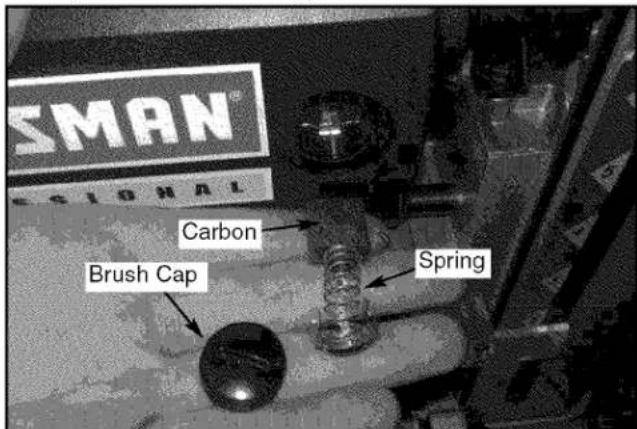
Figure 11 - Replace Brushes
ADJUSTING TABLE LEVEL
Refer to Figures 12 and 13, pages 12 and 14.
The planer will produce uneven depth of cut (tapered cut) if the rollercase (Fig. 13, Key No. 31) is not parallel with the base (Fig. 12, Key No. 34). To restore parallelism of the rollercase with the base:
• Using a test piece, measure the height of the taper.
- Turn planer off and disconnect from power source.
- Fold the front and rear extension tables.
- Lay planer carefully on it's side so that bottom side of the base is exposed.
- Clamp vise plier (not supplied) on the left side of shaft (Fig. 12, Key No. 52) next to the gear (Fig. 12, Key No. 56).
- Remove screw (Fig. 12, Key No. 59) and disengage right gear from the elevation screw gear (Fig. 12, Key No. 56).
- Slowly rotate handle (Fig. 12, Key No. 27) to raise or lower rollercase. Rollercase will move by 0.006" with every turn of the gear by one tooth. Move rollercase tot he required distance to offset the taper.
- Re-engage the right and elevation screw gear and replace retaining ring to secure.
- Release and remove vise plier.
- Set the planer back on its base.
• Make a test cut to verify adjustment.
REPLACING V-BELT
Refer to Figures 12 and 13, pages 12 and 14.
Inadequate tension in the V-belt (Fig. 13, Key No. 53) will cause the belt to slip from the motor pulley (Fig. 13, Key No. 55) or drive pulley (Fig. 13, Key No. 52). Loose belt must be replaced. To replace V-belt:
- Turn planer off and unplug from power source.
- Loosen and remove screws on right cap (Fig. 12, Key No. 28). Remove panel (Fig. 12, Key No. 29).
- Loosen and remove screws (Fig. 13, Key No. 28) on belt guard (Fig. 13, Key No. 27). Remove belt guard.
- Loosen bolt (Fig.13, Key No. 39) to loosen motor assembly.
- Remove old belt by walking the belt from motor and drive pulleys alternatively. Push motor down and pull the belt outward while turning the pulleys at the same time.
- Replace with new belt. Walk the belt on to the pulleys in the reverse manner as when removing the belt.
• Make sure the belt is evenly seated all the way on the motor and drive pulley grooves. - Pry motor upward to apply tension to belt. Secure in position by tightening bolt (Fig. 13, Key No. 39).
- Replace belt guard and screws (Fig. 13, Key Nos. 27 and 28).
- Replace and secure right panel.
LUBRICATION
- Motor and cutterhead bearings are sealed and need no lubrication.
- Gears and elevation screws should be cleaned of debris and greased as needed.
CLEAN PLANER
- Keep planer clean of any wood chips, dust, dirt or debris.
- After 10 hours of operation, the chains and gears should have wood chips, dust and old grease removed.
- Use common automotive bearing grease to lubricate all chains and gears. Be sure all chains and gears have plenty of grease.
- Clean the granite table using a soft, damp cloth. Do not use any waxes, oils or solvents on the table.
TROUBLESHOOTING
| SYMPTOM | POSSIBLE CAUSE(S) | CORRECTIVE ACTION |
| Snipe(gouging at ends of board) | 1.Dull blades2.Inadequate support of long boards3.Uneven force on cutterhead4.Rollercase not level with base5.Lumber not butted properly | 1.Reverse or replace blades per instructions.See “Maintenance”2.Support long boards. See “Avoiding Snipe”3.Gently push board when board is in contact with only one feed roller. See “Avoiding Snipe”4.Adjust rollercaseSee “Adjusting Table Level”5.Butt end to end each piece of stock as boards pass through planer |
| Fuzzy grain | Planing wood with a high moisture content | Remove high moisture content from wood by drying. |
| Torn grain | 1.Too heavy a cut2.Blades cutting against grain3.Dull blades | 1.Review “Depth of Cut”2.Review “Feeding Work”3.Replace blades per instructionsSee “Maintenance” |
| Rough raised grain | 1.Dull blades2.Too heavy a cut3.Moisture content too high | 1.Replace blades per instructionsSee “Maintenance”2.Review “Depth of Cut”3.Dry the wood or use dried wood |
| Uneven depth of cut(side to side) | Rollercase not level with planer base | Rollercase not levelSee “Adjusting Table Level” |
| Rollercase elevation adjusts with difficulty | 1.Gears dirty2.Elevation screws dirty3.Gears, elevation screws worn4.Friction between rollercase and covers5.Rollercase not parallel with planer base | 1.Clean and lubricate gears2.Clean and lubricate elevation screws3.Replace gears, elevation screws4.Clean and lubricate5.Adjust rollercase.See “Adjusting Table Level” |
| Board feeds inside, but stops moving past the outfeed roller | 1.Outfeed roller cannot rotate due to clogging of chips2.Too much pressure on the cutterhead from long workpiece | 1.Clear the clogging from dust collection system. See “Clean Planer”2.Use support stands to support workpiece longer than 24” |
| Board thickness does not match depth of cut scale | Indicator not set correctly | Adjust indicator and tighten securely |
| Chain jumping | 1.Sprockets worn2.Chain worn | 1.Replace sprockets2.Replace chain |
| Planer will not operate | 1.No power to planer2.Motor overload protection tripped3.Defective or loose switch or wiring | 1.Check power source by qualified electrician.2.Turn planer off. Reset motor overload protection. See “Overload Reset”3.Check switch and wiring by qualified electrician |
| Belt slipping | Loose belt | Replace belt, see “Replacing V-Belt” |
NOTES
Model 351.217480
Figure 12 - Replacement Parts Illustration for Base
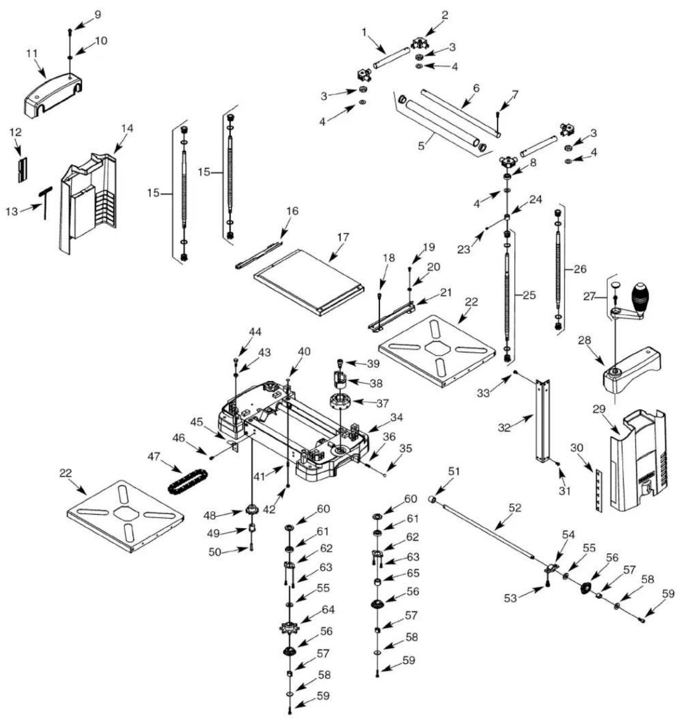
REPLACEMENT PARTS LIST FOR BASE
| KEYNO. | PART NO. | DESCRIPTION | QTY. |
| 1 | 30852.00 | Short Tube | 2 |
| 2 | 30853.00 | Upper Bearing Seat | 4 |
| 3 | 30854.00 | Bushing | 3 |
| 4 | 30855.00 | Washer | 4 |
| 5 | 30856.00 | Roller Assembly | 2 |
| 6 | 30857.00 | Long Tube | 2 |
| 7 | 07541.00 | 4-0.7 x 8mm Socket | 16 |
| Pan Head Screw | |||
| 8 | STD315501 | 6000zz Ball Bearing* | 1 |
| 9 | 30877.00 | 5-0.8 x 16mm Socket | 4 |
| Pan Head Screw | |||
| 10 | 01781.00 | 5mm Flat Washer (N) | 4 |
| 11 | 30858.00 | Left Top Cap | 1 |
| 12 | 30860.00 | Blade Removal Tool | 1 |
| 13 | 30861.00 | 4mm Hex T-wrench | 1 |
| 14 | 30863.00 | Left Side Panel Assembly | 1 |
| 15 | 30864.00 | Elevation Screw Assembly | 2 |
| 16 | 30865.00 | Left Rail Guide | 1 |
| 17 | 30866.00 | Granite Table | 1 |
| 18 | STD870510 | 5-0.8 x 10mm Socket Head Bolt* | 4 |
| 19 | 30748.00 | 6-1.0 x 35mm Socket | 3 |
| Pan Head Screw | |||
| 20 | STD852006 | 6mm Lock Washer* | 3 |
| 21 | 30867.00 | Right Rail Guide | 1 |
| 22 | 30868.00 | Extension Table | 2 |
| 23 | 01210.00 | 5-0.8 x 5mm Set Screw | 1 |
| 24 | 30869.00 | Spacer | 1 |
| 25 | 30870.00 | Elevation Screw Assembly (RF) | 1 |
| 26 | 30871.00 | Elevation Screw Assembly (RR) | 1 |
| 27 | 30872.00 | Crank Handle Assembly | 1 |
| 28 | 30873.00 | Right Top Cap | 1 |
| 29 | 30874.00 | Right Side Panel | 1 |
| 30 | 24764.00 | Scale | 1 |
| 31 | 30876.00 | Screw | 32 |
| 32 | N/A | Support | 4 |
* Standard hardware item available locally
N/A Not available as replacement part
Δ Not Shown
| KEYNO. | PART NO. | DESCRIPTION | QTY. |
| 33 | STD863510 | 5-0.8 x 10mm Pan Head Screw* | 4 |
| 34 | N/A | Base | 1 |
| 35 | 24641.00 | 8mm Steel Ball | 1 |
| 36 | 30878.00 | Spring | 1 |
| 37 | 30879.00 | Depth Stop Base | 1 |
| 38 | 30880.00 | Depth Stop Step | 1 |
| 39 | 30859.00 | Shoulder Bolt | 1 |
| 40 | 30881.00 | Plate | 3 |
| 41 | 05110.00 | 6-1.0 x 20mm Set screw | 3 |
| 42 | 30862.00 | Nut | 3 |
| 43 | STD840610 | 6-1.0mm Hex Nut* | 4 |
| 44 | STD833025 | 6-1.0 x 25mm Hex Head Bolt* | 4 |
| 45 | 30882.00 | Spring Plate | 4 |
| 46 | STD863510 | 5-0.8 x 10mm Pan Head Screw* | 8 |
| 47 | 30883.00 | Chain | 1 |
| 48 | 30884.00 | Idler Gear | 2 |
| 49 | 30885.00 | Idler Gear Shaft | 2 |
| 50 | 05713.00 | 5-0.8 x 25mm SocketPan Head Screw | 2 |
| 51 | 30886.00 | Spacer | 2 |
| 52 | 30887.00 | Shaft | 2 |
| 53 | STD870512 | 5-0.8 x 12mm Socket Head Bolt* | 8 |
| 54 | 30888.00 | Support | 4 |
| 55 | 30889.00 | Spacer | 6 |
| 56 | 30890.00 | Bevel Gear | 8 |
| 57 | 30891.00 | Bushing | 8 |
| 58 | 30892.00 | Spacer | 8 |
| 59 | 07537.00 | 4-0.7 x 10mm Socket Head Bolt | 8 |
| 60 | 30893.00 | Spacer | 4 |
| 61 | STD315501 | 6000zz Ball Bearing* | 4 |
| 62 | 30894.00 | Bearing Retainer | 4 |
| 63 | 06471.00 | 5-0.8 x 12mm SocketPan Head Screw | 8 |
| 64 | 30895.00 | Sprocket | 2 |
| 65 | 30896.00 | Spacer | 2 |
| Recommended Accessories | ||
| Δ | Horizontal Roller Stand | 9-21417 |
| Δ | Three-Roller Stand | 9-22268 |
Model 351.217480
Figure 13 - Replacement Parts Illustration for Rollercase
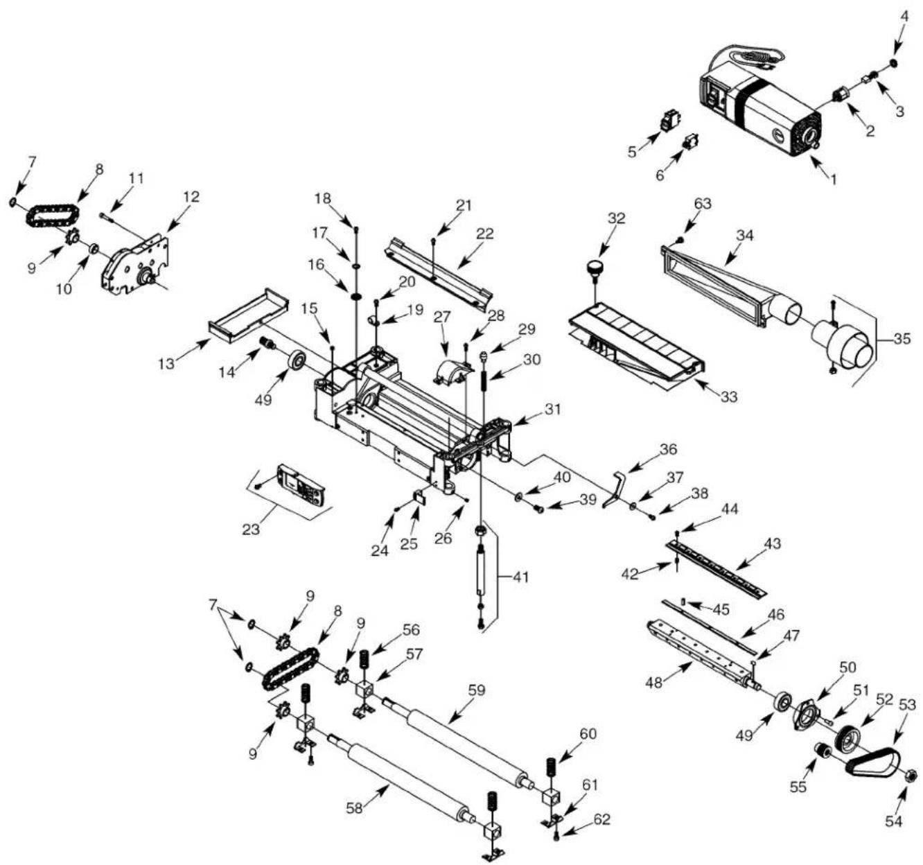
REPLACEMENT PARTS LIST FOR ROLLERCASE
| KEYNO. | PART NO. | DESCRIPTION | QTY. |
| 1 | 30798.00 | Motor Assembly (Inc. Key Nos. 2-6) | 1 |
| 2 | 30799.00 | Brush Holder | 2 |
| 3 | 30800.00 | Brush (Set of 2) | 1 |
| 4 | 30801.00 | Brush Cap | 2 |
| 5 | 30802.00 | Switch w/Key | 1 |
| 6 | 30803.00 | Circuit Breaker | 1 |
| 7 | 00533.00 | 3AMI-15 Retaining Ring | 3 |
| 8 | 30804.00 | Chain | 2 |
| 9 | 30805.00 | Sprocket | 4 |
| 10 | 30806.00 | Spacer | 1 |
| 11 | STD870535 | 5-0.8 x 35mm Socket Head Bolt* | 4 |
| 12 | 30807.00 | Gearbox Assembly | 1 |
| 13 | 30808.00 | Cover | 1 |
| 14 | 30809.00 | Pinion | 1 |
| 15 | 01516.00 | 5-0.8 x 8mm Set Screw | 1 |
| 16 | 01474.00 | 5mm Serrated Washer | 2 |
| 17 | STD852005 | 5mm Lock Washer* | 3 |
| 18 | STD863508 | 5-0.8 x 8mm Pan Head Screw* | 2 |
| 19 | 30810.00 | Cord Clamp | 1 |
| 20 | 16133.00 | 5-0.8 x 10mm Washer Head Screw | 1 |
| 21 | 30811.00 | Screw | 3 |
| 22 | 30812.00 | Chip Deflector | 1 |
| 23 | 30813.00 | Depth of Cut Gauge Assembly | 1 |
| 24 | STD863216 | 3-0.5 x 16mm Pan Head Screw* | 2 |
| 25 | 30814.00 | Depth Indicator | 1 |
| 26 | 04869.00 | 5-0.8 x 6mm Set Screw | 8 |
| 27 | 30815.00 | Belt Guard | 1 |
| 28 | 30712.00 | 4-0.7 x 10mm Washer Head Screw | 3 |
| 29 | 30820.00 | Plunger | 1 |
| 30 | 30821.00 | Spring | 1 |
| 31 | N/A | Rollercase | 1 |
| 32 | 30816.00 | Knob | 2 |
| 33 | 30817.00 | Dust Hood Assembly | 1 |
| KEYNO. | PART NO. | DESCRIPTION | QTY. |
| 34 | 30818.00 | Dust Chute | 1 |
| 35 | 30819.00 | Exhaust Adapter Assembly | 1 |
| 36 | 30822.00 | Cutterhead Lock | 1 |
| 37 | 30823.00 | Spacer | 1 |
| 38 | STD870516 | 5-0.8 x 16mm Socket Head Bolt* | 1 |
| 39 | 02229.00 | 8-1.25 x 20mm SocketPan Head Screw | 1 |
| 40 | STD851008 | 8mm Flat Washer* | 1 |
| 41 | 30824.00 | Depth Stop Assembly | 1 |
| 42 | 30825.00 | Spring | 6 |
| 43 | 30826.00 | Gib | 3 |
| 44 | 09789.00 | 6-1.0 x 16mm SocketPan Head Screw | 24 |
| 45 | 30827.00 | Pin | 6 |
| 46 | 30828.00 | Blade (set of 3) | 1 |
| 47 | 07322.00 | 5 x 5 x 12mm Key | 1 |
| 48 | 30830.00 | Cutterhead | 1 |
| 49 | STD315235 | 6203ZZ Ball Bearing* | 2 |
| 50 | 30831.00 | Bearing Retainer | 1 |
| 51 | STD870510 | 5-0.8 x 10mm Socket Head Bolt* | 3 |
| 52 | 30832.00 | Cutterhead Pulley | 1 |
| 53 | 30833.00 | Drive Belt | 1 |
| 54 | 24799.00 | 16mm Hex Nut (LH) | 1 |
| 55 | 30834.00 | Motor Pulley | 1 |
| 56 | 30835.00 | LH Spring | 2 |
| 57 | 30836.00 | Bearing Block | 4 |
| 58 | 30837.00 | Infeed Roller | 1 |
| 59 | 30838.00 | Outfeed Roller | 1 |
| 60 | 30839.00 | RH Spring | 2 |
| 61 | 30840.00 | Retaining Plate | 4 |
| 62 | 30841.00 | Screw | 8 |
| 63 | 30842.00 | Thumbscrew | 2 |
| 30783.00 | Operator's Manual | 1 |
* Standard hardware item available locally
N/A Not available as replacement part
Δ Not Shown
CEPILLADORA DE ESPESOR DE 13"
Modelo No.
351.217480
Sears, Roebuck and Co., Hoffman Estates, IL 60179
REGLAS DE SEGURIDAD
natural_image
Close-up of a mechanical component with a curved pipe fitting and an arrow pointing to a feature (no visible text or symbols)natural_image
Close-up of industrial machinery components with visible pipes and tools (no text or symbols)Get it fixed, at your home or ours!
Your Home
For expert troubleshooting and home solutions advice:

www.managemyhome.com
For repair – in your home – of all major brand appliances, lawn and garden equipment, or heating and cooling systems, no matter who made it, no matter who sold it!
For the replacement parts, accessories and owner's manuals that you need to do-it-yourself.
For Sears professional installation of home appliances and items like garage door openers and water heaters.
1-800-4-MY-HOME ^® (1-800-469-4663)
Call anytime, day or night (U.S.A. and Canada)
www.sears.com www.sears.ca
Our Home
For repair of carry-in items like vacuums, lawn equipment, and electronics, call anytime for the location of your nearest
Sears Parts & Repair Service Center
1-800-488-1222 (U.S.A.)
www.sears.com
1-800-469-4663 (Canada)
www.sears.ca
To purchase a protection agreement on a product serviced by Sears:
1-800-827-6655 (U.S.A.)
1-800-361-6665 (Canada)
- THICKNESS PLANER
- TABLE OF CONTENTS
- WARRANTY
- ONE-YEAR FULL WARRANTY ON CRAFTSMAN PROFESSIONAL TOOL
- SAFETY RULES
- BE PREPARED FOR JOB
- PREPARE WORK AREA FOR JOB
- TOOL SHOULD BE MAINTAINED
- KNOW HOW TO USE TOOL
- UNPACKING
- ASSEMBLY
- INSTALL HANDLE
- ATTACH DUST CHUTE
- MOUNT PLANER TO WORK SURFACE
- INSTALLATION
- POWER SOURCE
- GROUNDING INSTRUCTIONS
- EXTENSION CORDS
- Extension Cord Length
- MOTOR
- ELECTRICAL CONNECTIONS
- OPERATION
- DESCRIPTION
- SPECIFICATIONS
- OPERATING CONTROLS
- ON/OFF SWITCH
- SWITCH LOCK
- CIRCUIT BREAKER
- DEPTH OF CUT
- DEPTH-OF-CUT GAUGE
- Recommended Maximum Depth-Of-Cut:
- WORKPIECE THICKNESS PRE-SET GAUGE
- AVOID DAMAGE TO BLADES
- PREPARE WORK
- FEEDING WORK
- Avoiding Snipe
- MAINTENANCE
- CHECK FOR WORN BLADES
- CHANGING BLADES
- BRUSH INSPECTION AND REPLACEMENT
- ADJUSTING TABLE LEVEL
- REPLACING V-BELT
- LUBRICATION
- CLEAN PLANER
- Model 351.217480
- CEPILLADORA DE ESPESOR DE 13"
- REGLAS DE SEGURIDAD
- Get it fixed, at your home or ours!
- Your Home
- Our Home
- Sears Parts & Repair Service Center
Brand : Craftsman
Model : 351.217480
Category : Drill