
917.271531 - Drill Craftsman - Free user manual and instructions
Find the device manual for free 917.271531 Craftsman in PDF.


| Product Type | Riding Lawn Mower / Tractor |
| Model Number | 917.271531 |
| Engine | Briggs & Stratton 287707, 14 HP (estimated) |
| Fuel Capacity | 1.25 gallons (unleaded regular) |
| Oil Capacity | 3.0 pints (SAE 30 above 32°F, SAE 5W-30 below) |
| Spark Plug | Champion RC12YC (gap 0.030") |
| Cutting Deck Width | 42 inches |
| Cutting Height Range | 1.5 to 4 inches |
| Ground Speeds (Forward) | 1st: 1.1 mph, 2nd: 1.4 mph, 3rd: 2.2 mph, 4th: 3.4 mph, 5th: 4.3 mph, 6th: 5.5 mph |
| Ground Speed (Reverse) | 1.7 mph |
| Transmission | 6-speed gear drive |
| Steering | Manual sector gear |
| Brake | Adjustable mechanical disc brake |
| Tire Pressure (Front) | 14 PSI |
| Tire Pressure (Rear) | 12 PSI |
| Battery | 12V, 25 Ah, 190 CCA, Group U1R |
| Charging System | 3 amps (battery), 5 amps (headlights) |
| Blade Bolt Torque | 27-35 ft-lbs |
| Safety Systems | Operator presence sensing, parking brake interlock, blade brake |
| Warranty | 2 years limited on parts, 90 days on battery |
Frequently Asked Questions - 917.271531 Craftsman
User questions about 917.271531 Craftsman
0 question about this device. Answer the ones you know or ask your own.
Ask a new question about this device
Download the instructions for your Drill in PDF format for free! Find your manual 917.271531 - Craftsman and take your electronic device back in hand. On this page are published all the documents necessary for the use of your device. 917.271531 by Craftsman.
USER MANUAL 917.271531 Craftsman
natural_image
Side profile of a vintage off-road vehicle with steering wheel and large wheels (no text or symbols visible)- Safety
- Assembly
• Operation - Maintenance
- Repair Parts

This product has a low emission engine which operates differently from previously built engines. Before you start the engine, read and understand this Owner's Manual.
CAUTION:
Read and follow all Safety
Rules and Instructions before operating this equipment.
For answers to your questions
about this product, Call:
1-800-659-5917
Sears Craftsman Help Line
5 am - 5 pm, Mon - Sat
Sears, Roebuck and Co., Hoffman Estates, II 60179
Visit our Craftsman website:www.sears.com/craftsman
TABLE OF CONTENTS
Warranty 2 Safety Rules 3
Product Specifications 6
Assembly 8
Operation 11
Maintenance Schedule 17
Maintenance....17
Service and Adjustments....21
Storage 27
Troubleshooting 28
Repair Parts 32
Parts Ordering .... Back Cover
WARRANTY
LIMITED TWO YEAR WARRANTY ON CRAFTSMAN RIDING EQUIPMENT PARTS For two (2) years from the date of purchase, if this Craftsman Riding Equipment is maintained, lubricated and tuned up according to the instructions in the owner's manual, Sears will repair or replace, free of charge, any parts found to be defective in material or workmanship. Warranty service is available free of charge by returning your Craftsman riding equipment to your nearest Sears Service Center. In-home warranty service is available but a trip charge will apply. This warranty applies only while this product is in the United States.
This Warranty does not cover:
- Expendable items which become worn during normal use, such as blades, spark plugs, air cleaners, belts and oil filters.
- Tire replacement or repair caused by punctures from outside objects, such as nails, thorns, stumps, or glass.
- Repairs necessary because of operator abuse, including but not limited to, damage caused by towing objects beyond the capability of the riding equipment, impacting objects that bend the frame or crankshaft, or over speeding the engine.
- Repairs necessary because of operator negligence, including but not limited to, electrical and mechanical damage caused by improper storage, failure to use the proper grade and amount of engine oil, failure to keep the deck clear of flammable debris, or the failure to maintain the equipment according to the instructions contained in the owner's manual.
- Engine (fuel system) cleaning or repairs caused by fuel determined to be contaminated or oxidized (stale). In general, fuel should be used within thirty (30) days of its purchase date.
- Riding equipment used for commercial or rental purposes. A product is "used for commercial purpose" if is used for any purpose other than single family household dwellings or in usage where profit is made.
LIMITED 90 DAY WARRANTY ON BATTERY
For ninety (90) days from date of purchase, if any battery included with this riding equipment proves defective in material or workmanship and our testing determines the battery will not hold a charge, Sears will replace the battery at no charge. Warranty service is available free of charge by returning your Craftsman riding equipment to your nearest Sears Service Center. In-home warranty service is available but a trip charge will apply. This warranty applies only while this product is in the United States.
TO LOCATE THE NEAREST SEARS SERVICE CENTER OR TO SCHEDULE IN-HOME WARRANTY SERVICE, SIMPLY CONTACT SEARS AT 1-800-4-MY-HOME
This Warranty gives you specific legal rights, and you may also have other rights which may vary from state to state.
Sears, Roebuck and Co., D/817 WA, Hoffman Estates, IL 60179
SAFETY RULES
IMPORTANT: This cutting machine is capable of amputating hands and feet and throwing objects. Failure to observe the following safety instructions could result in serious injury or death.
I. GENERAL OPERATION
- Read, understand, and follow all instructions in the manual and on the machine before starting.
- Only allow responsible adults, who are familiar with the instructions, to operate the machine.
- Clear the area of objects such as rocks, toys, wire, etc., which could be picked up and thrown by the blade.
- Be sure the area is clear of other people before mowing. Stop machine if anyone enters the area.
- Never carry passengers.
- Do not mow in reverse unless absolutely necessary. Always look down and behind before and while backing.
- Be aware of the mower discharge direction and do not point it at anyone. Do not operate the mower without either the entire grass catcher or the guard in place.
- Slow down before turning.
- Never leave a running machine unattended. Always turn off blades, set parking brake, stop engine, and remove keys before dismounting.
• Turn off blades when not mowing. - Stop engine before removing grass catcher or unclogging chute.
- Mow only in daylight or good artificial light.
- Do not operate the machine while under the influence of alcohol or drugs.
- Watch for traffic when operating near or crossing roadways.
- Use extra care when loading or unloading the machine into a trailer or truck.
- Data indicates that operators, age 60 years and above, are involved in a large percentage of riding mower-related injuries. These operators should evaluate their ability to operate the riding mower safely enough to protect themselves and others from serious injury.
- Keep machine free of grass, leaves or other debris build-up which can touch hot exhaust / engine parts and burn. Do not allow the mower deck to plow leaves or other debris which can cause build-up to occur. Clean any oil or fuel spillage before operating or storing the machine. Allow machine to cool before storage.
II. SLOPE OPERATION
Slopes are a major factor related to loss-of-control and tipover accidents, which can result in severe injury or death. All slopes require extra caution. If you cannot back up the slope or if you feel uneasy on it, do not mow it.
DO:
- Mow up and down slopes, not across.
- Remove obstacles such as rocks, tree limbs, etc.
- Watch for holes, nuts, or bumps. Uneven terrain could overturn the machine. Tall grass can hide obstacles.
- Use slow speed. Choose a low gear so that you will not have to stop or shift while on the slope.
- Follow the manufacturer's recommendations for wheel weights or counterweights to improve stability.
- Use extra care with grass catchers or other attachments. These can change the stability of the machine.
- Keep all movement on the slopes slow and gradual. Do not make sudden changes in speed or direction.
- Avoid starting or stopping on a slope. If tires lose traction, disengage the blades and proceed slowly straight down the slope.
- Do not turn on slopes unless necessary, and then, turn slowly and gradually downhill, if possible.
- Do not mow near drop-offs, ditches, or embankments. The mower could suddenly turn over if a wheel is over the edge of a cliff or ditch, or if an edge caves in.
- Do not mow on wet grass. Reduced traction could cause sliding.
- Do not try to stabilize the machine by putting your foot on the ground.
- Do not use grass catcher on steep slopes.
DO NOT:
SAFETY RULES
III. CHILDREN
Tragic accidents can occur if the operator is not alert to the presence of children. Children are often attracted to the machine and the mowing activity. Never assume that children will remain where you last saw them.
- Keep children out of the mowing area and under the watchful care of another responsible adult.
- Be alert and turn machine off if children enter the area.
- Before and when backing, look behind and down for small children.
- Never carry children. They may fall off and be seriously injured or interfere with safe machine operation.
- Never allow children to operate the machine.
- Use extra care when approaching blind corners, shrubs, trees, or other objects that may obscure vision.
IV. SERVICE
- Use extra care in handling gasoline and other fuels. They are flammable and vapors are explosive.
- Use only an approved container. - Never remove gas cap or add fuel with the engine running. Allow engine to cool before refueling. Do not smoke.
- Never refuel the machine indoors.
- Never store the machine or fuel container inside where there is an open flame, such as a water heater.
- Never run a machine inside a closed area.
- Keep nuts and bolts, especially blade attachment bolts, tight and keep equipment in good condition.
- Never tamper with safety devices. Check their proper operation regularly.
- Keep machine free of grass, leaves, or other debris build-up. Clean oil or fuel spillage. Allow machine to cool before storing.
- Stop and inspect the equipment if you strike an object. Repair, if necessary, before restarting.
- Never make adjustments or repairs with the engine running.
- Grass catcher components are subject to wear, damage, and deterioration, which could expose moving parts or allow objects to be thrown. Frequently check components and replace with manufacturer's recommended parts, when necessary.
- Mower blades are sharp and can cut. Wrap the blade(s) or wear gloves, and use extra caution when servicing them.
- Check brake operation frequently. Adjust and service as required.

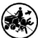

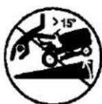

- Be sure the area is clear of other people before mowing. Stop machine if anyone enters the area.
- Never carry passengers or children even with the blades off.
- Do not mow in reverse unless absolutely necessary. Always look down and behind before and while backing.
- Never carry children. They may fall off and be seriously injured or interfere with safe machine operation.
-
Keep children out of the mowing area and under the watchful care of another responsible adult.
-
Be alert and turn machine off if children enter the area.
• Before and when backing, look behind and down for small children. - Mow up and down slopes (15° Max), not across.
- Remove obstacles such as rocks, tree limbs, etc.
- Watch for holes, nuts, or bumps. Uneven terrain could overturn the machine. Tall grass can hide obstacles.
SAFETY RULES
- Use slow speed. Choose a low gear so that you will not have to stop or shift while on the slope.
- Avoid starting or stopping on a slope. If tires lose traction, disengage the blades and proceed slowly straight down the slope.
- If machine stops while going uphill, disengage blades, shift into reverse and back down slowly.
- Do not turn on slopes unless necessary, and then, turn slowly and gradually downhill, if possible.
Look for this symbol to point out important safety precautions. It means CAUTION!!! BECOME ALERT!!! YOUR SAFETY IS INVOLVED.
A CAUTION: In order to prevent accidental starting when setting up, transporting, adjusting or making repairs, always disconnect spark plug wire and place wire where it cannot contact spark plug.
A CAUTION: Do not coast down a hill in neutral, you may lose control of the tractor.
A CAUTION: Tow only the attachments that are recommended by and comply with specifications of the manufacturer of your tractor. Use common sense when towing. Operate only at the lowest possible speed when on a slope. Too heavy of a load, while on a slope, is dangerous. Tires can lose traction with the ground and cause you to lose control of your tractor.
WARNING: Engine exhaust, some of its constituents, and certain vehicle components contain or emit chemicals known to the State of California to cause cancer and birth defects or other reproductive harm.
WARNING: Battery posts, terminals and related accessories contain lead and lead compounds, chemicals known to the State of California to cause cancer and birth defects or other reproductive harm. Wash hands after handling.
PRODUCT SPECIFICATIONS
| GASOLINECAPACITYAND TYPE: | 1.25 GALLONSUNLEADEDREGULAR | |
| OIL TYPE(API-SF-SJ): | SAE 30(ABOVE 32°F)SAE 5W-30(Below 32°F) | |
| OIL CAPACITY: | 3.0 PINTS | |
| SPARK PLUG:(GAP: .030") | CHAMPIONRC12YC | |
| GROUND SPEED(MPH): | FORWARD:1ST 1.12ND 1.43RD 2.24TH 3.45TH 4.36TH 5.5REVERSE: 1.7 | |
| TIREPRESSURE: | FRONT: 14 PSIREAR: 12 PSI | |
| CHARGINGSYSTEM: | 3 AMPS BATTERY5 AMPS HEADLIGHTS | |
| BATTERY: | AMP/HR: 25MIN. CCA: 190CASE SIZE:U1R | |
| BLADE BOLTTORQUE: | 27-35 FT. LBSTORQUE: | |
CONGRATULATIONS on your purchase of a new tractor. It has been designed, engineered and manufactured to give you the best possible dependability and performance.
Should you experience any problem you cannot easily remedy, please contact a Sears or other qualified service center. We have competent, well-trained technicians and the proper tools to service or repair this tractor.
Please read and retain this manual. The instructions will enable you to assemble and maintain your tractor properly. Always observe the "SAFETY RULES".
REPAIR AGREEMENT
A Repair Agreement is available on this product. Contact your nearest Sears store for details.
CUSTOMER RESPONSIBILITIES
- Read and observe the safety rules.
- Follow a regular schedule in maintaining, caring for and using your tractor.
- Follow the instructions under "Maintenance" and "Storage" sections of this owner's manual.
WARNING: This tractor is equipped with an internal combustion engine and should not be used on or near any unimproved forest-covered, brush-covered or grass-covered land unless the engine's exhaust system is equipped with a spark arrester meeting applicable local or state laws (if any). If a spark arrester is used, it should be maintained in effective working order by the operator. In the state of California the above is required by law (Section 4442 of the California Public Resources Code). Other states may have similar laws. Federal laws apply on federal lands. A spark arrester for the muffler is available through your nearest Sears service center (See REPAIR PARTS section of this manual).
UNASSEMBLED PARTS
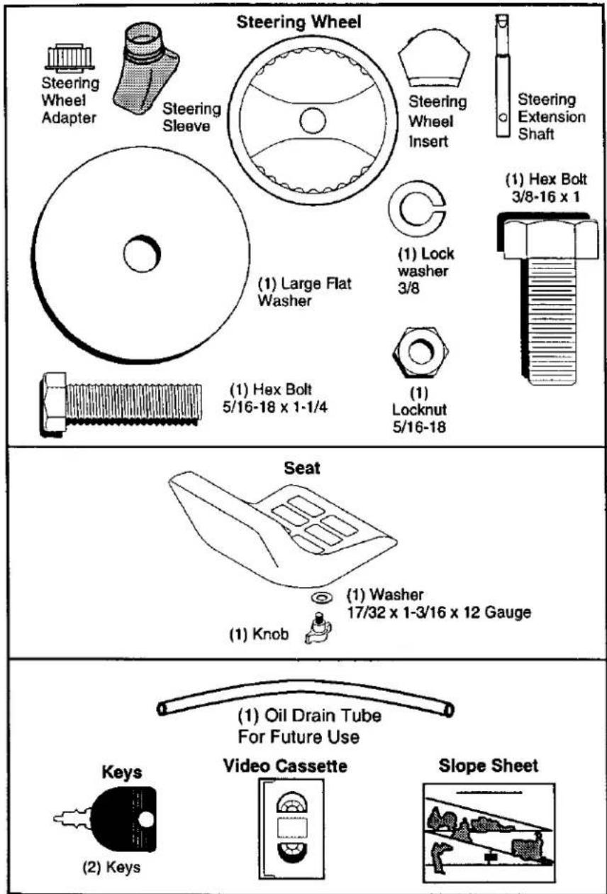
ASSEMBLY
Your new tractor has been assembled at the factory with exception of those parts left unassembled for shipping purposes. To ensure safe and proper operation of your tractor all parts and hardware you assemble must be tightened securely. Use the correct tools as necessary to insure proper tightness. Review the video cassette before you begin.
TOOLS REQUIRED FOR ASSEMBLY
A socket wrench set will make assembly easier. Standard wrench sizes you need are listed below.
(1) 9/16" wrench (1) Pliers
(1) 1/2" wrench (1) Utility knife
(1) Tire pressure gauge
When right or left hand is mentioned in this manual, it means, from your point of view, when you are in the operating position (seated behind the steering wheel).
TO REMOVE TRACTOR FROM CARTON
UNPACK CARTON
- Remove all accessible loose parts and parts cartons from carton.
- Cut, from top to bottom, along lines on all four corners of carton, and lay panels flat.
- Check for any additional loose parts or cartons and remove.
BEFORE REMOVING TRACTOR FROM SKID
ATTACH STEERING WHEEL
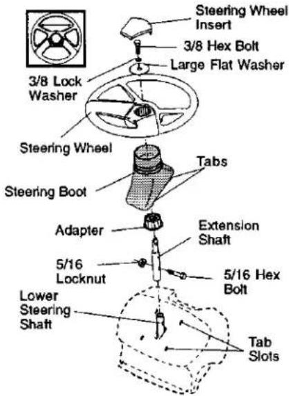
ASSEMBLE EXTENSION SHAFT AND BOOT
- Slide extension shaft onto lower steering shaft. Align mounting holes in extension and lower shafts and install 5/16 hex bolt and locknut. Tighten securely.
IMPORTANT: Tighten bolt and nut securely to 18-22 ft. lbs torque.
- Place tabs of steering boot over tab slots in dash and push down to secure.
INSTALL STEERING WHEEL
- Position front wheels of the tractor so they are pointing straight forward.
- Remove steering wheel adapter from steering wheel and slide adapter onto steering shaft extension.
-
Position steering wheel so cross bars are horizontal (left to right) and slide inside boot and onto adapter.
-
Assemble large flat washer, 3/8 lock washer, 3/8 hex bolt and tighten securely.
- Snap steering wheel insert into center of steering wheel.
- Remove protective materials from tractor hood and grill.
IMPORTANT: Check for and remove any staples in skid that may puncture tires where tractor is to roll off skid.
HOW TO SET UP YOUR TRACTOR CHECK BATTERY
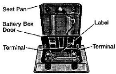
- Lift seat pan to raised position and open battery box door.
NOTE: If this battery is put into service after month and year indicated on label (label located between terminals) charge battery for minimum of one hour at 6-10 amps. (See "BATTERY" in Maintenance section of this manual for charging instructions).
INSTALL SEAT
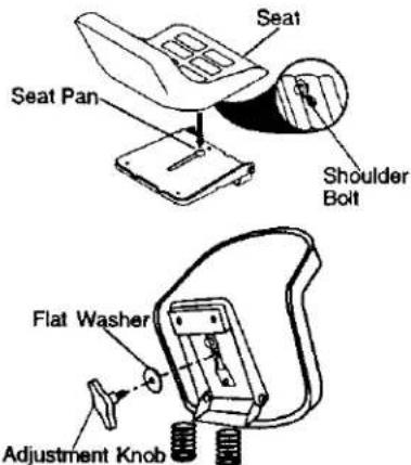
Adjust seat before tightening adjustment knob.
- Remove adjustment knob and flat washer securing seat to cardboard packing and set aside for assembly of seat to tractor.
- Pivot seat upward and remove from the cardboard packing. Remove the cardboard packing and discard.
- Place seat on seat pan so head of shoulder bolt is positioned over large slotted hole in pan.
- Push down on seat to engage shoulder bolt in slot and pull seat towards rear of tractor.
- Pivot seat and pan forward and assemble adjustment knob and flat washer loosely. Do not tighten.
- Lower seat into operating position and sit in seat.
- Slide seat until a comfortable position is reached which allows you to press clutch/brake pedal all the way down.
- Get off seat without moving its adjusted position.
- Raise seat and tighten adjustment knob securely.
NOTE: You may now roll or drive your tractor off the skid. Follow the appropriate instruction below to remove the tractor from the skid.
TO ROLL TRACTOR OFF SKID (See Operation section for location and function of controls)
- Press lift lever plunger and raise attachment lift lever to its highest position.
- Release parking brake by depressing clutch/brake pedal.
- Place gearshift lever in neutral (N) position.
- Roll tractor forward off skid.
- Remove banding holding deflector shield up against tractor.
TO DRIVETRACTOR OFF SKID (See Operation section for location and function of controls)
WARNING: Before starting, read, understand and follow all instructions in the Operation section of this manual. Be sure tractor is in a well-ventilated area. Be sure the area in front of tractor is clear of other people and objects.
- Be sure all the above assembly steps have been completed.
- Check engine oil level and fill fuel tank with gasoline.
- Sit on seat in operating position, depress clutch/brake pedal and set the parking brake.
- Place gear shift lever in neutral (N) position.
- Press lift lever plunger and raise attachment lift lever to its highest position.
- Start the engine. After engine has started, move throttle control to idle position.
- Depress clutch/brake pedal into full "BRAKE" position and hold. Move gearshift lever to 1st gear.
- Slowly release clutch/brake pedal and slowly drive tractor off skid.
- Apply brake to stop tractor, set parking brake and place gearshift lever in neutral position.
- Turn ignition key to "OFF" position. Continue with the instructions that follow.
CHECK TIRE PRESSURE
The tires on your tractor were overinflated at the factory for shipping purposes. Correct tire pressure is important for best cutting performance.
- Reduce tire pressure to PSI shown in "PRODUCT SPECIFICATIONS" section of this manual.
CHECK DECK LEVELNESS
For best cutting results, mower housing should be properly leveled. See "TO LEVEL MOWER HOUSING" in the Service and Adjustments section of this manual.
CHECK FOR PROPER POSITION OF ALL BELTS
See the figures that are shown for replacing motion and mower blade drive belts in the Service and Adjustments section of this manual. Verify that the belts are routed correctly.
CHECK BRAKE SYSTEM
After you learn how to operate your tractor, check to see that the brake is properly adjusted. See "TO ADJUST BRAKE" in the Service and Adjustments section of this manual.
√ CHECKLIST
Before you operate and enjoy your new tractor, we wish to assure that you receive the best performance and satisfaction from this Quality Product.
Please review the following checklist:
√ All assembly instructions have been completed.
√ No remaining loose parts in carton.
√ Battery is properly prepared and charged. (Minimum 1 hour at 6 amps).
√ Seat is adjusted comfortably and tightened securely.
√ All tires are properly inflated. (For shipping purposes, the tires were overinflated at the factory).
√ Be sure mower deck is properly leveled side-to-side/front-to-rear for best cutting results. (Tires must be properly inflated for leveling).
√ Check mower and drive belts. Be sure they are routed properly around pulleys and inside all belt keepers.
√ Check wiring. See that all connections are still secure and wires are properly clamped.
While learning how to use your tractor, pay extra attention to the following important items:
√Engine oil is at proper level.
√ Fuel tank is filled with fresh, clean, regular unleaded gasoline.
√ Become familiar with all controls - their location and function. Operate them before you start the engine.
√ Be sure brake system is in safe operating condition.
OPERATION
These symbols may appear on your tractor or in literature supplied with the product. Learn and understand their meaning.
BATTERY

CAUTION OR WARNING

REVERSE

FORWARD

FAST

SLOW

ENGINE ON

ENGINE OFF
OIL PRESSURE
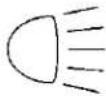
LIGHTS ON

OVER TEMP
LIGHT


FUEL
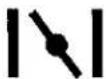
CHOKE

MOWER HEIGHT

SLOPE HAZARDS
(SEE SAFETY RULES SECTION)

DANGER, KEEP HANDS AND FEET AWAY
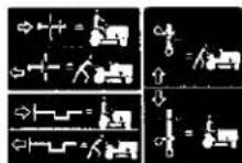
FREE WHEEL
(Automatic Models only)
KNOW YOUR TRACTOR
READ THIS OWNER'S MANUAL AND SAFETY RULES BEFORE OPERATING YOUR TRACTOR
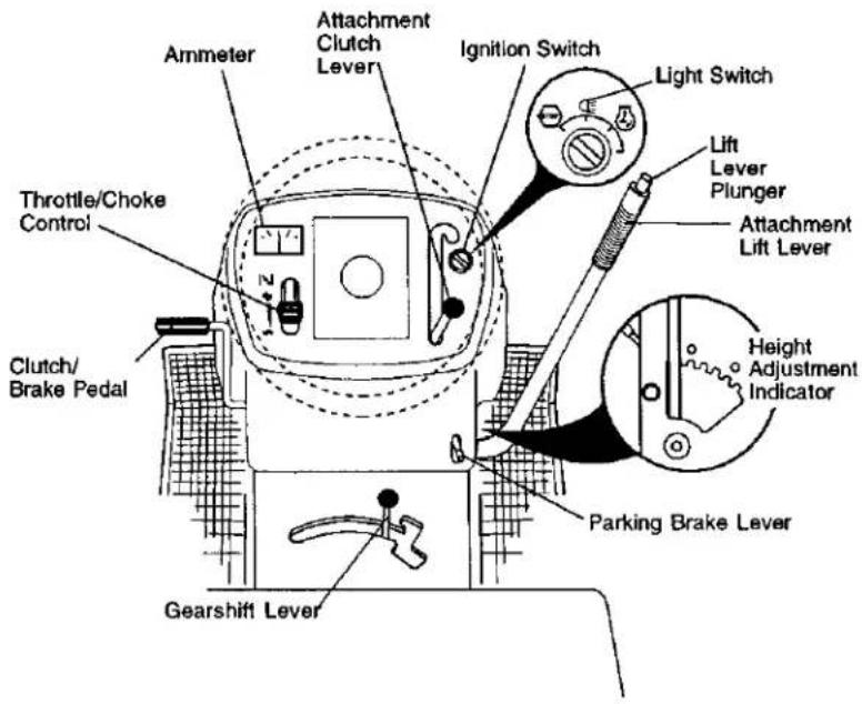
Compare the illustrations with your tractor to familiarize yourself with the locations of various controls and adjustments. Save this manual for future reference.
Our tractors conform to the safety standards of the American National Standards Institute.
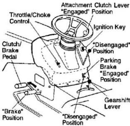
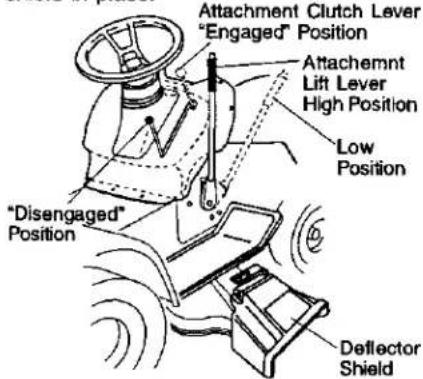
ATTACHMENT CLUTCH LEVER - Used to engage the mower blades, or other attachments mounted to your tractor. ATTACHMENT LIFT LEVER - Used to raise, lower, and adjust the mower deck or other attachments mounted to your tractor.
CLUTCH/BRAKE PEDAL - Used for declutching and braking the tractor and starting the engine. GEARSHIFT LEVER - Selects the speed and direction of tractor.
IGNITION SWITCH - Used for starting and stopping the engine.
LIFT LEVER PLUNGER - Used to release attachment lift lever when changing its position.
LIGHT SWITCH - Turns the headlights on and off.
PARKING BRAKE LEVER - Locks clutch/brake pedal into the brake position.
THROTTLE/CHOKE CONTROL - Used for starting and controlling engine speed.
AMMETER - Indicates battery charging (+) or discharging (-).

The operation of any tractor can result in foreign objects thrown into the eyes, which can result in severe eye damage. Always wear safety glasses or eye shields while operating your tractor or performing any adjustments or repairs. We recommend a wide vision safety mask over spectacles or standard safety glasses.
HOW TO USE YOUR TRACTOR TO SET PARKING BRAKE
Your tractor is equipped with an operator presence sensing switch. When engine is running, any attempt by the operator to leave the seat without first setting the parking brake will shut off the engine.
- Depress clutch/brake pedal into full "BRAKE" position and hold.
- Place parking brake lever in "ENGAGED" position and release pressure from clutch/brake pedal. Pedal should remain in "BRAKE" position. Make sure parking brake will hold tractor secure.
STOPPING
MOWER BLADES -
- To stop mower blades, move attachment clutch lever to "DISENGAGED" position.
GROUND DRIVE -
• To stop ground drive, depress clutch/brake pedal into full "BRAKE" position.
- Move gearshift lever to neutral (N) position.
ENGINE -
- Move throttle control to slow position. NOTE: Failure to move throttle control to slow position and allowing engine to idle before stopping may cause engine to "backfire".
- Turn ignition key to "OFF" position and remove key. Always remove key when leaving tractor to prevent unauthorized use.
- Never use choke to stop engine.
IMPORTANT: Leaving the ignition switch in any position other than "OFF" will cause the battery to be discharged, (dead).
NOTE: Under certain conditions when tractor is standing idle with the engine running, hot engine exhaust gases may cause "browning" of grass. To eliminate this possibility, always stop engine when stopping tractor on grass areas.
A CAUTION: Always stop tractor completely, as described above, before leaving the operator's position; to empty grass catcher, etc.
TO USE THROTTLE CONTROL
Always operate engine at full throttle.
- Operating engine at less than full throttle reduces the battery charging rate.
• Full throttle offers the best bagging and mower performance.
TO MOVE FORWARD AND BACK- WARD
The direction and speed of movement is controlled by the gearshift lever.
- Start tractor with clutch/brake pedal depressed and gearshift lever in neutral (N) position.
- Move gearshift lever to desired position.
- Slowly release clutch/brake pedal to start movement.
IMPORTANT: Bring tractor to a complete stop before shifting or changing gears.
Failure to do so will shorten the useful life of your transaxle.
TO ADJUST MOWER CUTTING HEIGHT
The position of the attachment lift lever determines the cutting height.
- Grasp lift lever.
- Press plunger with thumb and move lever to desired position.
The cutting height range is approximately 1-1/2 to 4". The heights are measured from the ground to the blade tip with the engine not running. These heights are approximate and may vary depending upon soil conditions, height of grass and types of grass being mowed.
- The average lawn should be cut to approximately 2-1/2 inches during the cool season and to over 3 inches during hot months. For healthier and better looking lawns, now often and after moderate growth.
- For best cutting performance, grass over 6 inches in height should be mowed twice. Make the first cut relatively high; the second to desired height.
TO OPERATE MOWER
Your tractor is equipped with an operator presence sensing switch. Any attempt by the operator to leave the seat with the engine running and the attachment clutch engaged will shut off the engine.
- Select desired height of cut.
- Start mower blades by engaging attachment clutch control.
To stop mower blades - disengage attachment clutch control.
CAUTION: Do not operate the mower without either the entire grass catcher, on mowers so equipped, or the deflector shield in place.
TO OPERATE ON HILLS
⚠️CAUTION: Do not drive up or down hills with slopes greater than 15° and do not drive across any slope.
- Choose the slowest speed before starting up or down hills.
-
Avoid stopping or changing speed on hills.
-
If slowing is necessary, move throttle control lever to slower position.
- If stopping is absolutely necessary, push clutch/brake pedal quickly to brake position and engage parking brake.
- Move gearshift lever to 1st gear. Be sure you have allowed room for tractor to roll slightly as you restart movement.
• To restart movement, slowly release parking brake and clutch/brake pedal.
• Make all turns slowly.
TO TRANSPORT
- Raise attachment lift to highest position with attachment lift control.
- When pushing or towing your tractor, be sure gearshift lever is in neutral (N) position.
- Do not push or tow tractor at more than five (5) MPH.
NOTE: To protect hood from damage when transporting your tractor on a truck or a trailer, be sure hood is closed and secured to tractor. Use an appropriate means of tying hood to tractor (rope, cord, etc.).
TOWING CARTS AND OTHER ATTACHMENTS
Tow only the attachments that are recommended by and comply with specifications of the manufacturer of your tractor. Use common sense when towing. Too heavy of a load, while on a slope, is dangerous. Tires can lose traction with the ground and cause you to lose control of your tractor.
BEFORE STARTING THE ENGINE CHECK ENGINE OIL LEVEL
The engine in your tractor has been shipped, from the factory, already filled with summer weight oil.
- Check engine oil with tractor on level ground.
- Remove oil fill cap/dipstick and wipe clean, reinsert the dipstick and screw cap tight, wait for a few seconds, remove and read oil level. If necessary, add oil until "FULL" mark on dipstick is reached. Do not overfill.
- For cold weather operation you should change oil for easier starting (See "OIL VISCOSITY CHART" in the Maintenance section of this manual).
• To change engine oil, see the Maintenance section in this manual.
ADD GASOLINE
- Fill fuel tank. Use fresh, clean, regular unleaded gasoline with a minimum of 87 octane. (Use of leaded gasoline will increase carbon and lead oxide deposits and reduce valve life). Do not mix oil with gasoline. Purchase fuel in quantities that can be used within 30 days to assure fuel freshness.
IMPORTANT: When operating in temperatures below 32°F(0°C), use fresh, clean winter grade gasoline to help insure good cold weather starting.
WARNING: Experience indicates that alcohol blended fuels (called gasohol or using ethanol or methanol) can attract moisture which leads to separation and formation of acids during storage. Acidic gas can damage the fuel system of an engine while in storage. To avoid engine problems, the fuel system should be emptied before storage of 30 days or longer. Drain the gas tank, start the engine and let it run until the fuel lines and carburetor are empty. Use fresh fuel next season. See Storage Instructions for additional information. Never use engine or carburetor cleaner products in the fuel tank or permanent damage may occur.
CAUTION: Fill to bottom of gas tank filler neck. Do not overfill. Wipe off any spilled oil or fuel. Do not store, spill or use gasoline near an open flame.
TO START ENGINE
When starting the engine for the first time or if the engine has run out of fuel, it will take extra cranking time to move fuel from the tank to the engine.
- Sit on seat in operating position, depress clutch/brake pedal and set parking brake.
- Place gear shift lever in neutral (N) position.
- Move attachment clutch to "DISENGAGED" position.
-
Move throttle control to choke position. NOTE: Before starting, read the warm and cold starting procedures below.
-
Insert key into ignition and turn key clockwise to "START" position and release key as soon as engine starts. Do not run starter continuously for more than fifteen seconds per minute. If the engine does not start after several attempts, move throttle control to fast position, wait a few minutes and try again. If engine still does not start, move the throttle control back to the choke position and retry.
WARM WEATHER STARTING (50°F and above)
- When engine starts, move the throttle control to the fast position.
- The attachments and ground drive can now be used. If the engine does not accept the load, restart the engine and allow it to warm up for one minute using the choke as described above.
COLD WEATHER STARTING (50°F and below)
- When engine starts, allow engine to run with the throttle control in the choke position until the engine runs roughly, then move throttle control to fast position. This may require an engine warm-up period from several seconds to several minutes, depending on the temperature.
- The attachments can also be used during the engine warm-up period. NOTE: If at a high altitude (above 3000 feet) or in cold temperatures (below 32 F) the carburetor fuel mixture may need to be adjusted for best engine performance. See "TO ADJUST CARBURETOR" in the Service and Adjustments section of this manual.
MOWING TIPS
- Tire chains cannot be used when the mower housing is attached to tractor.
- Mower should be properly leveled for best mowing performance. See "TO LEVEL MOWER HOUSING" in the Service and Adjustments section of this manual.
- The left hand side of mower should be used for trimming.
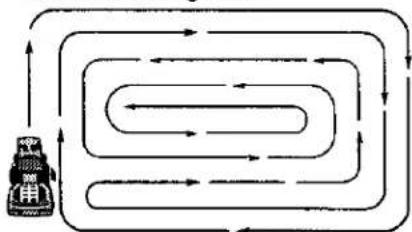
- Drive so that clippings are discharged onto the area that has been cut. Have the cut area to the right of the tractor. This will result in a more even distribution of clippings and more uniform cutting.
-
When mowing large areas, start by turning to the right so that clippings will discharge away from shrubs, fences, driveways, etc. After one or two rounds, mow in the opposite direction making left hand turns until finished.
-
If grass is extremely tall, it should be mowed twice to reduce load and possible fire hazard from dried clippings. Make first cut relatively high; the second to the desired height.
- Do not mow grass when it is wet. Wet grass will plug mower and leave undesirable clumps. Allow grass to dry before mowing.
- Always operate engine at full throttle when mowing to assure better mowing performance and proper discharge of material. Regulate ground speed by selecting a low enough gear to give the mower cutting performance as well as the quality of cut desired.
- When operating attachments, select a ground speed that will suit the terrain and give best performance of the attachment being used.
flowchart
graph TD
    A["Robot Icon"] --> B["Looped Path"]
    B --> C["Inner Loop"]
    C --> D["Outer Loop"]
    D --> E["Inner Loop"]
    E --> F["Outer Loop"]
    F --> G["Inner Loop"]
    G --> H["Outer Loop"]
    H --> I["Inner Loop"]
    I --> J["Outer Loop"]
    J --> K["Inner Loop"]
    K --> L["Outer Loop"]
    L --> M["Inner Loop"]
    M --> N["Outer Loop"]
    N --> O["Inner Loop"]
    O --> P["Outer Loop"]
    P --> Q["Inner Loop"]
    Q --> R["Outer Loop"]
    R --> S["Inner Loop"]
    S --> T["Outer Loop"]
    T --> U["Inner Loop"]
    U --> V["Outer Loop"]
    V --> W["Inner Loop"]
    W --> X["Outer Loop"]
    X --> Y["Inner Loop"]
    Y --> Z["Outer Loop"]
MAINTENANCE
| MAINTENANCE SCHEDULEFILL IN DATESAS YOU COMPLETEREGULAR SERVICE | ||||||||||||
| TRACTOR | Check Brake Operation | √ | √ | |||||||||
| Check Tire Pressure | √ | √ | ||||||||||
| Check Operator Presence andInterlock Systems | √ | |||||||||||
| Check for Loose Fasteners | √ | √2 | √ | |||||||||
| Sharpen/Replace Mower Blades | √3 | |||||||||||
| Lubrication Chart | √ | √ | ||||||||||
| Check Battery Level | √4 | |||||||||||
| Clean Battery and Terminals | √ | √ | ||||||||||
| Check Transade Cooling | √ | |||||||||||
| Adjust Blade Belt(a) Tension | √5 | |||||||||||
| Adjust Motion Drive Belt(a) Tension | √6 | |||||||||||
| ENGINE | Check Engine Oil Level | √ | √ | |||||||||
| Change Engine Oil | √12,3 | √ | ||||||||||
| Clean Air Filter | √2 | |||||||||||
| Clean Air Screen | √2 | |||||||||||
| Inspect Muffler/Spark Arrester | √ | |||||||||||
| Replace Oil Filter (if equipped) | √2 | |||||||||||
| Clean Engine Cooling Fins | √2 | |||||||||||
| Replace Spark Plug | √ | √ | ||||||||||
| Replace Air Filter Paper Cartridge | √2 | |||||||||||
| Replace Fuel Filter | √ | |||||||||||
1 - Change more often when operating under a heavy load or in high ambient temperatures.
2 - Service more often when operating in dirty or dusty conditions.
3 - if equipped with oil mill, change oil every 50 hours.
4 - Replace blades more often when mowing in sandy soil.
5.1 equipped with adjustable system.
6 - Not required II equipped with maintenance-free battery.
7. Tighten front side plate bolt to 35.8 - 100. maximum
Do not overnight.
GENERAL RECOMMENDATIONS
The warranty on this tractor does not cover items that have been subjected to operator abuse or negligence. To receive full value from the warranty, operator must maintain tractor as instructed in this manual.
Some adjustments will need to be made periodically to properly maintain your tractor.
All adjustments in the Service and Adjustments section of this manual should be checked at least once each season.
- Once a year you should replace the spark plug, clean or replace air filter, and check blades and belts for wear. A new spark plug and clean air filter assure proper air-fuel mixture and help your engine run better and last longer.
BEFORE EACH USE
- Check engine oil level.
- Check brake operation.
- Check tire pressure.
- Check operator presence and interlock systems for proper operation.
- Check for loose fasteners.
LUBRICATION CHART
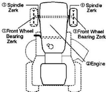
①SAE OR 10W30 MOTOR OIL ②REFER TO MAINTENANCE "ENGINE" SECTION
IMPORTANT: Do not oil or grease the pivot points which have special nylon bearings. Viscous lubricants will attract dust and dirt that will shorten the life of the self-lubricating bearings. If you feel they must be lubricated, use only a dry, powdered graphite type lubricant sparingly.
TRACTOR
Always observe safety rules when performing any maintenance.
BRAKE OPERATION
If tractor requires more than six (6) feet stopping distance at high speed in highest gear, then brake must be adjusted. (See "TO ADJUST BRAKE" in the Service and Adjustments section of this manual).
TIRES
- Maintain proper air pressure in all tires (See "PRODUCT SPECIFICATIONS" section of this manual).
- Keep tires free of gasoline, oil, or insect control chemicals which can harm rubber.
- Avoid stumps, stones, deep nuts, sharp objects and other hazards that may cause tire damage.
NOTE: To seal tire punctures and prevent flat tires due to slow leaks, tire sealant may be purchased from your local parts dealer. Tire sealant also prevents tire dry rot and corrosion.
Be sure operator presence and interlock systems are working properly. If your tractor does not function as described, repair the problem immediately.
- The engine should not start unless the clutch/brake pedal is fully depressed and attachment clutch control is in the disengaged position.
- When the engine is running, any attempt by the operator to leave the seat without first setting the parking brake should shut off the engine.
- When the engine is running and the attachment clutch is engaged, any attempt by the operator to leave the seat should shut off the engine.
- The attachment clutch should never operate unless the operator is in the seat.
BLADE CARE
For best results mower blades must be kept sharp. Replace bent or damaged blades.
BLADE REMOVAL
- Raise mower to highest position to allow access to blades.
- Remove hex bolt, lock washer and flat washer securing blade.
- Install new or resharpened blade with trailing edge up towards deck as shown.
IMPORTANT: To ensure proper assembly, center hole in blade must align with star on mandrel assembly.
-
Reassemble hex bolt, lock washer and flat washer in exact order as shown.
-
Tighten bolt securely (27-35 Ft. Lbs. torque).
IMPORTANT: Blade bolt is grade 8 heat treated.
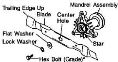
*A Grade 8 heat treated bolt can be identified by six lines on the bolt head.
TO SHARPEN BLADE
NOTE: We do not recommend sharpening blade - but if you do, be sure the blade is balanced.
Care should be taken to keep the blade balanced. An unbalanced blade will cause excessive vibration and eventual damage to mower and engine.
- The blade can be sharpened with a file or on a grinding wheel. Do not attempt to sharpen while on the mower.
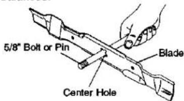
- To check blade balance, you will need a 5/8" diameter steel bolt, pin, or a cone balancer. (When using a cone balancer, follow the instructions supplied with balancer.)
NOTE: Do not use a nail for balancing blade. The lobes of the center hole may appear to be centered, but are not.
- Slide blade on to an unthreaded portion of the steel bolt or pin and hold the bolt or pin parallel with the ground. If blade is balanced, it should remain in a horizontal position. If either end of the blade moves downward, sharpen the heavy end until the blade is balanced.
BATTERY
Your tractor has a battery charging system which is sufficient for normal use. However, periodic charging of the battery with an automotive charger will extend its life.
- Keep battery and terminals clean.
- Keep battery bolts tight.
- Keep small vent holes open.
- Recharge at 6-10 amperes for 1 hour. NOTE: The original equipment battery on your tractor is maintenance free. Do not attempt to open or remove caps or covers. Adding or checking level of electrolyte is not necessary.
TO CLEAN BATTERY AND TERMINALS
Corrosion and dirt on the battery and terminals can cause the battery to "leak" power.
- Open battery box door.
- Disconnect BLACK battery cable first then RED battery cable and remove battery from tractor.
- Rinse the battery with plain water and dry.
- Clean terminals and battery cable ends with wire brush until bright.
- Coat terminals with grease or petroleum jelly.
- Reinstall battery (See "REPLACING BATTERY" in the SERVICE AND ADJUSTMENTS section of this manual).
V-BELTS
Check V-belts for deterioration and wear after 100 hours of operation and replace if necessary. The belts are not adjustable. Replace belts if they begin to slip from wear.
TRANSAXLE COOLING
Keep transaxle free from build-up of dirt and chaff which can restrict cooling.
ENGINE
LUBRICATION
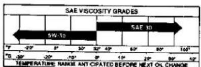
Only use high quality detergent oil rated with API service classification SF-SJ Select the oil's SAE viscosity grade according to your expected operating temperature.
bar
SAE VISCOSITY GRADES | Temperature Range (°C) | SAE 30 | SAE 5W-12 | | :--- | :--- | :--- | | -20 | | | | -10 | | | | 0 | | | | 10 | | | | 20 | | | | 30 | | | | 40 | | | | 50 | | | | 60 | | | | 70 | | | | 80 | | | | 90 | | | | 100 | | | TOMATURATE RANGE ANT CIPATED BEFORE HEXT OIL CHANGENOTE: Although multi-viscosity oils (5W30, 10W30 etc.) improve starting in cold weather, these multi-viscosity oils will result in increased oil consumption when used above 32°F. Check your engine oil level more frequently to avoid possible engine damage from running low on oil.
Change the oil after every 25 hours of operation or at least once a year if the tractor is not used for 25 hours in one year.
Check the crankcase oil level before starting the engine and after each eight (8) hours of operation. Tighten oil fill cap/dipstick securely each time you check the oil level.
TO CHANGE ENGINE OIL
Determine temperature range expected before oil change. All oil must meet API service classification SF-SJ.
- Be sure tractor is on level surface.
- Oil will drain more freely when warm.
- Catch oil in a suitable container.
- Remove oil fill cap/dipstick. Be careful not to allow dirt to enter the engine when changing oil.
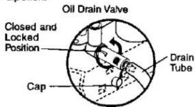
- Remove cap from end of drain valve and install the drain tube onto the fitting.
- Unlock drain valve by pushing inward slightly and turning counterclockwise.
- To open, pull out on the drain valve.
- After oil has drained completely, close and lock the drain valve by pushing inward and turning clockwise until the pin is in the locked position as shown.
- Remove the drain tube and replace the cap onto to the end of the drain valve.
- Refill engine with oil through oil fill dipstick tube. Pour slowly. Do not overfill. For approximate capacity see "PRODUCT SPECIFICATIONS" section of this manual.
- Use gauge on oil fill cap/dipstick for checking level. Be sure dipstick cap is tightened securely for accurate reading. Keep oil at "FULL" line on dipstick.
CLEAN AIR SCREEN
Air screen must be kept free of dirt and chaff to prevent engine damage from overheating. Clean with a wire brush or compressed air to remove dirt and stubborn dried gum fibers.
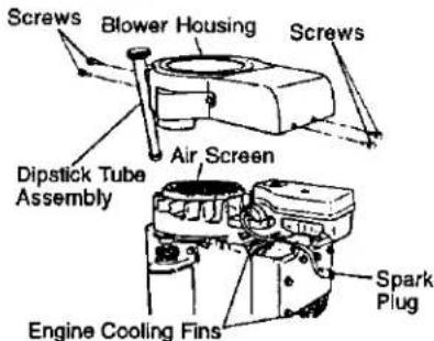
ENGINE COOLING FINS
Remove any dust, dirt or oil from engine cooling fins to prevent engine damage from overheating.
- Remove screws from blower housing and lift housing and dipstick tube assembly off engine.
- Cover oil fill opening to prevent entry of dirt.
- Use compressed air or stiff bristle brush to thoroughly clean engine cooling fins.
- To reassemble, reverse above procedure.
AIR FILTER
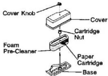
Your engine will not run properly using a dirty air filter. Clean the foam pre-cleaner after every 25 hours of operation or every season. Service paper cartridge every 100 hours of operation or every season, whichever occurs first.
Service air cleaner more often under dusty conditions.
- Remove knob(s) and cover.
TO SERVICE PRE-CLEANER
- Slide foam pre-cleaner off cartridge.
- Wash it in liquid detergent and water.
- Squeeze it dry in a clean cloth.
- Saturate it in engine oil. Wrap it in clean, absorbent cloth and squeeze to remove excess oil.
NOTE: If very dirty or damaged, replace pre-cleaner.
- Reinstall pre-cleaner over cartridge.
- Reinstall cover and secure with knob(s).
TO SERVICE CARTRIDGE
- Remove cartridge nut.
- Carefully remove cartridge to prevent debris from entering carburetor. Clean base carefully to prevent debris from entering carburetor.
- Clean cartridge by tapping gently on flat surface.
NOTE: If very dirty or damaged, replace cartridge.
4. Reinstall cartridge, nut, precleaner, cover and secure with knob(s).
IMPORTANT: Petroleum solvents, such as kerosene, are not to be used to clean the cartridge. They may cause deterioration of the cartridge. Do not oil cartridge. Do not use pressurized air to clean or dry cartridge.
MUFFLER
Inspect and replace corroded muffler and spark arrester (if equipped) as it could create a fire hazard and/or damage.
SPARK PLUGS
Replace spark plugs at the beginning of each mowing season or after every 100 hours of operation, whichever occurs first. Spark plug type and gap setting are shown in "PRODUCT SPECIFICATIONS" section of this manual.
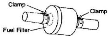
IN-LINE FUEL FILTER
The fuel filter should be replaced once each season. If fuel filter becomes clogged, obstructing fuel flow to carburetor, replacement is required.
- With engine cool, remove filter and plug fuel line sections.
- Place new fuel filter in position in fuel line with arrow pointing towards carburetor.
- Be sure there are no fuel line leaks and clamps are properly positioned.
- Immediately wipe up any spilled gasoline.
20
CLEANING
- Clean engine, battery, seat, finish, etc. of all foreign matter.
- Keep finished surfaces and wheels free of all gasoline, oil, etc.
- Protect painted surfaces with automotive type wax.
We do not recommend using a garden hose to clean your tractor unless the electrical system, muffler, air filter and carburetor are covered to keep water out. Water in engine can result in a shortened engine life.
SERVICE AND ADJUSTMENTS

CAUTION: BEFORE PERFORMING ANY SERVICE OR ADJUSTMENTS:
- Depress clutch/brake pedal fully and set parking brake.
- Place gearshift lever in neutral (N) position.
- Place attachment clutch in "DISENGAGED" position.
- Turn ignition key "OFF" and remove key.
- Make sure the blades and all moving parts have completely stopped.
- Disconnect spark plug wire from spark plug and place wire where it cannot come in contact with plug.
TRACTOR
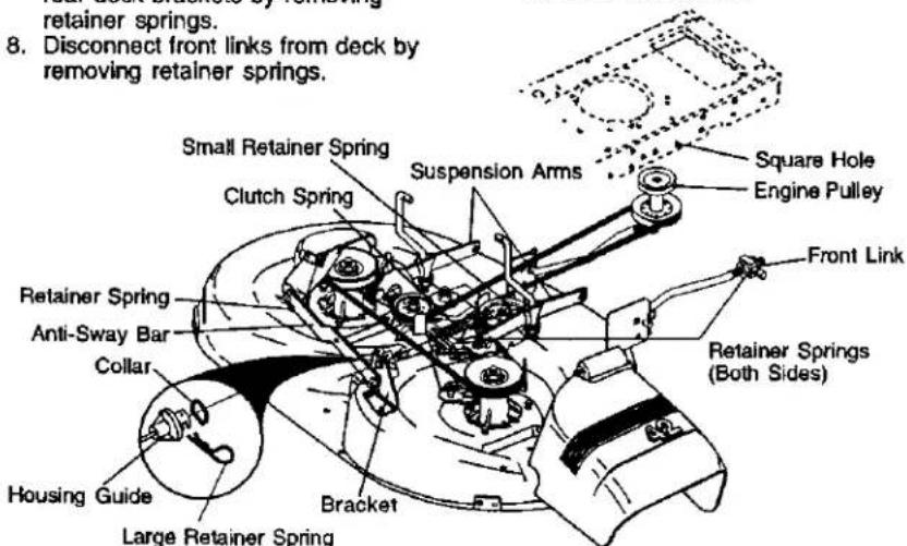
TO REMOVE MOWER
Mower will be easier to remove from the right side of tractor.
- Place attachment clutch in "DISENGAGED" position.
- Move attachment lift lever forward to lower mower to its lowest position.
- Roll belt off engine pulley.
- Remove small retainer spring, and lift clutch spring off pulley bolt.
- Remove large retainer spring, slide collar off and push housing guide out of bracket.
- Disconnect anti-swaybar from chassis bracket by removing retainer spring.
- Disconnect suspension arms from rear deck brackets by removing retainer springs.
-
Disconnect front links from deck by removing retainer springs.
-
Raise lift lever to raise suspension arms. Slide mower out from under tractor.
IMPORTANT: If an attachment other than the mower deck is to be mounted on the tractor, remove the front links and hook the clutch spring into square hole in frame.
TO INSTALL MOWER
- Raise attachment lift lever to its highest position.
- Slide mower under tractor with discharge guard to right side of tractor.
- Lower lift lever to its lowest position.
- Install mower in reverse order of removal instructions.
Adjust the mower while tractor is parked on level ground or driveway. Make sure tires are properly inflated (See "PRODUCT SPECIFICATIONS" section of this manual). If tires are over or underinflated, you will not properly adjust your mower.
SIDE-TO-SIDE ADJUSTMENT
- Raise mower to its highest position.
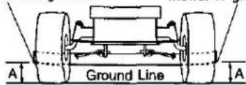
- At the midpoint of both sides of mower, measure height from bottom edge of mower to ground. Distance "A" on both sides of mower should be the same or within 1/4" of each other.
- If adjustment is necessary, make adjustment on one side of mower only.
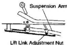
• To raise one side of mower, tighten lift link adjustment nut on that side.
• To lower one side of mower, loosen lift link adjustment nut on that side.
NOTE: Each full turn of adjustment nut will change mower height about 1/8".
- Recheck measurements after adjusting.
Bottom edge of mower to ground Bottom edge of mower to ground
FRONT-TO-BACK ADJUSTMENT
IMPORTANT: Deck must be level side-to-side. If the following front-to-back adjustment is necessary, be sure to adjust both front links equally so mower will stay level side-to-side.
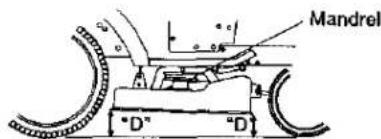
To obtain the best cutting results, the mower housing should be adjusted so that the front is approximately 1/8" to 1/2" lower than the rear when the mower is in its highest position.
Check adjustment on right side of tractor. Measure distance "D" directly in front and behind the mandrel at bottom edge of mower housing as shown.
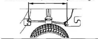
- Before making any necessary adjustments, check that both front links are equal in length.
- If links are not equal in length, adjust one link to same length as other link.
- To lower front of mower loosen nut "E" on both front links an equal number of turns.
- When distance "D" is 1/8" to 1/2" lower at front than rear, tighten nuts "F" against trunnion on both front links.
- To raise front of mower, loosen nut "F" from trunnion on both front links. Tighten nut "E" on both front links an equal number of turns.
- When distance "D" is 1/8" to 1/2" lower at front than rear, tighten nut "F" against trunnion on both front links.
- Recheck side-to-side adjustment.
Both Front Links Should be Equal in Length
natural_image
Technical line drawing of a tire mounted on a vehicle wheel, showing structural components and measurement lines (no text or symbols)
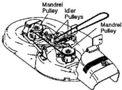
TO REPLACE MOWER BLADE DRIVE BELT
The mower blade drive belt may be replaced without tools. Park the tractor on level surface. Engage parking brake.
BELT REMOVAL -
- Remove mower from tractor (See "TO REMOVE MOWER" in this section of this manual).
- Work belt off both mandrel pulleys and idler pulleys.
- Pull belt away from mower.
BELT INSTALLATION -
- Install new belt in reverse order of removal.
- Make sure belt is in all pulley grooves and inside all belt guides.
- Install mower in reverse order of removal instructions.
TO ADJUST BRAKE
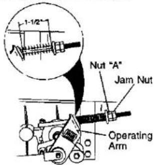
Your tractor is equipped with an adjustable brake system which is mounted on the right side of the transaxie.
If tractor requires more than six (6) feet stopping distance at high speed in highest gear on a level dry concrete or paved surface, then brake must be adjusted.
- Depress clutch/brake pedal and engage parking brake.
- Measure distance between brake operating arm and nut "A" on brake rod.
-
If distance is other than 1-1/2", loosen jam nut and turn nut "A" until distance becomes 1-1/2". Retighten jam nut against nut "A".
-
Road test tractor for proper stopping distance as stated above. Readjust if necessary. If stopping distance is still greater than six (6) feet in highest gear, further maintenance is necessary. Contact a Sears or other qualified service center.
With Parking Brake "Engaged"
TO REPLACE MOTION DRIVE BELT
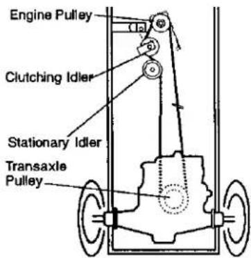
Park the tractor on level surface. Engage parking brake. For assistance, there is a belt installation guide decal on bottom side of left footrest.
- Remove mower (See "TO REMOVE MOWER" in this section of this manual.)
- Remove belt from stationary idler and clutching idler.
- Pull belt slack toward rear of tractor. Remove belt upwards from transaxle pulley by deflecting belt keepers.
- Pull belt toward front of tractor and remove downwards from around engine pulley.
- Install new belt by reversing above procedure.
TO ADJUST STEERING WHEEL ALIGNMENT
If steering wheel crossbars are not horizontal (left to right) when wheels are positioned straight forward, remove steering wheel and reassemble per instructions in the Assembly section of this manual.
FRONT WHEEL TOE-IN/CAMBER
The front wheel toe-in and camber are not adjustable on your tractor. If damage has occurred to affect the front wheel toe-in or camber, contact a Sears or other qualified service center.
TO REMOVE WHEEL FOR REPAIRS
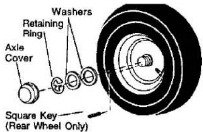
- Block up axle securely.
- Remove axle cover, retaining ring and washers to allow wheel removal (rear wheel contains a square key - Do not lose).
- Repair tire and reassemble. NOTE: On rear wheels only: align grooves in rear wheel hub and axle. Insert square key.
- Replace washers and snap retaining ring securely in axle groove.
- Replace axle cover. NOTE: To seal tire punctures and prevent flat tires due to slow leaks, tire sealant may be purchased from your local parts dealer. Tire sealant also prevents tire dry rot and corrosion.
TO START ENGINE WITH A WEAK BATTERY
CAUTION: Lead-acid batteries generate explosive gases. Keep sparks, flame and smoking materials away from batteries. Always wear eye protection when around batteries.
If your battery is too weak to start the engine, it should be recharged. (See "BATTERY" in the MAINTENANCE section of this manual). If "jumper cables" are used for emergency starting, follow this procedure:
IMPORTANT: Your tractor is equipped with a 12 volt negative grounded system. The other vehical must also be a 12 volt negative grounded system. Do not use your tractor battery to start other vehicles.
TO ATTACH JUMPER CABLES -
- Connect each end of the RED cable to the POSITIVE (+) terminal of each battery, taking care not to short against chassis.
- Connect one end of the BLACK cable to the NEGATIVE (-) terminal of fully charged battery.
- Connect the other end of the BLACK cable to good CHASSIS GROUND, away from fuel tank and battery.
TO REMOVE CABLES, REVERSE ORDER-
- BLACK cable first from chassis and then from the fully charged battery.
- RED cable last from both batteries.
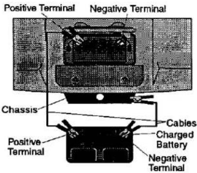
REPLACING BATTERY
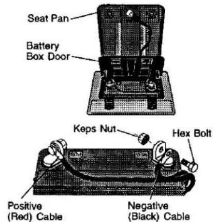
A CAUTION: Do not short battery terminals by allowing a wrench or any other object to contact both terminals at the same time. Before connecting battery, remove metal bracelets, wristwatch bands, rings, etc. Positive terminal must be connected first to prevent sparking from accidental grounding.
- Lift seat pan to raised position and open battery box door.
- Disconnect BLACK battery cable first then RED battery cable and carefully remove battery from tractor.
- Install new battery with terminals in same position as old battery.
- First connect RED battery cable to positive (+) terminal with hex bolt and keps nut as shown. Tighten securely.
- Connect BLACK grounding cable to negative (-) terminal with remaining hex bolt and keps nut. Tighten securely.
- Close battery box door.
TO REPLACE HEADLIGHT BULB
- Raise hood.
- Pull bulb holder out of the hole in the backside of the grill.
- Replace bulb in holder and push bulb holder securely back into the hole in the backside of the grill.
- Close hood.
INTERLOCKS AND RELAYS
Loose or damaged wiring may cause your tractor to run poorly, stop running, or prevent it from starting.
- Check wiring. See electrical wiring diagram in the Repair Parts section. TO REPLACE FUSE
Replace with 20 amp automotive-type plug-in fuse. The fuse holder is located behind the dash.
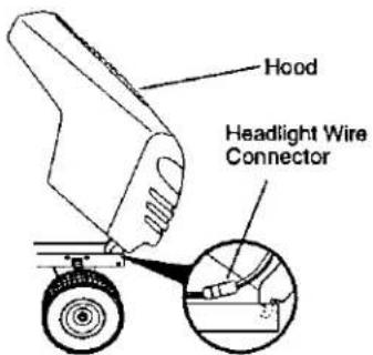
TO REMOVE HOOD AND GRILL ASSEMBLY
- Raise hood.
- Unsnap headlight wire connector.
- Stand in front of tractor. Grasp hood at sides, tilt toward engine and lift off of tractor.
- To replace, reverse above procedure.
ENGINE
Maintenance, repair, or replacement of the emission control devices and systems, which are being done at the customers expense, may be performed by any non-road engine repair establishment or individual. Warranty repairs must be performed by an authorized engine manufacturer's service outlet.
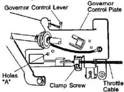
TO ADJUST THROTTLE CONTROL CABLE
The throttle control has been preset at the factory and adjustment should not be necessary. Check adjustment as described below before loosening cable. If adjustment is necessary, proceed as follows:
-
With engine not running, move throttle control lever from slow to choke position. Slowly move lever from choke to fast position.
-
Check that holes "A" in governor control lever and hole in governor plate line-up. If holes "A" are not aligned, loosen clamp screw and move throttle cable until holes are aligned. Tighten clamp screw securely.
TO ADJUST CARBURETOR
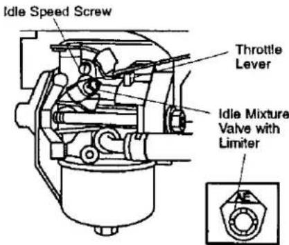
NOTE: The carburetor on this engine is low emission. It is equipped with an idle fuel adjusting needle with a limiter cap, which allows some adjustment within the limits allowed by the cap. Do not attempt to remove the limiter cap. The limiter cap cannot be removed without breaking the adjusting needle.
The carburetor has been preset at the factory and adjustment should not be necessary. However, minor adjustment may be required to compensate for differences in fuel, temperature, altitude or load. If the carburetor does need adjustment, proceed as follows: In general, turning idle mixture valve in (clockwise) decreases the supply of fuel to the engine giving a leaner fuel/air mixture. Turning the idle mixture valve out (counter-clockwise) increases the supply of fuel to the engine giving a richer fuel/air mixture. IMPORTANT: Damage to the needle valve and the seat in carburetor may result if screw is turned in too tight.
PRELIMINARY SETTING -
- Air cleaner assembly must be assembled to the carburetor when making carburetor adjustments.
- Be sure the throttle control cable is adjusted properly (see above).
FINAL SETTING -
- Start engine and allow to warm for five minutes. Make final adjustments with engine running and shift/motion control lever in neutral (N) position.
- Move throttle control lever to slow position. With finger, rotate and hold throttle lever against idle speed screw. Turn idle speed screw to attain 1750 RPM.
- While still holding throttle lever against idle speed screw, turn idle mixture valve full travel clockwise then counterclockwise until engine runs rough. Turn valve to a point midway between those two positions. Release throttle lever.
ACCELERATION TEST
- Move throttle control lever from slow to fast position. If engine hesitates or dies, turn idle mixture valve out (counterclockwise) 1/8 turn. Repeat test and continue to adjust, if necessary, until engine accelerates smoothly.
High speed stop is factory adjusted. Do not adjust - damage may result.
IMPORTANT: Never tamper with the engine governor, which is factory set for proper engine speed. Overspeeding the engine above the factory high speed setting can be dangerous. If you think the engine-governed high speed needs adjusting, contact a Sears or other qualified service center, which has proper equipment and experience to make any necessary adjustments.
STORAGE
Immediately prepare your tractor for storage at the end of the season or if the tractor will not be used for 30 days or more.
A CAUTION: Never store the tractor with gasoline in the tank inside a building where fumes may reach an open flame or spark. Allow the engine to cool before storing in any enclosure.
TRACTOR
Remove mower from tractor for winter storage. When mower is to be stored for a period of time, clean it thoroughly, remove all dirt, grease, leaves, etc. Store in a clean, dry area.
- Clean entire tractor (See "CLEANING" in the Maintenance section of this manual).
- Inspect and replace belts, if necessary (See belt replacement instructions in the Service and Adjustments section of this manual).
- Lubricate as shown in the Maintenance section of this manual.
- Be sure that all nuts, bolts and screws are securely fastened. Inspect moving parts for damage, breakage and wear. Replace if necessary.
- Touch up all rusted or chipped paint surfaces; sand lightly before painting.
BATTERY
• Fully charge the battery for storage.
• After a period of time in storage, battery may require recharging.
- To help prevent corrosion and power leakage during long periods of storage, battery cables should be disconnected and battery cleaned thoroughly (see "TO CLEAN BATTERY AND TERMINALS" in the Maintenance section of this manual).
• After cleaning, leave cables disconnected and place cables where they cannot come in contact with battery terminals.
- If battery is removed from tractor for storage, do not store battery directly on concrete or damp surfaces.
ENGINE
FUEL SYSTEM
IMPORTANT: It is important to prevent gum deposits from forming in essential fuel system parts such as carburetor, fuel hose, or tank during storage. Also,
experience indicates that alcohol blended fuels (called gasohol or using ethanol or methanol) can attract moisture which leads to separation and formation of acids during storage. Acidic gas can damage the fuel system of and engine while in storage.
- Drain the fuel tank.
- Start the engine and let it run until the fuel lines and carburetor are empty.
- Never use engine or carburetor cleaner products in the fuel tank or permanent damage may occur.
• Use fresh fuel next season.
NOTE: Fuel stabilizer is an acceptable alternative in minimizing the formation of fuel gum deposits during storage. Add stabilizer to gasoline in fuel tank or storage container. Always follow the mix ratio found on stabilizer container. Run engine at least 10 minutes after adding stabilizer to allow the stabilizer to reach the carburetor. Do not drain the gas tank and carburetor if using fuel stabilizer.
ENGINE OIL
Drain oil (with engine warm) and replace with clean engine oil. (See "ENGINE" in the Maintenance section of this manual).
CYLINDER(S)
- Remove spark plug(s).
- Pour one ounce of oil through spark plug hole(s) into cylinder(s).
- Tum ignition key to "START" position for a few seconds to distribute oil.
- Replace with new spark plug(s).
OTHER
- Do not store gasoline from one season to another.
- Replace your gasoline can if your can starts to rust. Rust and/or dirt in your gasoline will cause problems.
- if possible, store your tractor indoors and cover it to give protection from dust and dirt.
- Cover your tractor with a suitable protective cover that does not retain moisture. Do not use plastic. Plastic cannot breathe which allows condensation to form and will cause your tractor to rust.
IMPORTANT: Never cover tractor while engine and exhaust areas are still warm.
TROUBLESHOOTING CHART
| PROBLEM | CAUSE | CORRECTION |
| Will not start | 1. Out of fuel.2. Engine not “CHOKED” properly.3. Engine flooded.4. Bad spark plug.5. Dirty air filter.6. Dirty fuel filter.7. Water in fuel.8. Loose or damaged wiring.9. Carburetor out of adjustment.10. Engine valves out of adjustment. | 1. Fill fuel tank.2. See “TO START ENGINE” in Operation section.3. Wait several minutes before attempting to start.4. Replace spark plug.5. Clean/replace air filter.6. Replace fuel filter.7. Drain fuel tank and carburetor, refill tank with fresh gasoline and replace fuel filter.8. Check all wiring.9. See “To Adjust Carburetor” in Service Adjustments section.10. Contact a Sears or other qualified service center. |
| Hard to start | 1. Dirty air filter.2. Bad spark plug.3. Weak or dead battery.4. Dirty fuel filter.5. Stale or dirty fuel.6. Loose or damaged wiring.7. Carburetor out of adjustment.8. Engine valves out of adjustment. | 1. Clean/replace air filter.2. Replace spark plug.3. Recharge or replace battery.4. Replace fuel filter.5. Drain fuel tank and refill with fresh gasoline.6. Check all wiring.7. See “To Adjust Carburetor” in Service Adjustments section.8. Contact a Sears or other qualified service center. |
| Engine will not turn over | 1. Brake pedal not depressed.2. Attachment clutch is engaged.3. Weak or dead battery.4. Blown fuse.5. Corroded battery terminals.6. Loose or damaged wiring.7. Faulty ignition switch.8. Faulty solenoid or starter.9. Faulty operator presence switch(es). | 1. Depress brake pedal.2. Disengage attachment clutch.3. Recharge or replace battery.4. Replace fuse.5. Clean battery terminals.6. Check all wiring.7. Check/replace ignition switch.8. Check/replace solenoid or starter.9. Contact a Sears or other qualified service center. |
| Engine clicks but will not start | 1. Weak or dead battery.2. Corroded battery terminals.3. Loose or damaged wiring.4. Faulty solenoid or starter. | 1. Recharge or replace battery.2. Clean battery terminals.3. Check all wiring.4. Check/replace solenoid or starter. |
TROUBLESHOOTING CHART
| PROBLEM | CAUSE | CORRECTION |
| Loss of power | 1. Cutting too much grass/too fast.2. Throttle in “CHOKE” position.3. Build-up of grass, leaves and trash under mower.4. Dirty air filter.5. Low oil level/dirty oil.6. Faulty spark plug.7. Dirty fuel filter.8. Stale or dirty fuel.9. Water in fuel.10. Spark plug wire loose.11. Dirty engine air screen/fins.12. Dirty/clogged muffler.13. Loose or damaged wiring.14. Carburetor out of adjustment.15. Engine valves out of adjustment. | 1. Set in “Higher Cut” position/reduce speed.2. Adjust throttle control.3. Clean underside of mower housing.4. Clean/replace air filter.5. Check oil level/change oil.6. Clean and regap or change spark plug.7. Replace fuel filter.8. Drain fuel tank and refill with fresh gasoline.9. Drain fuel tank and carbure-tor, refill tank with fresh gasoline and replace fuel filter.10. Connect and tighten spark plug wire.11. Clean engine air screen/fins.12. Clean/replace muffler.13. Check all wiring.14. See “To Adjust Carburetor” in Service Adjustments section.15. Contact a Sears or other qualified service center. |
| Excessive vibration | 1. Worn, bent or loose blade.2. Bent blade mandrel.3. Loose/damaged part(s). | 1. Replace blade.Tighten blade bolt.2. Replace blade mandrel.3. Tighten loose part(s).Replace damaged parts. |
| Engine continues to run when operator leaves seat with with attachment clutch engaged | 1. Faulty operator-safety presence control system. | 1. Check wiring, switches and connections. If not contact a Sears or other qualified service center. |
| Poor cut - uneven | 1. Worn, bent or loose blade.2. Mower deck not level.3. Buildup of grass, leaves, and trash under mower.4. Bent blade mandrel.5. Clogged mower deck vent holes from buildup of grass, leaves, and trash around mandrels. | 1. Replace blade. Tighten blade bolt.2. Level mower deck.3. Clean underside of mower housing.4. Replace blade mandrel.5. Clean around mandrels to open vent holes. |
TROUBLESHOOTING CHART
| PROBLEM | CAUSE | CORRECTION |
| Mower blades will not rotate | 1. Obstruction in clutch mechanism.2. Worn/damaged mower drive belt.3. Frozen idler pulley.4. Frozen blade mandrel. | 1. Remove obstruction.2. Replace mower drive belt.3. Replace idler pulley.4. Replace blade mandrel. |
| Poor grass discharge | 1. Engine speed too slow.2. Travel speed too fast.3. Wet grass.4. Mower deck not level.5. Low/uneven tire air pressure.6. Worn, bent or loose blade.7. Buildup of grass, leaves and trash under mower.8. Mower drive belt worn.9. Blades improperly installed.10. Improper blades used.11. Clogged mower deck vent holes from buildup of grass, leaves, and trash around mandrels. | 1. Place throttle control in “FAST” position.2. Shift to slower speed.3. Allow grass to dry before mowing.4. Level mower deck.5. Check tires for proper air pressure.6. Replace/sharpen blade. Tighten blade bolt.7. Clean underside of mower housing.8. Replace mower drive belt.9. Reinstall blades sharp edge down.10. Replace with blades listed in this manual.11. Clean around mandrels to open vent holes. |
| Headlight(s) not working (if so equipped) | 1. Switch is “OFF”.2. Bulb(s) or lamp(s) burned out.3. Faulty light switch.4. Loose or damaged wiring.5. Blown fuse. | 1. Turn switch “ON”.2. Replace bulb(s) or lamp(s).3. Check/replace light switch.4. Check wiring and connec-tions.5. Replace fuse. |
| Battery will not charge | 1. Bad battery cell(s).2. Poor cable connections.3. Faulty regulator (if so equipped).4. Faulty alternator. | 1. Replace battery.2. Check/clean all connec-tions.3. Replace regulator.4. Replace alternator. |
| Engine “backfires” when turning engine “OFF” | 1. Engine throttle control not set at “SLOW” position for 30 seconds before stopping engine. | 1. Move throttle control to “SLOW” position and allow to idle for 30 seconds before stopping engine. |
SCHEMATIC
TRACTOR - MODEL NUMBER 917.271531
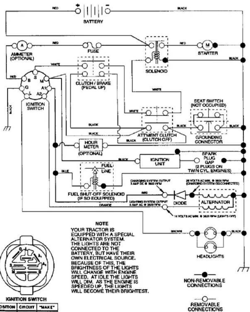
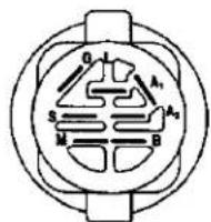
IGNITION SWITCH
| POSITION | CIRCUIT | "MAXE" |
| OFF | M+G+A1 | NONE |
| RUNLIGHT | B+A1 | A2+L |
| RUN | B+A1 | NONE |
| START | B+S+A1 | NONE |
WIRING INSULATED CLIPS
NOTE: IF WIRING INSULATED CLIPS WERE REMOVED FOR
SERVICING OF UNIT, THEY SHOULD BE REPLACED TO
PROPERLY SECURE YOUR WIRING.
REPAIR PARTS
TRACTOR - MODEL NUMBER 917.271531
ELECTRICAL
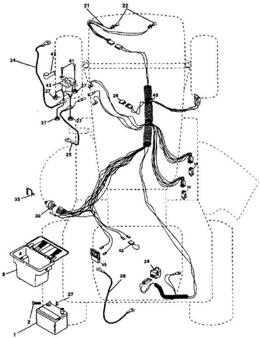
ELECTRICAL
TRACTOR -- MODEL NUMBER 917.271531
KEY PART NO. NO. DESCRIPTION
| 1 | 144925 | Battery 12 Volt 25 AMP |
| 2 | 74760412 | Bolt Hex Hd 1/4-20unc X 3/4 |
| 8 | 156417 | Case Battery |
| 16 | 153664 | Switch Interlock Push-In |
| 21 | 160181 | Harness Socket Light W/4152J |
| 22 | 4152J | Bulb Light #1156 |
| 24 | 4799J | Cable Battery 6ga 11" red |
| 25 | 146147 | Cable Battery 6 Ga W/16 Wir red |
| 26 | 175158 | Fuse 20 AMP |
| 27 | 73510400 | Nut Kaps Hex 1/4-20 Unc |
| 28 | 4207J | Cable Ground 6ga 12" black |
| 29 | 121305X | Switch Plunger Nc Gray |
| 30 | 175566 | Switch Ign Delta Push-in |
| 33 | 140403 | Key Ign Molded Craftsman, Delta |
| 40 | 178437 | Harness Ign |
| 41 | 71110408 | Bolt Bk Hex 1/4-20unc x 1/2 |
| 42 | 131563 | Cover Terminal Red |
| 43 | 178861 | Solenoid |
| 45 | 121433X | Ammeter Rectangular 6 AMP |
| 52 | 141940 | Protection Wire Loop |
NOTE: All component dimensions given In U. S. inches 1 inch = 25.4 mm
TRACTOR – MODEL NUMBER 917.271531 CHASSIS AND ENCLOSURES
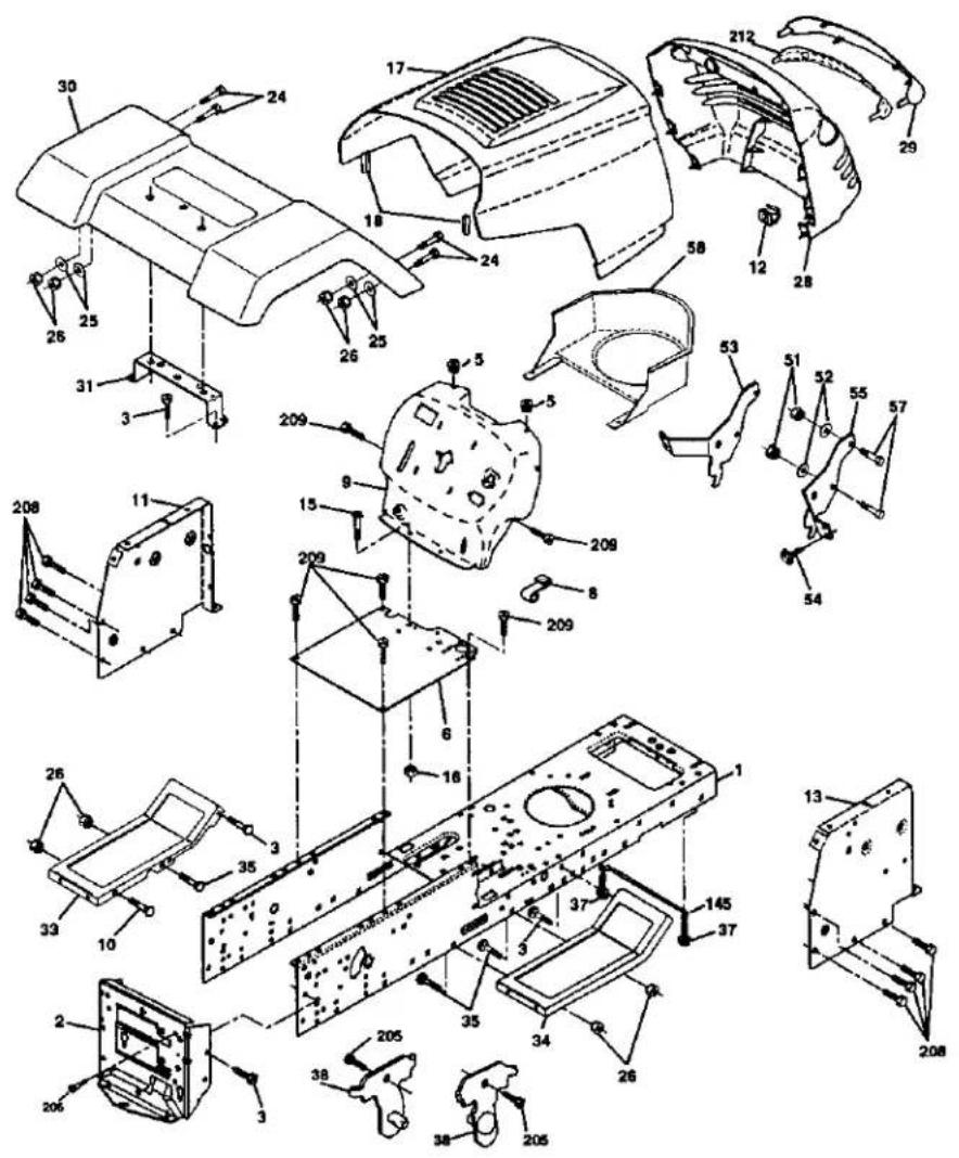
TRACTOR -- MODEL NUMBER 917.271531 CHASSIS AND ENCLOSURES
KEY PART
| NO. | NO. | DESCRIPTION |
| 1 | 174620 | Chassis Lt Stamping |
| 2 | 176554 | Drawbar |
| 3 | 17060612 | Screw 3/8-16 x 3/4 |
| 5 | 155272 | Bumper Hood/Dash |
| 6 | 174643X010 | Saddle SLKSCRE FLT SDL |
| 8 | 126471X | Clip Insulator .406 Mtg Hole |
| 9 | 168348X010 | Dash Slkscr Plm Mech Sym |
| 10 | 72140608 | Bolt RdHd Sqnk. 3/8-16 x 1 |
| 11 | 155927 | Panel Asm. Dash Lh |
| 12 | 145660 | Clip Tinnerman Grille P/L |
| 13 | 172107X010 | Panel Dash Rh |
| 15 | 74190512 | Screw Mach Trhd 5/16-18unc x 3/4 |
| 16 | 73510500 | Nu Keps 5/16-18unc |
| 17 | 159639X558 | Hood Pnt Steel Private Label |
| 18 | 126938X | Bumper Hood |
| 24 | 74780616 | Bolt Fin Hex 3/8-16 Unc x 1 Gr. 5 |
| 25 | 19131312 | Washer 13/32 x 13/16 x 12 Ga. |
| 26 | 73800600 | Nut Lock Hex w/Ins 3/8-16 Unc |
| 28 | 140434 | Grill/Lens Asm |
| 29 | 140273X599 | Lens Grille Private label |
| 30 | 169465X558 | Fender Pnt |
| 31 | 136619 | Bracket Fender Support |
| 33 | 145244X558 | Footrest Pnt. Lh |
| 34 | 145243X558 | Footrest Pnt. Rh |
| 35 | 72110606 | Bolt RdHd Sht. Sqnk. 3/8-16 x 3/4 |
| 37 | 17490508 | Screw Thdrol 5/16-18 x 1/2 Tyt |
| 38 | 175710 | Bracket Asm. Pivot Mower Rear |
| 51 | 73800400 | Nut Lock Hex W/Ins. 1/4-20 |
| 52 | 19091416 | Washer 9/32 x 7/8 x 16 Ga. |
| 53 | 144697 | Bracket Grille LH |
| 54 | 161464 | Screw Hex Wshd #8-18 x 7/8 |
| 55 | 144696 | Bracket, Grille RH |
| 57 | 74780412 | Bolt Fin Hex 1/4-20 x 3/4 |
| 58 | 150127 | Air Duct Private Label LT Engine |
| 145 | 156524 | Rod Pivot Chassis /Hood |
| 205 | 17490608 | Screw Thdrol 3/8-16 x 1/2 |
| 206 | 170165 | Bolt Shoulder 5/16-18 TT |
| 208 | 17670608 | Screw Thdrol. 3/8-16 x 1/2 |
| 209 | 17000612 | Screw Hex Wsh Thdrol 3/8-16 BL |
| 212 | 156229 | Insert Lens Reflective |
| -- | 5479J | Plug Button Blk .359 Dia. Choke |
NOTE: All component dimensions given in U.S. inches 1 inch = 25.4 mm
GROUND DRIVE
TRACTOR - MODEL NUMBER 917.271531
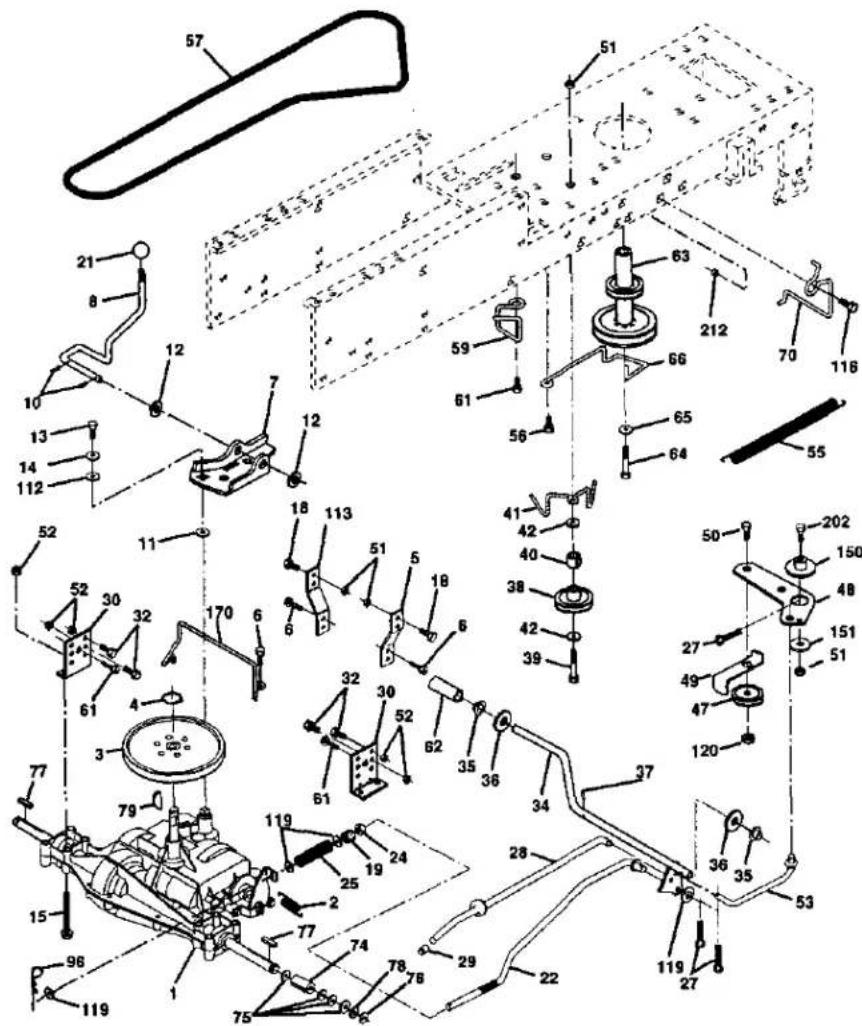
TRACTOR - MODEL NUMBER 917.271531
GROUND DRIVE
KEY PART
NO. NO.
| 1 | ---- | Transaxle (See Breakdown)Dana 4360-140 |
| 2 | 146682 | Spring Return Brake T/a Zinc |
| 3 | 123666X | Pulley Transaxle 18/20" tires |
| 4 | 12000028 | Ring Retainer # 5100-62 |
| 5 | 121520X | Strap Torque 30 Degrees |
| 6 | 17060512 | Screw 5/16-18 x 3/4 |
| 7 | 162240 | Bracket Saddle Shift T/a |
| 8 | 131679 | Rod Shf Sci LY/YT Str Blk Zinc |
| 10 | STD561210 | Pin Cotter 1/8 x 1 Cad |
| 11 | 105701X | Washer Plate Shf 398 Sq Hole |
| 12 | 19151216 | Washer 15/32 x 3/4 x 16ga |
| 13 | 74550412 | Bolt 1/4-28unf Gr8 W/Patch |
| 14 | STD551125 | Washer Lock Hvy Hellcal 1/4 |
| 15 | 74490544 | Bolt Hex FLGHD 5/16-18 Gr.5 |
| 18 | STD523710 | Bolt Fin Hex 3/8-16 x 1 |
| 19 | STD541437 | Nut Lock Hex W/Ins. 3/8-16 Unc |
| 21 | 106933X | Knob Rd 1/2-13 Piste Thds Blk |
| 22 | 130804 | Rod Brake Blk Zinc 26 840 |
| 24 | STD541237 | Nut Hex Jam 3/8-16 Unc |
| 25 | 106888X | Spring Rod Brako 2 00 Zinc |
| 26 | 19131016 | Washer 13/32 x 5/8 x 16 Ga |
| 27 | STD561210 | Pin Cotter 1/8 x 3/4 Cad |
| 28 | 175765 | Rod Brake Parking Lt/Yt |
| 29 | 71673 | Cap Brake Parking |
| 30 | 174973 | Bracket Mtg Transaxle |
| 32 | STD523107 | Bolt Hox Hd 5/16-18unc x 3/4 |
| 34 | 175578 | Shaft Asm Pedal Foot |
| 35 | 120183X | Bearing Nylon Blk 629 Id |
| 36 | STD551062 | Washer 21/32 x 1 x 16 Ga |
| 37 | STD571810 | Pin Roll 3/16 x 1" |
| 38 | 165936 | Pulley Idler Flat |
| 39 | 74760648 | Bolt Fin Hex 3/8-16 Unc X 3 |
| 40 | 175461 | Spacer Split |
| 41 | 175556 | Keeper Bolt Idler |
| 42 | 19131312 | Washer 13/32 x 13/16 x 12 Ga |
KEY PART
| NO. | NO. | DESCRIPTION |
| 47 | 127783 | Pulley Idler V Groove Plastic |
| 48 | 154407 | Bellcrank Clutch Gm Drv Sll |
| 49 | 123205X | Retainer Belt Style Spring |
| 50 | STD523715 | Bolt Hex Hd 3/8-16 unc x 1-1/2 |
| 51 | STD541437 | Nut Crownlock 3/8-16 UNC |
| 52 | STD541431 | Nut Crown Lock 5/16-18 |
| 53 | 105710X | Link Clutch 7 66 |
| 55 | 105709X | Spring Return Clutch 6 75 |
| 56 | STD523712 | Bolt Fin Hex 3/8-16 unc x 1-1/4 |
| 57 | 180855 | V-Belt Gd Drive |
| 59 | 169691 | Keeper Bolt Centerspan |
| 61 | 17060612 | Screw 3/8-16 x 3/4 |
| 62 | 8883R | Cover Pedal Blk Round |
| 63 | 175410 | Pulley Eng |
| 64 | 71170764 | Bolt Hex 7/16-20 x 4 Gr 5 |
| 65 | STD551143 | Washer Lock Hvy Hicl Spr 7/16 |
| 66 | 154778 | Keeper Bolt Engine |
| 70 | 134683 | Guide Bolt Mower Drive RH |
| 74 | 109502X | Spacer Axle |
| 75 | 121749X | Washer 25/32 x 1 1/4 x 16 Ga |
| 76 | STD581075 | E-ring #5133-75 |
| 77 | 123583X | Key Square 2 0 x 1845/ 1865 |
| 78 | 121748X | Washer 25/32 x 1-5/8 x 16 Ga |
| 79 | 2228M | Key |
| 96 | 4497H | Retainer Spring 1.00 |
| 112 | 19061210 | Washer 9/32 x 3/4 x 10 Ga |
| 113 | 127285X | Strap Torque |
| 116 | 72110608 | Bolt Rdhd Sq Neck 3/8-16 x 1 |
| 120 | 73900600 | Nut Lock Flg 3/8-16 |
| 150 | 174456 | Spacer Retainer |
| 151 | 19133210 | Washer 13/32 x 2 x 10 Ga |
| 170 | 173898 | Keeper Bolt Transaxle Gear |
| 202 | 72110614 | Bolt Carr Sh 3/8-16 x 1-3/4 Gr. 5 |
| 212 | 145212 | Nut Hex Flange Lock |
| NOTE: All component dimensions given in U. S. inches 1 inch = 25.4 mm | ||
STEERING
TRACTOR -- MODEL NUMBER 917.271531
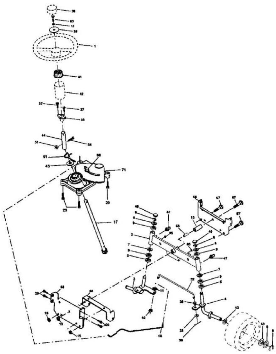
STEERING
TRACTOR - MODEL NUMBER 917.271531
KEY PART
| NO. | NO. | DESCRIPTION |
| 1 | 139768 | Wheel Steering Opp Sears Blk |
| 2 | 154427 | Axle Asm Front Lt |
| 3 | 169840 | Spindle Asm Lh |
| 4 | 169839 | Spindle Asm Rh |
| 5 | 6266H | Washer Thrust .75 x 1.230 |
| 6 | 121748X | Washer 25/32 x 1-5/8 x 16 Ga. |
| 7 | 19272016 | Washer 27/32 x 1-1/4 x 16 Ga. |
| 8 | 12000029 | RingKlip #T5304-75 |
| 9 | 3366R | Bearing Col Strg Blk |
| 10 | 175121 | Draglink |
| 11 | 10040600 | Washer Lock Hvy Hicl Spr 3/8 |
| 13 | 136518 | Spacer Brg Axle Front |
| 15 | 145212 | Nut Hexllange Lock |
| 17 | 177876 | Shaft Asm Strg |
| 26 | 126847X | Bushing Link Drag Blk LR |
| 27 | 136874 | Gear Sector 22 Teeth |
| 28 | 19131416 | Washer 13/32 x 7/8 x 16 Ga. |
| 29 | 17060612 | Screw 3/8-16 x 3/4 |
| 32 | 130465 | Rod Tie Wire Form 19.75 Mach |
| 36 | 155099 | Bushing Strg. 5/8 ID Dash |
| 37 | 152927 | Screw |
| 38 | 139769 | Cap Wheel Steer Opp Soars USA |
| 39 | 19133812 | Washer 13/32 x 2-3/8 x 12 Ga. |
| 40 | 7810H | Nut Lock Center 3/8-24 |
| 41 | 100711L | Adaptor Wheel Strg. |
| 42 | 145054X428 | Boot Steering Dash P/L MTL Blk |
| 43 | 121749X | Washer 25/32 x 1-1/4 x 16 Ga. |
| 44 | 153720 | Extension Steering Non-adjust |
| 46 | 121232X | Cap Spindle Fr Top Blk |
| 47 | 6855M | Fitting Grease |
| 51 | 73800500 | Nut Lock Hx W/Ins 5/16-18unc |
| 54 | 74780520 | Bolt Fin Hex 5/16-18unc |
| 63 | 74780616 | Bolt Fin Hex 3/8-16unc x 1 Gr. 5 |
| 65 | 160367 | Spacer Axle |
| 67 | 72140618 | Bolt Rohd 3/8-16 x 2-1/4 |
| 68 | 169827 | Brace Axle |
| 71 | 175146 | Steering Asm |
| 82 | 169635 | Bracket Susp Chasis Front |
| 85 | 133835 | Fastner Christmas Tree |
| 88 | 175118 | Bolt Shoulder 7/16-20 Unc |
| 91 | 175553 | Clip Steering |
NOTE: All component dimensions given in U. S. inches 1 inch = 25.4 mm
ENGINE
TRACTOR - MODEL NUMBER 917.271531
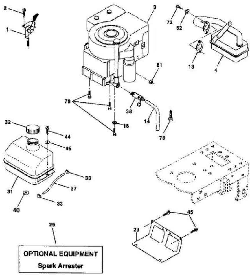
ENGINE
TRACTOR - MODEL NUMBER 917.271531
KEY PART
NO. NO.
DESCRIPTION
1 170545
2 17720410
3 ....
(五) 会议审议情况
4 137352
13 165291
14 148456
16 STD551237
23 169837
29 137160
31 109202X
32 158990
33 123487X
37 137040
38 148315
40 124028X
44 17670412 Screw Hexwsh Thdrol 1/4-20 x 3/4
45 17000612
46 19091416
62 STD551131
72 71070512
78 17060620
81 73510400
Control Th/eh
Screw Hex Thd Cut 1/4-20x5/8 T
Engine (See Breakdown)
Briggs, Model No 287707-1255-E3
Muffler Exh LT B&S 14HP IC OHV
Gasket Eng 1 313 Id Tin Plated
Tube, drain
Washer Lock Ext Tooth 3/8
Shield Browning/Debris Guard
Kit Spark Arrestor (Flat Scm)
Tank Fuel Front 1 25
Cap Asm Fuel Sears Vented
Clamp Hose Blk
Line Fuel 20"
Plug, drain
Bushing Snap Nyl Blk Fuel Line
Screw Hexwsh Thdrol 1/4-20 x 3/4
Screw Hex wsh Thdr 3/8-16 x /4
Washer 9/32 x 7/8 x 16 ga
Washer Lock Hvy Hicl Spr 5/16
Screw Hex Hd Cap 5/16-18 X 3/4
Screw 3/8-16 x 1-1/4
Nut Keps Hex 1/4-20 Unc
NOTE: All component dimensions given in U. S.
inches 1 inch = 25.4 mm
TRACTOR -- MODEL NUMBER 917.271531
SEAT ASSEMBLY
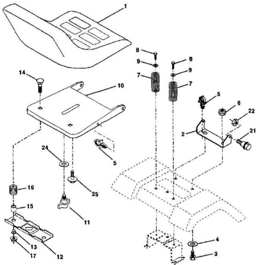
KEY PART
NO. NO.
1 140122
2 140551
3 71110618
4 19131610
5 145006
6 STD541437
7 124181X
8 17000616
9 19131614
10 174894
11 166369
12 121246X
DESCRIPTION
Seat
Bracket Pvt St
Bolt Fin Hex 3/8-16unc X 1
Washer Flat 13/32 X 1 X 10 Ga
Clip Push-In Hinged
Locknut Hex W/Wsh 3/8-16
Spring Seat Cprsn 2 250 Bk Zi
Scrow 3/8-16 X 1-1/2
Washer 13/32 X 1 X 14 Ga
Pan Seat
Knob Seat Adl. Winoput
Bracket Mounting Switch
KEY PART
NO. NO.
13 121248X
14 72050412
15 134300
16 121250X
17 123976)
21 171852
22 STD541431
24 19171912
25 127018X
DESCRIPTION
Bushing Snap Blk Nvl 50 Id
Bolt Rdhd Shl Nk 1/4-20x1-1/2
Spacer Split 28x 96 Yel Zinc
Spring Cprsn 1 27 Btk Pnl
Nut Lock 1/4 Lge Flg Gr 5 Zinc
Bolt Shld 5/16-18 Unc-2A Blk D
Nut Lock Hex "W/Ins 5/16-18
Washer 17/32 X 1-3/16 X 12 Ga
Bolt Shoulder 5/16-18 x .62
NOTE: All component dimensions given in U.S.
inches 1 inch = 25.4 mm
DECALS
TRACTOR – MODEL NUMBER 917.271531
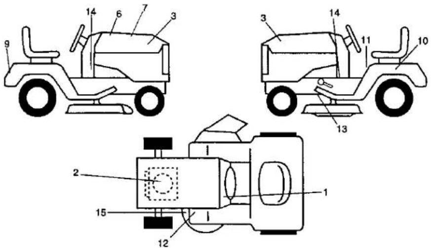
KEY PART
| NO. | NO. | DESCRIPTION |
| 1 | 156867 | Decal Dash Inst Oper English |
| 2 | 176675 | Decal HP Engine |
| 3 | 171704 | Decal Hood Logo |
| 6 | 133644 | Decal Maint Cust SearsDomestic |
| 7 | 174210 | Decal Replcmnt Sears |
| 9 | 163204 | Decal Fendor Craftsman White |
| 10 | 149516 | Decal Battery Dngr/Psn EngAcme |
| 11 | 156439 | Decal Danger Fender Eng/span |
KEY PART
| NO. | NO. | DESCRIPTION |
| 12 | 4900J | Decal Clutch/brake English |
| 13 | 146046 | Decal V-Bolt Dr Sch Tractor |
| 14 | 177097 | Decal Panel Dash 6sp 42" |
| 15 | 160396 | Decal V-Bolt Sch |
| -- | 157199X428 | Pad Footrest |
| -- | 138311 | Decal Handle Lift Height Adjust |
| -- | 178124 | Manual Owners English |
| -- | 178125 | Manual Owners Spanish |
WHEELS AND TIRES
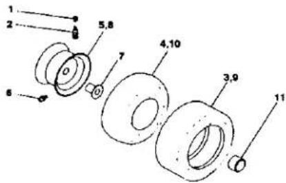
KEY PART
| NO. | NO. | DESCRIPTION |
| 1 | 59192 | Cap Value Tire |
| 2 | 65139 | Stem Value |
| 3 | 106222X | Tire F Ts 15 X 6 0 - 6 Service |
| 4 | 59904 | Tube Inner Front #35060 |
| 5 | 106732X427 | Rim Asm 6"front White Service |
| 6 | 278H | Fitting Grease |
| 7 | 9040H | Bearing Flange |
| 8 | 106108X427 | Rim Asm 8"rear White Service |
| 9 | 124635X | Tire R Ts 18x9 5-8 Service |
| 10 | 7152J | Tube Rear 9 5 X 8 Service |
| 11 | 104757X428 | Cap Axle Blk 1 50 X 1 00 |
| -- | 144334 | Sealant, Tire (10 oz. tube) |
NOTE: All component dimensions given in U. S.
inches 1 inch = 25.4 mm
LIFT ASSEMBLY
TRACTOR -- MODEL NUMBER 917.271531
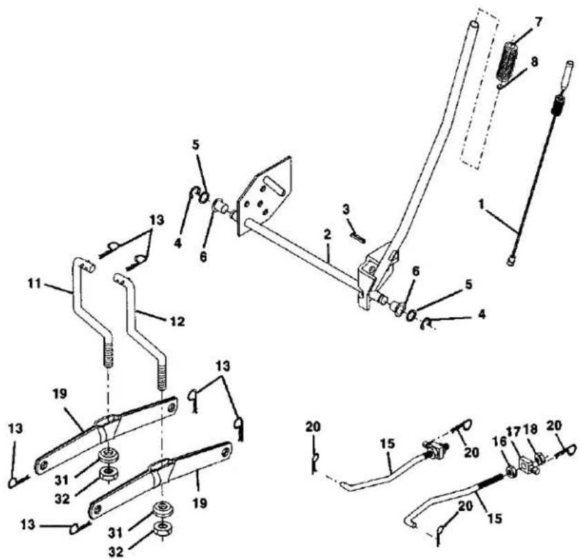
TRACTOR - MODEL NUMBER 917.271531 LIFT ASSEMBLY
KEY PART
NO. NO.
DESCRIPTION
1 159460 Wire Asm Inner/Sprg W/plunger LT
2 159471 Shaft Asm Lift
3 105767X Pin Groove 1 500 Zinc
4 12000002 ERing#5133-62
5 19211621 Washer Pfd 21/32 X 1 X 21ga
6 120183X Bearing Nylon Blk 629 Id
7 125631X Grip Handle Fluted Blk
8 122365X Button Plunger Red
11 139865 Link Lift LH
12 139866 Link Lift RH
13 STD624008 Retainer Spring
15 173288 Link Front
16 73350800 Nut Jam Hex 1/2-13 Unc
17 175689 Trunnion
18 73800800 Nut Lock W/Wsh 1/2-13unc
19 139868 Arm Suspension Rear
20 163552 Retainer Spring Zinc
31 169865 Bearing Pvt Lift
32 73540600 Nut Crownlock 3/8-24
NOTE: All component dimensions given in U. S.
inches 1 inch = 25.4 mm
TRACTOR -- MODEL NUMBER 917.271531
MOWER DECK
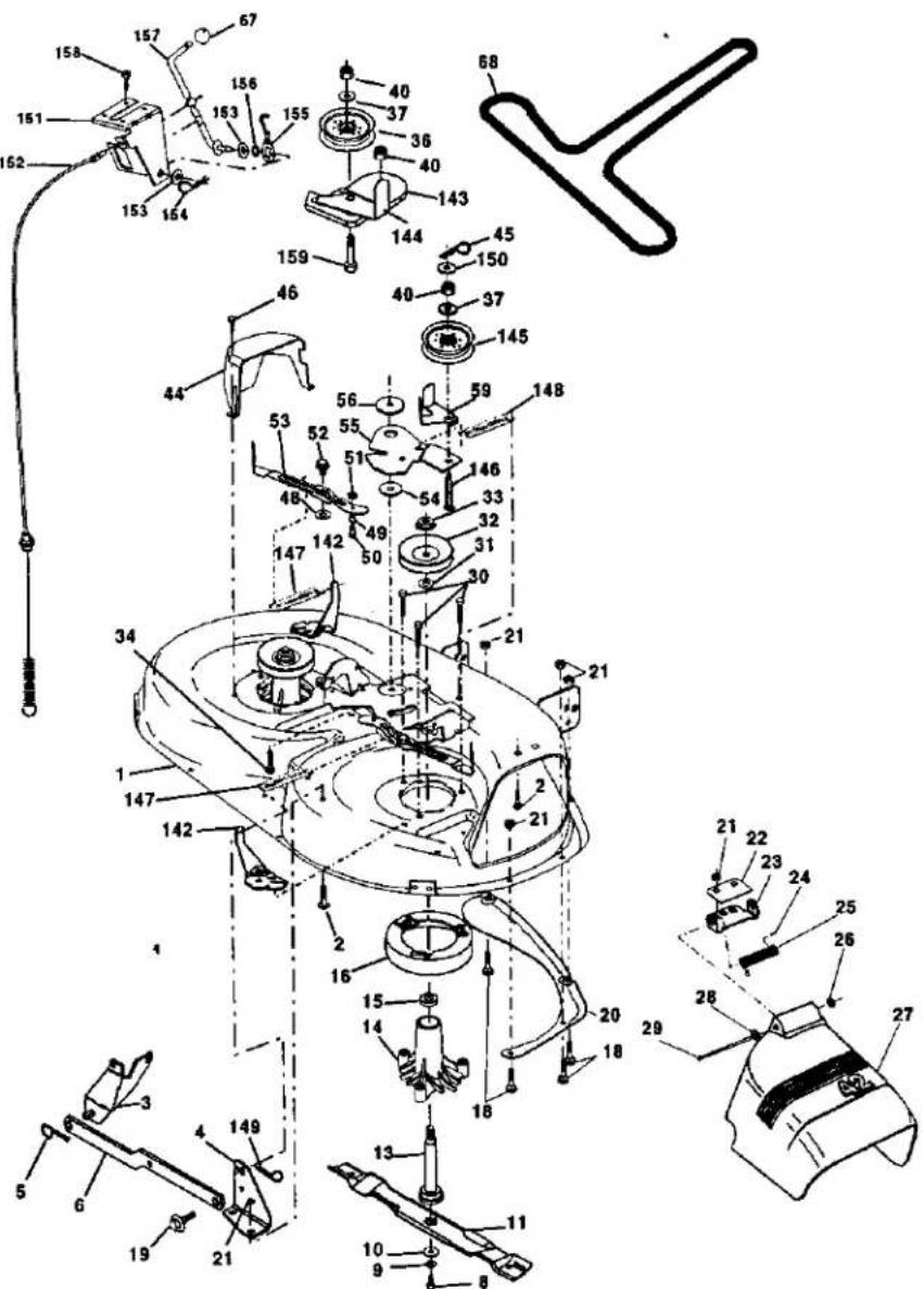
TRACTOR - MODEL NUMBER 917.271531
MOWER DECK
| KEYNO. | PARTNO. | DESCRIPTION | KEYNO. | PARTNO. | DESCRIPTION |
| 1 | 165892 | Mower Deck Assembly, 42" | 48 | 133944 | Washer, Hardened |
| 2 | STD533107 | Bolt | 49 | 174284 | Roller Assembly, Cam |
| 3 | 138017 | Bracket Assembly, Sway Bar, Front | 50 | 131340 | Follower |
| 4 | 165460 | Bracket Sway Bar 38/42" Deck | 51 | STD541410 | Bolt, Shoulder #10-24 Grade 5 |
| 5 | STD624008 | Retainer Spring | 52 | 139888 | Locknut |
| 6 | 130832 | Arm, Suspension, Rear | 53 | 131845 | Bolt, Shoulder 5/16-18 UNC |
| 8 | 850857 | Bolt, Hex 3/8-24 x 1.25 Gr. 8 | 54 | 133943 | Arm Assembly, Pad, Brake |
| 9 | STD551137 | Washer, Lock | 55 | 155048 | Washer, HardenedArm, Idler |
| 10 | 140296 | Washer, Hardened | 56 | 165723 | Spacer, Rotainer |
| 11 | 134149 | Blade, Mulching | 59 | 141043 | Guard, TUV Idler |
| 13 | 137645 | Shaft Assembly, Mandrel | 67 | 149848 | Knob Custom Oval |
| 14 | 128774 | Housing, Mandrel, Vented | 68 | 144959 | V-Belt |
| 15 | 110485X | Bearing, Ball, Mandrel | 142 | 165890 | Arm Spring Brake Mower |
| 16 | 174493 | Stripper, Vented Mower Deck | 143 | 157109 | Bracket Arm Idler 42" |
| 18 | 72140505 | Bolt, Carriage 5/16-18 x 5/8 | 144 | 158634 | Keeper Belt 42" Clutch Cable |
| 19 | 132827 | Bolt, Shoulder | 145 | 165888 | Pulley Idler Flat |
| 20 | 159770 | Baffle, Vortex | 148 | 171977 | Bolt Carriage Idler |
| 21 | STD541431 | Nut Crownlock 5/16-18 UNC | 147 | 131335 | Spring Extension |
| 22 | 134753 | Stiffener Bracket | 148 | 169022 | Spring Return Idler |
| 23 | 131267 | Bracket, Deflector | 149 | 165898 | Retainer Spring Yellow Zinc |
| 24 | 105304X | Cap, Sleeve | 150 | 19091216 | Washer 9/32 x 3/4 x 16 Ga. |
| 25 | 123713X | Spring, Torsion, Deflector | 151 | 169670 | Bracket Clutch |
| 26 | 110452X | Nut, Push | 152 | 169676 | Cable Clutch 42 In |
| 27 | 130968X428 | Shield, Deflector | 153 | 169674 | Washer Flat 3/8" Type B |
| 28 | 19111016 | Washer 11/32 x 5/8 x 16 Ga. | 154 | 169675 | Spring Retainer |
| 29 | 131491 | Rod, Hinge | 155 | 169671 | Spring Retention Lever |
| 30 | 157722 | Screw Thdrol Washer Head | 156 | 169672 | Spacer |
| 31 | 129963 | Washer, Spacer | 157 | 169669 | Rod Clutch |
| 32 | 153535 | Pulley, Mandrel | 158 | 17720410 | Screw Hex Thd Cut 1/4-20 x 5/8 |
| 33 | 178342 | Nut, Toplock, Flanged | 159 | 72140614 | Bolt Rdhd Sqn 3/8-16unc x 1-3/4 |
| 34 | STD533717 | Bolt Rdhd 3/8-16 x 1-3/4 | -- | 130794 | Mandrel Assembly (Includes |
| 36 | 131494 | Pulley, Idler, Fiat | Key Numbers 6-10, 13-15, 31 and 32) | ||
| 37 | STD551037 | Washer 13/32 x 13/16 x 16 Gauge | -- | 169583 | Replacement Mower, Complete |
| 40 | STD541437 | Nut Crownlock 3/8-16 UNC | |||
| 44 | 140088 | Guard, Mandrel, L.H. | NOTE: All component dimensions given in U. S.inches 1 inch = 25.4 mm | ||
| 45 | STD624003 | Retainer | |||
| 46 | 137729 | Screw, Thd. Roll 1/4-20 x 5/8 | |||
TRACTOR-MODEL NUMBER 917.271531
DANA TRANSAXLE-MODEL NUMBER D4360-140
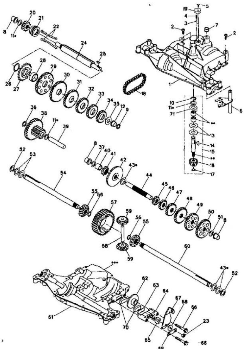
TRACTOR - MODEL NUMBER 917.271531 DANA TRANSAXLE-MODEL NUMBER D4360-140
| KEYNO. | PARTNO. | DESCRIPTION | KEYNO. | PARTNO. | DESCRIPTION |
| 1 | 170981 | Housing, Upper | 40 | 120472X | Spacer, .633 X .87 X .755 |
| 2 | 2274J | Screw, Tapping, 1/4-20 X .734 | 41 | 105928X | Sprocket, 9T |
| 42 | 170988 | Gear, Bevel, 36T | |||
| 3 | 134400 | Ball, Detent | 43 | 134394 * | Assy, Kit, Shim, .750 Shaft |
| 4 | 105904X | Spring, Detent | 44 | 120473X | Shaft, Drive |
| 5 | 160940 | Screw, Tapping, No. 10-24 X .482 | 45 | 142678 | Gear, Spur, 12T |
| 46 | 143697 | Gear, Spur, 15T | |||
| 6 | 138235 | Assy, Kit, Shifter | 47 | 124641X | Gear, Spur, 20T |
| 7 | 108727X | V-Ring | 48 | 106589X | Gear, Spur, 25T |
| 8 | 148266 | Bearing, Flange | 49 | 120408X | Gear, Spur, 28T |
| 9 | 148269 | Seal, Oil | 50 | 105937X | Gear, Spur, 31T |
| 10 | 2225J | Ring, Retaining | 51 | 2226J | Washer, Plain, .632 X 1.00 X .060 |
| 11 | 134793 * | Assy, Kit, Shim, .625 Shaft | |||
| 12 | 148268 | Bearing, Flange | 52 | 134401 | Washer, Neoprene |
| 13 | 120415X | Washer, Plain, .632 X 1.38 X .046 | 53 | 2264J | Washer, Plain, .758 X 1.25 X .031 |
| 14 | 142674 | Key, Woodruff, No. 9 | 54 | 160946 | Axle, LH |
| 15 | 170983 | Assy, Kit, Input Shaft | 55 | 170990 | Gear, Miter, 1 2T, Splined |
| 16 | 170986 | Pinion, Bevel, 12T | 56 | 160948 | Ring, Retaining |
| 17 | 105909X | Ring, Retaining | 57 | 110071X | Gear, Spur, 32T |
| 18 | 105910X | Chain, 24 Pitches | 58 | 120952X | Shaft, Cross |
| 19 | 160942 | Cover, Detent | 59 | 170991 | Gear, Miter, 1 2T, Idler |
| 20 | 150943 | Gear, Spur, 1 2T | 60 | 160950 | Axle, RH |
| 21 | 148267 | Collar, Clutch | 61 | 170992 | Housing, Lower |
| 22 | 138236 | Assy, Kit, Clutch Keys | 62 | 7294J | Disc, Brake |
| 23 | 73810500 | Nut, Lock, 5/16-24 | 63 | 108989X | Spacer, Brake Puck |
| 24 | 142676 | Shaft, Intermediate | 64 | 160952 | Jaw, Brake |
| 25 | 2244J | Key, Woodruff, No. 61 | 65 | 120954X | Pin, Dowel |
| 26 | 105916X | Ring, Retaining | 66 | 160953 | Screw, Tapping, 5/16-18 X 2.35 |
| 27 | 120470X | Sprocket, 1 8T | |||
| 28 | 110070X | Spacer, 1. 131 X 1.45 X .494 | 67 | 138244 | Lever, Actuating |
| 68 | 108996X | Washer, Plain, .321 X 1.00 X .055 | |||
| 29 | 142677 | Gear, Spur, 37T | |||
| 30 | 142681 | Gear, Spur, 35T | 69 | 160954 | Bracket, Anti-Rotation |
| 31 | 124644X | Gear, Spur, 30T | 70 | 120951X | Puck, Friction |
| 32 | 108980X | Gear, Spur, 25T | 71 | 174256 | Washer, Anti Rotation |
| 33 | 120406X | Gear, Spur, 22T | 72 | 120416X | Grease |
| 34 | 134796 | Gear, Spur, 19T | |||
| 35 | 105925X | Washer, Plain, .640 X 1.37 X .061 | NOTE: All component dimensions given in U.S. inches 1 inch = 25.4 mm | ||
| 36 | 2228J | Washer, Plain, .632 X 1.00 X .046 | • Use in various combinations to maintain properclearances. | ||
| 37 | 170987 | Washer, Plain, .632 X 1.00 X .031 | •• Order Key No. 15. | ||
| 38 | 174255 | Assy, Gear, Comb., 12T & 30T | ••• Silicone Sealant to be applied between Upperand LowerHousings (use Loctite Ultra Gray Silicone 5699 or equivalent). | ||
| 39 | 124639X | Shaft, Idler | |||
TRACTOR - MODEL NUMBER 917.271531
BRIGGS & STRATTON ENGINE-MODEL NUMBER 287707, TYPE NUMBER 1255-E3
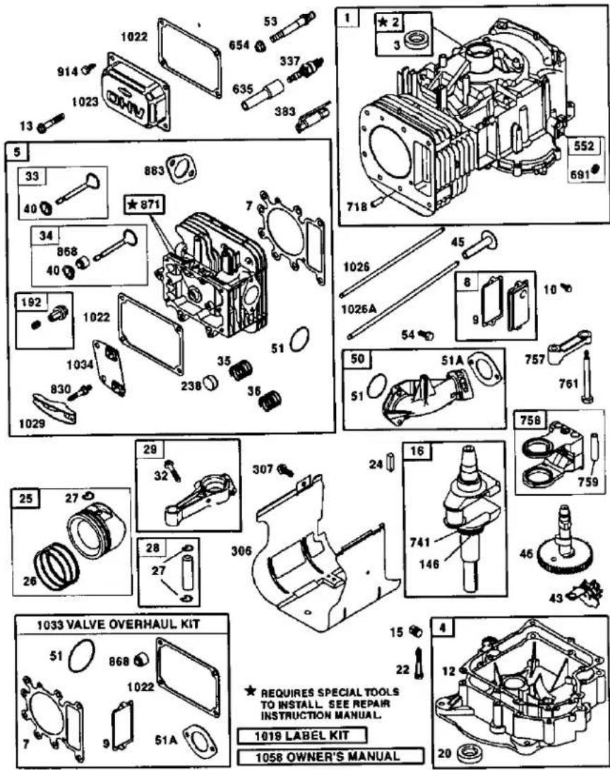
TRACTOR -- MODEL NUMBER 917.271531
BRIGGS & STRATTON ENGINE-MODEL NUMBER 287707, TYPE NUMBER 1255-E3
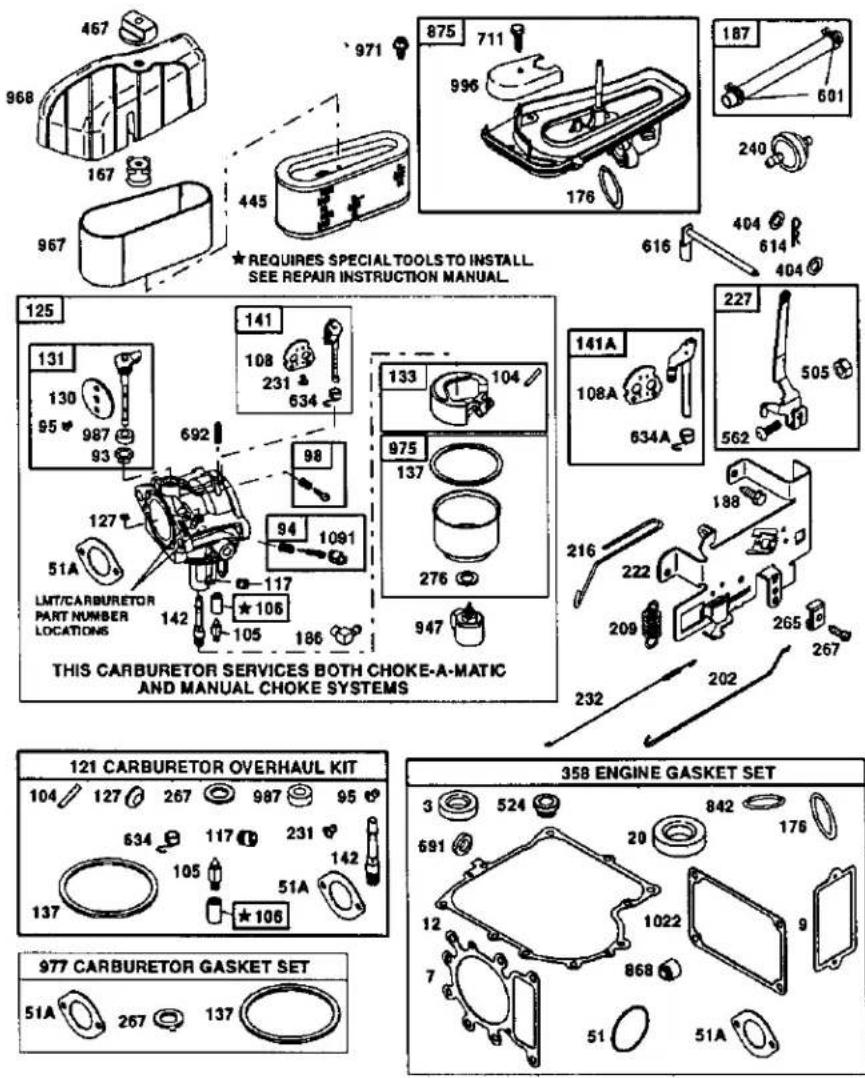
TRACTOR – MODEL NUMBER 917.271531
BRIGGS & STRATTON ENGINE-MODEL NUMBER 287707, TYPE NUMBER 1255-E3
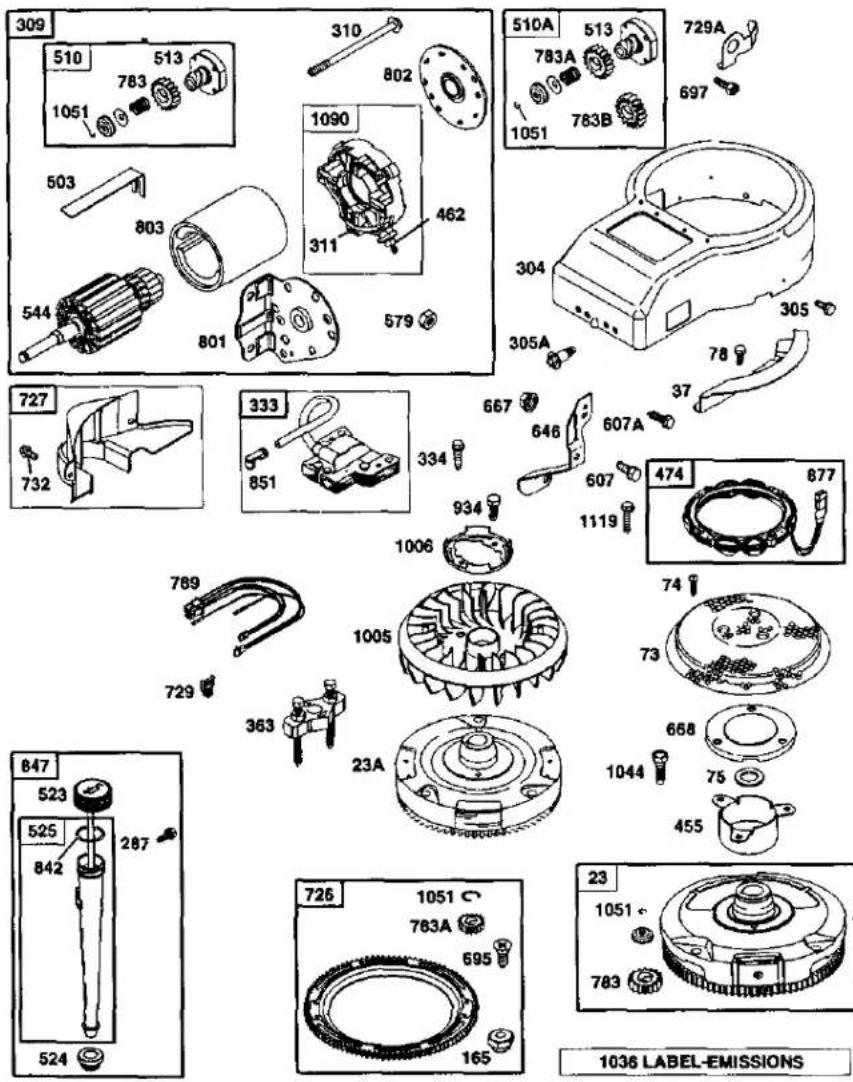
TRACTOR - MODEL NUMBER 917.271531
BRIGGS & STRATTON ENGINE-MODEL NUMBER 287707, TYPE NUMBER 1255-E3
| KEYNO. | PARTNO. | DESCRIPTION | KEYNO. | PARTNO. | DESCRIPTION |
| 1 | 496412 | Cylinder Assembly | 98 | 495800 | Kit-Idle Speed |
| 2 | 399265 | Bushing/Seal Kit | 104 | 231789 | ∅ Pin-Float Hinge |
| 3 | 391086 | • Seal-Oil | 105 | 231855 | ∅ Valve-Float Needle |
| 4 | 494238 | Sump-Engine | 106 | 231854 | ∅ Seat-Inlet |
| 5 | 691165 | Head-Cylinder | 108 | 224558 | Valve-Choke (Manual Choke) |
| 7 | 273280 | •+ Gasket-Cylinder Head | |||
| 8 | 495735 | Breather Assembly | 108A | 224540 | Valve-Choke (Choke-A-Matic) |
| 9 | 27803 | • Gasket-Breather | |||
| 10 | 94621 | Screw (Breather Assembly) | 117 | 232118 | ∅ Jet, Main (Standard) |
| 11 | 281246 | Tube-Breather | 232119 | Jet, Main (High Altitude) | |
| 12 | 271916 | • Gasket-Crankcase (.015" Thick, Std.) | 121 | 690191 | Carburetor Overhaul Kit |
| 125 | 690194 | Carburetor | |||
| 271997 | • Gasket-Crankcase (.005" Thick) | 127 | — — — | ∅ Plug-Welch (Sold in Kit Only) | |
| 130 | 224539 | Valve-Throttle | |||
| 271996 | • Gasket-Crankcase (.009" Thick) | 131 | 494379 | Throttle Shaft Kit | |
| 133 | 494381 | Float-Carburetor | |||
| 13 | 94728 | Screw (Cylinder Head, 3-9/16") | 137 | 281165 | ∅‡ Gasket-Float Bowl |
| 141 | 495097 | Choke Shaft Kit (Man. Choke) | |||
| 15 | 94239 | Plug-Oil Drain | |||
| 16 | 690136 | Crankshaft | 141A | 495931 | Choke Shaft Kit (Choke-A-Matic) |
| 20 | 291675 | • Seal-Oil | |||
| 22 | 95187 | Screw (Crankcase Cover) | 142 | 232117 | ∅ Nozzle-Carburetor |
| 23 | 693557 | Flywheel (Steel Ring Gear) | 146 | 94196 | Key-Timing |
| 23A | 492326 | Flywheel (Plastic Ring Gear) | 165 | 693148 | Nut (Ring Gear) |
| 24 | 222698 | Key-Flywheel | 171 | 281051 | Nut (Air Cleaner) |
| 25 | 499284 | Piston Assembly (Std.) | 176 | 281106 | • Gasket, Air Cleaner |
| 499288 | Piston Assembly (.010 "O.S.) | 177 | 270920 | • Seal-O-Ring Connector-Hose | |
| 186 | 493496 | Line-Fuel (Cut to Required Length) | |||
| 49929 | Piston Assembly (.020" O.S.) | 187 | 492790 | ||
| 499296 | Piston Assembly (.030" O.S.) | 188 | 94929 | Screw (Control Bracket) | |
| 192 | 492160 | Adjuster, Rocker Arm | |||
| 26 | 495854 | Ring Set, Piston (Std.) | 209 | 260695 | Spring, Governor |
| 495852 | Ring Set, Piston (.010 "O.S.) | 216 | 262766 | Link-Choke | |
| 495851 | Ring Set, Piston (.020 "O.S.) | 216A | 262767 | Link-Choke | |
| 495855 | Ring Set, Piston (.030 "O.S.) | 222 | 495611 | Bracket, Control | |
| 27 | 263129 | Lock-Piston Pin | 227 | 493935 | Lever-Governor |
| 28 | 498319 | Pin Assembly, Piston (Std.) | 231 | 94098 | ∅ Screw (Choke) |
| 498320 | Pin Assembly-Piston (.005" O.S.) | 232 | 282785 | Spring-Link Cap, Valve | |
| 238 | 262836 | ||||
| 29 | 692419 | Rod-Connecting (Std.) | 240 | 394358 | Filter-Fuel |
| 499940 | Rod-Connecting (.020 U.S.) | 265 | 221535 | Clamp-Casing | |
| 32 | 692852 | Screw (Connecting Rod) | 267 | 94906 | Screw (Casing Clamp) |
| 33 | 495856 | Valve-Exhaust | 276 | 281164 | Sealing Washer |
| 34 | 495857 | Valve, Intake | 287 | 94903 | Screw (Dipstick Tube) |
| 35 | 262811 | Spring, Valve | 294 | 810104 | Adjuster-Rocker Arm |
| 37 | 224502 | Guard-Flywheel | 304 | 496281 | Housing-Blower (Black Inner) |
| 40 | 224641 | Retainer, Valve | |||
| 43 | 490815 | Governor-Oil Slinger | 305 | 94863 | Screw (Inner Blower Housing) |
| 45 | 262411 | Tappet, Valve | |||
| 46 | 496884 | Camshaf | 306 | 225020 | Shield, Cylinder |
| 48 | 496050 | ShortBlock | 307 | 94930 | Screw (Cylinder Shield) |
| 50 | 690193 | Manifold, Intake | |||
| 51 | 693138 | •+ Gasket-Intake | RPM | Settings: | Low Speed: 1900-2100 High Speed: 3000-3200 |
| 51A | 273650 | Gasket-Intake | |||
| 53 | 690227 | Stud (Carburetor) | |||
| 54 | 95160 | Screw (Intake Manifold) | • | Included in Gasket Set, Ref Number 358. | |
| 73 | 224948 | Screen, Rotating | ∅ | Included in Carburetor Kit, Ref Number 121. | |
| 74 | 94626 | Screw (Rotating Screen) | |||
| 75 | 225136 | Washer (Flywheel) | ‡ | Included in Carburetor Gasket Set, Ref Number 977. | |
| 78 | 94896 | Screw (Flywheel Guard) | |||
| 87 | 491323 | • Seal-Governor Shaft | + | Included in Value Overhaul Kit, Ref Number 1033. | |
| 93 | 281346 | Bushing-Throttle Shaft | |||
| 94 | 498030 | Valve-Idle Adjustment | |||
| 95 | 94098 | ∅ Screw (Throttle Valve) | NOTE: All component dimensions given in U.S. inches 1 inch = 25.4 mm | ||
TRACTOR - MODEL NUMBER 917.271531
BRIGGS & STRATTON ENGINE-MODEL NUMBER 287707, TYPE NUMBER 1255-E3
| KEYNO. | PARTNO. | DESCRIPTION | KEYNO. | PARTNO. | DESCRIPTION |
| 309 | 693551 | Motor-Starter(For Steel Ring Gear Only) | 729 | 281390 | Clip, Wire |
| 497595 | Motor-Starter (For Plastic Ring Gear Only) | 729A | 225170 | Clip, Wire | |
| 732 | 94625 | Screw(Starter Drive Cover) | |||
| 741 | 262932 | Gear-Timing | |||
| 310 | 94003 | Screw (Starter Motor) | 757 | 213998 | Link-Counterweight |
| 311 | 497608 | Brush Set | 758 | 499994 | Counterweight |
| 318 | 94734 | Screw (Mounting Bracket) | 759 | 230787 | Pin-Counterweight |
| 333 | 495859 | Armature, Magneto | 761 | 94593 | Screw (Counterweight) |
| 334 | 94731 | Screw (Armature | 783 | 693713 | Gear-Pinion (For Steel Ring Gear Only) |
| 337 | 491055 | Spark Plug | |||
| 358 | 690189 | Gasket Set | 783A | 693059 | Gear-Pinion (For Aluminum Ring Gear Only) |
| 353 | 19203 | Flywheel Puller | |||
| 383 | 89838 | Wrench-Spark Plug | 783B | 693058 | Gear-Pinion (For Plastic Ring Gear Only) |
| 404 | 94927 | Washer (Governor Crank) | |||
| 423 | 95163 | Screw (Air Cleaner Base) | 789 | 497708 | Harness, Wiring |
| 455 | 222561 | Cup-Flywheel | 801 | 497626 | Cap-Drive |
| 462 | 225137 | Washer (Starter Cable) | 802 | 497607 | Cap-End |
| 467 | 493903 | Knob-Air Cleaner | 803 | 497604 | Housing-Starter |
| 474 | 393474 | Alternator | 830 | 94555 | Stud-Rocker Arm |
| 503 | 806000 | Strap-Starter | 847 | 496415 | Dipstick/Tube Assembly |
| 505 | 231978 | Nut (Governor Lever) | 851 | 224110 | Terminal-Cable |
| 510A | 693699 | Drive, Starter (Use With Steel Ring Gear Only) | 868 | 499236 | Seal- Valve |
| 871 | 262835 | Bushing-Guide | |||
| 510A | 497606 | Drive, Starter (Use With Aluminum &Plastic Ring Gear Only) | 875 | 693686 | Base, Air Cleaner |
| 877 | 393456 | Wire-Alternator | |||
| 878 | 393362 | Harness-Alternator | |||
| 513 | 398003 | Clutch-Drive | 883 | 272293 | Gasket, Exhaust |
| 523 | 495230 | Dipstick | 914 | 94863 | Screw (Rocker Cover) |
| 524 | 281370 | Dipstick Tube Seal | 934 | 94627 | Screw (Fan Retainer) |
| 525 | 496113 | Dipstick Tube | 947 | 497672 | Solenoid-Fuel |
| 535 | 496894 | Filter, A/C Element | 967 | 272403 | Filter-Pre Cleaner |
| 544 | 497603 | Armature-Starter | 968 | 281758 | Cover, Air Cleaner |
| 552 | 491986 | Bushing-Gov. Lever | 975 | 495933 | Bowl-Float |
| 556 | 93621 | Screw (Alternator) | 977 | 690192 | Gasket Set-Carburetor |
| 562 | 94907 | Bolt (Governor Lever) | 987 | 281166 | Seal-Throttle Shaft |
| 579 | 92278 | Nut (Starter Cable) | 996 | 690678 | Shield-Carburetor |
| 601 | 93053 | Clamp-Hose | 1005 | 691927 | Fan-Flywheel |
| 614 | 93306 | Pin-Cotter | 1006 | 224413 | Retainer-Fan |
| 616 | 495157 | Crank-Governor | 1019 | 496758 | Label Kit |
| 634 | 494453 | Seal-Spring Assembly(Manual Choke) | 1022 | 272475 | Gasket-Rocker Cover |
| 1023 | 224552 | Cover-Rocker | |||
| 634A | 494455 | Seal-Spring Assy. (Choke-A-Matic) | 1026 | 494432 | Rod-Push (Intake) |
| 1026A | 495136 | Rod-Push (Exhaust) | |||
| 635 | 280872 | Boot, Spark Plug | 1029 | 224554 | Arm-Rocker |
| 646 | 224546 | Brace-Air Cleaner | 1033 | 690190 | Valve Overhaul Kit |
| 654 | 94010 | Nut (Carburetor) | 1034 | 495248 | Guide-Push Rod |
| 663 | 94929 | Screw (Air Cleaner Brace) | 1036 | 499364 | Label Kit-Emission |
| 663A | 94704 | Screw (Air Cleaner Brace) | 1044 | 94673 | Screw (Flywheel) |
| 667 | 94010 | Nut (Air Cleaner Brace) | 1051 | 263080 | Ring-Retainer |
| 668 | 280848 | Spacer | 1058 | 273683 | Owner's Manual |
| 692 | 262715 | Spring-Detent | 1090 | 497605 | Retainer-Brush |
| 695 | 693109 | Screw (Ring Gear) | 1091 | 281364 | Cap-Limiter |
| 697 | 94951 | Screw (Starter Motor) | — — | 28N707-1025-E1 Replacement Engine | |
| 711 | 94704 | Screw (Carburetor Shield) | |||
| 718 | 230192 | Dowel, Sleeve | RPM Settings: | Low Speed: 1900-2100 | |
| 726 | 399676 | Gear Ring (Aluminum-Services Plastic Ring Gear Only) | High Speed: 3000-3200 | ||
| Included in Gasket Set, Ref Number 35 | |||||
| 727 | 490324 | Cover, Starter Drive | Included in Carburetor Kit, Ref Number 121. | ||
| Included in Carburetor Gasket Set, Ref Number 977. | |||||
| included in Value Overhaul Kit, Ref Number 1033. | |||||
NOTE: All component dimensions given in U.S. inches 1 inch = 25.4 mm
SUGGESTED GUIDE FOR SIGHTING SLOPES FOR SAFE OPERATION
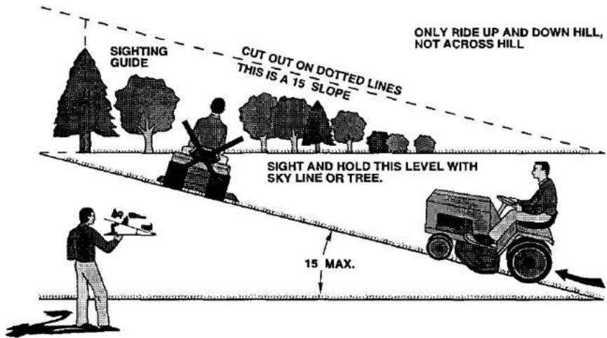

Operate your Tractor up and down the face of slopes (not greater than 15), never across the face. Make turns gradually to prevent tipping or loss of control. Exercise extreme caution when changing direction on slopes.
Get it fixed, at your home or ours!
For repair of major brand appliances in your own home ... no matter who made it, no matter who sold it!
1-800-4-MY-HOME®
(1-800-469-4663)
www.sears.com
Anytime, day or night
(U.S.A. and Canada)
www.sears.ca
For repair of carry-in products like vacuums, lawn equipment, and electronics, call for the nearest Sears Parts and Repair Center.
1-800-488-1222
Anytime, day or night (U.S.A. only)
www.seers.com
For the replacement parts, accessories and owner's manuals that you need to do-it-yourself, call Sears PartsDirect ^SM !
1-800-366-PART
(1-800-366-7278)
6 a.m.-11 p.m., 7 days a week
(U.S.A. only)
www.sears.com/partsdirect
To purchase or inquire about a Sears Service Agreement or Sears Maintenance Agreement:
1-800-827-6655 (U.S.A.)
7 a.m. - 5 p.m., CST, Mon. - Sat
1-800-361-6665 (Canada)
9 a.m.-8 p.m. EST, M-F, 4 p.m. Sat
© Sears, Roebuck and Co.
® Registered Trademark / ™ Trademark / ™ Service Mark of Sears, Roebuck and Co.
® Marca Registrada / ™ Marca de Fábrica / ™ Marca de Servicio do Soars, Roebuck and Co.
- TABLE OF CONTENTS
- WARRANTY
- LIMITED 90 DAY WARRANTY ON BATTERY
- SAFETY RULES
- GENERAL OPERATION
- SLOPE OPERATION
- DO:
- DO NOT:
- CHILDREN
- SERVICE
- REPAIR AGREEMENT
- CUSTOMER RESPONSIBILITIES
- UNASSEMBLED PARTS
- ASSEMBLY
- TOOLS REQUIRED FOR ASSEMBLY
- TO REMOVE TRACTOR FROM CARTON
- UNPACK CARTON
- BEFORE REMOVING TRACTOR FROM SKID
- ATTACH STEERING WHEEL
- HOW TO SET UP YOUR TRACTOR CHECK BATTERY
- INSTALL SEAT
- TO ROLL TRACTOR OFF SKID (See Operation section for location and function of controls)
- TO DRIVETRACTOR OFF SKID (See Operation section for location and function of controls)
- CHECK TIRE PRESSURE
- CHECK DECK LEVELNESS
- CHECK FOR PROPER POSITION OF ALL BELTS
- CHECK BRAKE SYSTEM
- √ CHECKLIST
- OPERATION
- KNOW YOUR TRACTOR
- READ THIS OWNER'S MANUAL AND SAFETY RULES BEFORE OPERATING YOUR TRACTOR
- HOW TO USE YOUR TRACTOR TO SET PARKING BRAKE
- STOPPING
- MOWER BLADES -
- GROUND DRIVE -
- ENGINE -
- TO USE THROTTLE CONTROL
- TO MOVE FORWARD AND BACK- WARD
- TO ADJUST MOWER CUTTING HEIGHT
- TO OPERATE MOWER
- TO OPERATE ON HILLS
- TO TRANSPORT
- TOWING CARTS AND OTHER ATTACHMENTS
- BEFORE STARTING THE ENGINE CHECK ENGINE OIL LEVEL
- ADD GASOLINE
- TO START ENGINE
- MOWING TIPS
- MAINTENANCE
- GENERAL RECOMMENDATIONS
- BEFORE EACH USE
- LUBRICATION CHART
- TRACTOR
- BRAKE OPERATION
- TIRES
- BLADE CARE
- BLADE REMOVAL
- TO SHARPEN BLADE
- BATTERY
- TO CLEAN BATTERY AND TERMINALS
- V-BELTS
- TRANSAXLE COOLING
- ENGINE
- LUBRICATION
- TO CHANGE ENGINE OIL
- CLEAN AIR SCREEN
- ENGINE COOLING FINS
- AIR FILTER
- TO SERVICE PRE-CLEANER
- TO SERVICE CARTRIDGE
- MUFFLER
- SPARK PLUGS
- IN-LINE FUEL FILTER
- CLEANING
- SERVICE AND ADJUSTMENTS
- CAUTION: BEFORE PERFORMING ANY SERVICE OR ADJUSTMENTS:
- TO REMOVE MOWER
- TO INSTALL MOWER
- SIDE-TO-SIDE ADJUSTMENT
- FRONT-TO-BACK ADJUSTMENT
- TO REPLACE MOWER BLADE DRIVE BELT
- BELT REMOVAL -
- BELT INSTALLATION -
- TO ADJUST BRAKE
- TO REPLACE MOTION DRIVE BELT
- TO ADJUST STEERING WHEEL ALIGNMENT
- FRONT WHEEL TOE-IN/CAMBER
- TO REMOVE WHEEL FOR REPAIRS
- TO START ENGINE WITH A WEAK BATTERY
- TO ATTACH JUMPER CABLES -
- REPLACING BATTERY
- TO REPLACE HEADLIGHT BULB
- INTERLOCKS AND RELAYS
- TO REMOVE HOOD AND GRILL ASSEMBLY
- TO ADJUST THROTTLE CONTROL CABLE
- TO ADJUST CARBURETOR
- PRELIMINARY SETTING -
- FINAL SETTING -
- ACCELERATION TEST
- STORAGE
- FUEL SYSTEM
- ENGINE OIL
- CYLINDER(S)
- OTHER
- SCHEMATIC
- TRACTOR - MODEL NUMBER 917.271531
- REPAIR PARTS
- TRACTOR -- MODEL NUMBER 917.271531
- TRACTOR – MODEL NUMBER 917.271531 CHASSIS AND ENCLOSURES
- TRACTOR -- MODEL NUMBER 917.271531 CHASSIS AND ENCLOSURES
- GROUND DRIVE
- STEERING
- KEY PART
- NO.
- DESCRIPTION
- SEAT ASSEMBLY
- LIFT ASSEMBLY
- TRACTOR - MODEL NUMBER 917.271531 LIFT ASSEMBLY
- MOWER DECK
- BRIGGS & STRATTON ENGINE-MODEL NUMBER 287707, TYPE NUMBER 1255-E3
- Get it fixed, at your home or ours!
Brand : Craftsman
Model : 917.271531
Category : Drill