
114 - Heating BROAN - Free user manual and instructions
Find the device manual for free 114 BROAN in PDF.


| Product Type | Kickspace Heater |
| Brand | Broan |
| Model | 114 |
| Color | White |
| Dimensions (Cutout) | 18-3/8" x 3-5/8" (467 mm x 92 mm) |
| Dimensions (Overall) | 19-3/8" L x 12-1/8" D x 3-5/8" H (492 mm x 308 mm x 92 mm) |
| Weight | Approx. 10 lbs (4.5 kg) |
| Power Supply | 240/208 VAC or 120 VAC (field convertible) |
| Wattage Options | 1500W at 240V, 1125W at 208V, 1500W or 750W at 120V |
| Amperage | 6.3A at 240V/120V (750W), 5.4A at 208V, 12.5A at 120V (1500W) |
| BTU/hr | Up to 5120 |
| Heating Element | Two elements (2 required) |
| Fan Type | Motor with blower wheel |
| Thermostat Options | Built-in optional (Model 90) or line voltage wall thermostat (Model 86W) |
| Safety Features | Thermal fuse, temperature limit switch, alarm light for overheating |
| Installation | Under counter/kickspace, horizontal position only |
| Warranty | 1 year limited |
| Lubrication | Permanent, no oiling needed |
| Cleaning | Monthly vacuum or wipe with soft cloth |
| Included Accessories | Jumper wire for 120V conversion, mounting brackets |
| Optional Accessories | Model 90 thermostat kit, Model 86W wall thermostat |
| Certifications | UL listed (assumed) |
Frequently Asked Questions - 114 BROAN
User questions about 114 BROAN
0 question about this device. Answer the ones you know or ask your own.
Ask a new question about this device
Download the instructions for your Heating in PDF format for free! Find your manual 114 - BROAN and take your electronic device back in hand. On this page are published all the documents necessary for the use of your device. 114 by BROAN.
USER MANUAL 114 BROAN
natural_image
Line drawing of a rectangular electronic device with ventilation grilles (no text or symbols)READ AND SAVE THESE INSTRUCTIONS
IMPORTANT INSTRUCTIONS
READ ALL INSTRUCTIONS BEFORE INSTALLING OR USING THIS HEATER.
To reduce the risk of fire, electric shock, or injury to persons, observe the following:
- Use this unit only in the manner intended by the manufacturer. If you have questions, contact the manufacturer at the address or telephone number listed in the warranty.
- Before servicing or cleaning unit, switch power off at service panel and lock the service disconnecting means to prevent power from being switched on accidentally. When the service disconnecting means cannot be locked, securely fasten a prominent warning device, such as a tag, to the service panel.
- Installation work and electrical wiring must be done by a qualified person(s) in accordance with all applicable codes and standards, including fire-rated construction codes and standards.
- When cutting or drilling into wall or ceiling, do not damage electrical wiring and other hidden utilities.
- This heater is hot when in use. To avoid burns, do not let bare skin touch hot surfaces. Keep combustible materials, such as furniture, pillows, bedding, papers, clothes, etc. and curtains at least 3 feet (0.9 m) from the front of the heater.
- Extreme caution is necessary when any heater is used by or near children or invalids and whenever the heater is left operating and unattended.
- Do not operate any heater after it malfunctions. Disconnect power at service panel and have heater inspected by a reputable electrician before reusing.
- Do not use outdoors.
- To disconnect heater, turn controls to off, and turn off power to heater circuit at main disconnect panel (or operate internal disconnect switch, if provided).
- Do not insert or allow foreign objects to enter any ventilation or exhaust opening, as this may cause an electric shock or fire, or damage the heater.
- To prevent a possible fire, do not block air intakes or exhaust in any manner.
- A heater has hot and arcing or sparking parts inside. Do not use it in areas where gasoline, paint, or flammable vapors or liquids are used or stored.
- Use this heater only as described in this manual. Any other use not recommended by the manufacturer may cause fire, electric shock, or injury to persons.
- To avoid electrical shock: Do not install unit in a tub or shower enclosure or any location where it may come in contact with water. Never place a switch where it can be reached from a tub or shower.
- Do not connect heater to dimmer switch or speed control.
- Do not install heater upside down or sideways. Heater must be located in the horizontal position.
- Do not recess louvered face of the heater more than three inches from the vertical face of any overhang (cabinet).
-
Provide this heater with a separate electrical circuit following directions under "Wiring" section.
-
This product is equipped with a thermostat which may start it automatically. Turn off power at service entrance before cleaning or servicing.
- This heater includes a visual alarm to warn that parts are getting excessively hot. If the alarm lights are activated, immediately turn the heater off and inspect for any objects on or adjacent to the heater that may cause high temperatures.
- This product must be grounded.
SAVE THESE INSTRUCTIONS
PLANNING
This heater is designed for installation in an enclosed space such as under a counter or kickspace to provide warm, gentle heat at the floor level. Reread Safety Notes 3 through 8 for guidelines in planning the installation.
The Model 114 is factory wired for 240/208 V.A.C. operation. It offers a choice of heat outputs and can be internally connected for multiple wattages at different voltages shown in the table below.
| VOLTS | WATTS | AMPS | BTU/HR |
| 240 | 1500 | 6.3 | 5120 |
| 208 | 1125 | 5.4 | 3840 |
| 120* | 1500 | 12.5 | 5120 |
| 120* | 750 | 6.3 | 2560 |
All ratings are 1-Phase, 60 Hertz.
*See "FIELD CONVERSION TO 120 V.A.C." section.
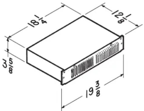
Cutout dimension: 18-3/8" x 3-5/8"
INSTALLATION
WARNING: To reduce the risk of fire, do not store or use gasoline or other flammable vapors and liquids in the vicinity of the heater.
CAUTION: High temperature, risk of fire, keep electrical cords, drapery, furnishings, and other combustibles at least 3 feet (0.9 m) from the front of the heater and away from the side and rear.
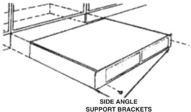
- Mark the intended mounting location in the base plate under the counter or kickspace, and remove required material to provide for easy insertion and removal of the heater cabinet.
- The unit will be secured in place with screws through the side angle support brackets. Provide adequate material behind side angle support for secure mounting.
FIELD CONVERSION TO 120 V.A.C.
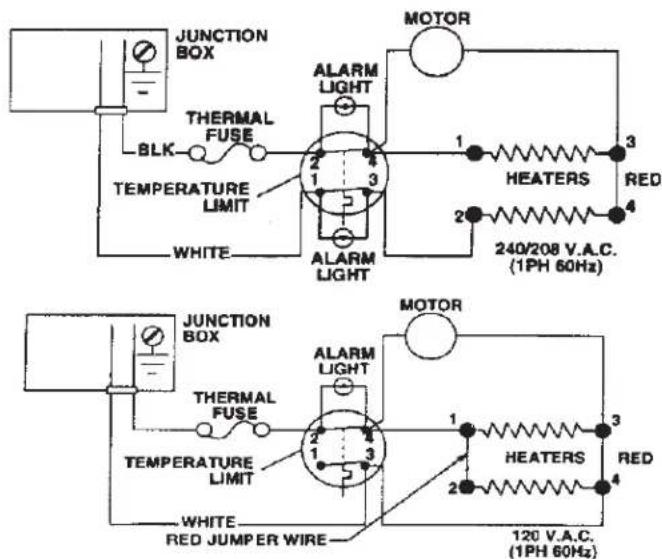
If a 120 V.A.C. circuit is to be used, make wiring changes as follows:
- Disconnect white wire from heater element terminal "2" and connect it to terminal "4." The heater will now operate at 120 V.A.C., 750W, 6.3A.
- For 120 V.A.C, 1500W, 12.5A operation, add the short red jumper wire (provided) between terminals "1" and "2".
- Remove alarm light wire leads from terminals "1" and "3" of the high temperature limit. Remove white wire lead from limit terminal "1" and reconnect at limit terminal "3". Secure wire leads with wire tie so there is no interference with unit operation.
NOTE: Terminal numbers are marked on the side of the blower housing, above the heater elements.
THERMOSTAT INSTALLATION
NOTE: The thermostat control circuit must be wired prior to the wiring of the heater unit.
This heater may be thermostatically controlled by either a line voltage wall-mounted thermostat (Model 86W), or an optional built-in thermostat accessory kit (Model 90). Model 90 thermostat kits are designed for easy installation with this heater. Instructions for installing thermostats are provided below and are also supplied with each thermostat kit.
OPTIONAL LINE VOLTAGE WALL-MOUNT THERMOSTAT
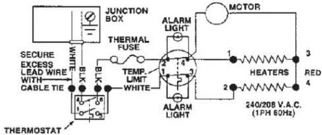
- Locate thermostat on an inside wall away from all drafts and approximately 4-5 feet above the floor.
- Route all wiring through the thermostat first and then to the heater.
OPTIONAL (MODEL 90) UNIT-MOUNT THERMOSTAT
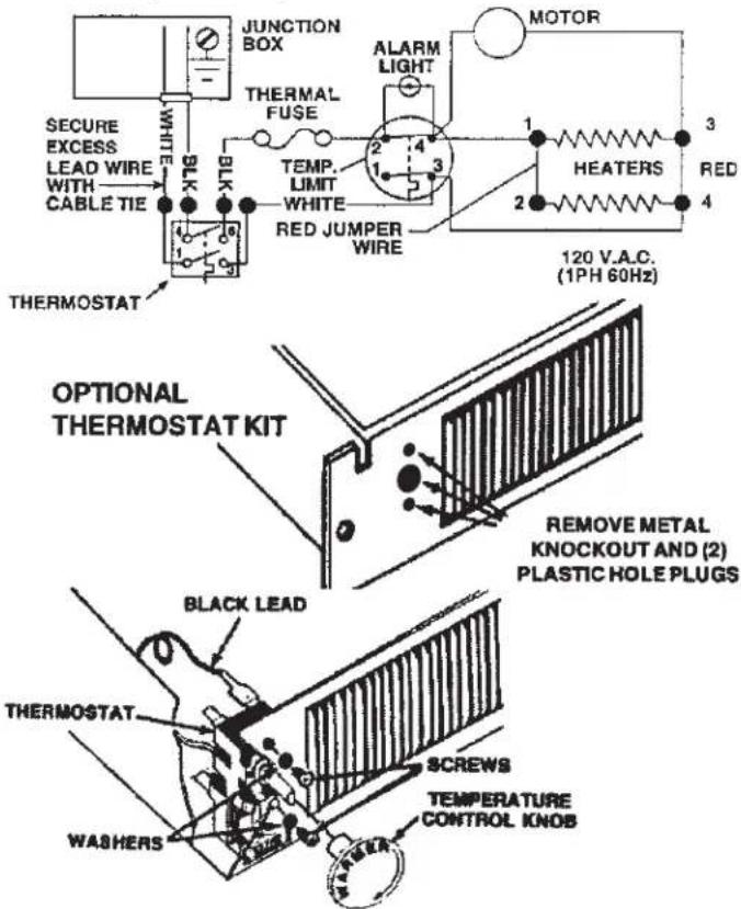
- Remove the top cover from the heater.
-
Remove the 5/8" knockout located on the left side of the front panel (use a screwdriver to remove the knockout). Also remove the two plastic hole plugs (see illustration).
-
Install thermostat from back side of front panel and fasten in place, from front, with two screws and washers provided (see illustrations).
- Attach temperature control knob by gently pushing it on to the thermostat shaft. Flats on shaft and knob must line up for proper installation (do not force control knob onto shaft).
- Remove black wire from thermal fuse and attach it to thermostat terminal marked "4".
- Remove white wire from temperature limit terminal marked "1" (Note: the other end of this wire is attached to incoming field wiring) and attach it to the thermostat terminal marked "1".
- Attach black thermostat wire to thermal fuse and white thermostat wire to the temperature limited marked "3".
WIRING
Installation work and electrical wiring must be done by a qualified person(s) in accordance with all applicable codes and standards, including fire-rated construction codes and standards.
natural_image
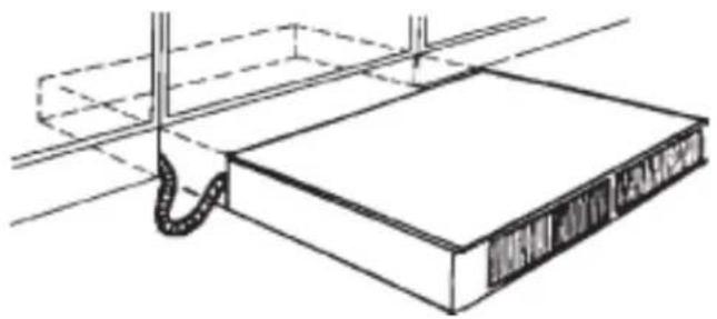
Technical line drawing of a mechanical assembly with a curved pipe and rectangular base (no text or symbols)- Run electrical power cable to installation location. Provide two feet of slack to allow heater to be pulled out far enough to remove top cover for cleaning or servicing.
NOTE: It is recommended that flexible conduit be used for field wiring to the unit to protect the wires from sharp objects or hazardous environments.
NOTE: Be sure supply voltage meets the equipment requirement. Refer to the rating plate, unit wiring diagram and specification table.
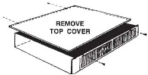
- Remove top cover for access to wiring box at rear of heater.
Page 3
-
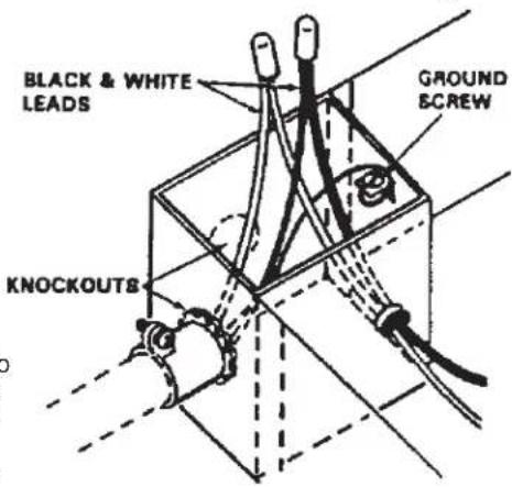
Remove one of the two knockouts and connect power cable to heater using appropriate connector. Allow at least six inches of wiring inside of wiring box.
-
Connect black to black, white to white and green (or bare wire) to ground screw, as shown. Tuck wires down inside the wiring box.
-
Replace top cover.
WARNING: Do not operate heater without top cover in place.
- Slide heater into place and secure to mounting surface.
OPERATION
Before using heater, make sure heater has been properly installed according to installation steps beginning with the "PLANNING" section on page 1.
- Turn thermostat counterclockwise to its lowest setting.
- Turn on power to circuit at service entrance.
- Turn thermostat clockwise. The heating element and fan should come on. Set thermostat to desired temperature level. During proper operation, the heater will cycle on and off periodically.
If heater does not come on:
- Return the thermostat to lowest setting.
- Shut off power at service entrance.
- Remove the top cover. Check for proper line voltage and reinspect wiring connections. Reread installation procedure making sure all steps were followed.
- Also check the thermal fuse. It may be open and need to be replaced. Consult the service parts list for the part number of a replacement fuse. Follow the procedure described in the last paragraph of the warranty when ordering replacement parts.
MAINTENANCE
The following maintenance and cleaning tasks can be performed by the user. All other servicing must be performed by an authorized technician. If you have any questions, please consult with our customer service department at: 800-558-1711.
LUBRICATION
The heater is permanently lubricated and never needs oiling or disassembly.
CLEANING
Clean heater once a month as follows:
- Turn off power at service panel.
- Make sure heating element is cool.
- Use a soft brush attachment to gently vacuum grille openings or wipe grille clean with a soft cloth.
- Restore power.
CAUTION: METAL AND ELECTRICAL PARTS SHOULD NEVER BE IMMERSED IN WATER.
WARRANTY
Limited Warranty
Warranty Period and Exclusions: Broan-NuTone LLC (the "Company") warrants to the original consumer purchaser of its product ("you") that the product (the "Product") will be free from material defects in the Product or its workmanship for a period of one (1) year from the date of original purchase.
The limited warranty period for any replacement parts provided by the Company and for any Products repaired or replaced under this limited warranty shall be the remainder of the original warranty period. This warranty does not cover speed controls, fluorescent lamp starters, tubes, halogen and incandescent bulbs, fuses, filters, ducts, roof caps, wall caps and other accessories for ducting that may be purchased separately and installed with the Product. This warranty also does not cover (a) normal maintenance and service, (b) normal wear and tear, (c) any Products or parts which have been subject to misuse, abuse, abnormal usage, negligence, accident, improper or insufficient maintenance, storage or repair (other than repair by the Company), (d) damage caused by faulty installation, or installation or use contrary to recommendations or instructions, (e) any Product that has been moved from its original point of installation, (f) damage caused by environmental or natural elements, (g) damage in transit, (h) natural wear of finish, (i) Products in commercial or nonresidential use, or (j) damage caused by fire, flood or other act of God. This warranty covers only Products sold to original consumers in the United States by the Company or U.S. distributors authorized by the Company.
This warranty supersedes all prior warranties and is not transferable from the original consumer purchaser.
No Other Warranties: This Limited Warranty contains the Company's sole obligation and your sole remedy for defective products. The foregoing warranties are exclusive and in lieu of any other warranties, express or implied. THE COMPANY DISCLAIMS AND EXCLUDES ALL OTHER EXPRESS WARRANTIES, AND DISCLAIMS AND EXCLUDES ALL WARRANTIES IMPLIED BY LAW, INCLUDING WITHOUT LIMITATION THOSE OF MERCHANTABILITY AND FITNESS FOR A PARTICULAR PURPOSE. To the extent that applicable law prohibits the exclusion of implied warranties, the duration of any applicable implied warranty is limited to the period specified for the express warranty above. Some states do not allow limitations on how long an implied warranty lasts, so the above limitation may not apply to you. Any oral or written description of the Product is for the sole purpose of identifying it and shall not be construed as an express warranty.
Whenever possible, each provision of this Limited Warranty shall be interpreted in such manner as to be effective and valid under applicable law, but if any provision is held to be prohibited or invalid, such provision shall be ineffective only to the extent of such prohibition or invalidity, without invalidating the remainder of such provision or the other remaining provisions of the Limited Warranty.
Remedy: During the applicable limited warranty period, the Company will, at its option, provide replacement parts for, or repair or replace, without charge, any Product or part thereof, to the extent the Company finds it to be covered by and in breach of this limited warranty under normal use and service. The Company will ship the repaired or replaced Product or replacement parts to you at no charge. You are responsible for all costs for removal, reinstallation and shipping, insurance or other freight charges incurred in the shipment of the Product or part to the Company. If you must send the Product or part to the Company, as instructed by the Company, you must properly pack the Product or part—the Company is not responsible for damage in transit. The Company reserves the right to utilize reconditioned, refurbished, repaired or remanufactured Products or parts in the warranty repair or replacement process. Such Products and parts will be comparable in function and performance to an original Product or part and warranted for the remainder of the original warranty period.
Exclusion of Damages: THE COMPANY'S OBLIGATION TO PROVIDE REPLACEMENT PARTS, OR REPAIR OR REPLACE, AT THE COMPANY'S OPTION, SHALL BE YOUR SOLE AND EXCLUSIVE REMEDY UNDER THIS LIMITED WARRANTY AND THE COMPANY'S SOLE AND EXCLUSIVE OBLIGATION. THE COMPANY SHALL NOT BE LIABLE FOR INCIDENTAL, INDIRECT, CONSEQUENTIAL OR SPECIAL DAMAGES ARISING OUT OF OR IN CONNECTION WITH THE PRODUCT, ITS USE OR PERFORMANCE.
Some states do not allow the exclusion or limitation of incidental or consequential damages, so the above limitation or exclusion may not apply to you. This warranty gives you specific legal rights, and you may also have other rights, which vary from state to state.
This warranty covers only replacement or repair of defective Products or parts thereof at the Company's main facility and does not include the cost of field service travel and living expenses.
Any assistance the Company provides to or procures for you outside the terms, limitations or exclusions of this limited warranty will not constitute a waiver of such terms, limitations or exclusions, nor will such assistance extend or revive the warranty.
The Company will not reimburse you for any expenses incurred by you in repairing or replacing any defective Product, except for those incurred with the Company's prior written permission.
How to Obtain Warranty Service: To qualify for warranty service, you must (a) notify the Company at the address or telephone number stated below within seven (7) days of discovering the covered defect, (b) give the model number and part identification and (c) describe the nature of any defect in the Product or part. At the time of requesting warranty service, you must present evidence of the original purchase date. If you cannot provide a copy of the original written limited warranty, then the terms of the Company's most current written limited warranty for your particular product will control. The most current limited written warranties for the Company's products can be found at www.broan.com.
Broan 926 West State Street, Hartford, WI 53027
www.broan.com 800-558-1711
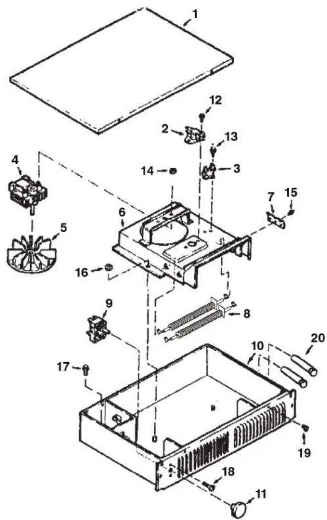
SERVICE PARTS
| KEYNO. | PARTNUMBER | PART DESCRIPTION |
| 1 | 99522899 | Cover (White) |
| 2 | 99522400 | Cycling Thermal Overload Limit Switch |
| 3 | 99521763 | Thermal Fuse |
| 4 | 99521765 | Motor |
| 5 | 99020130 | Blower Wheel |
| 6 | 99521760 | Motor Plate |
| 7 | 99521761 | Element Retainer |
| 8 | 99271288 | Heater Element (2 Required) |
| 9 | 99521767 | Thermostat (Optional) |
| 10 | --- | Housing (White) |
| 11 | 99521769 | Knob (Optional) |
| 12 | * | Screw, 6-20 x 1/4 Slotted Hex Head(2 Required) |
| 13 | * | Screw, 6-20 x 3/8 Slotted HeadHead AB Pt. |
| 14 | * | Nut, 6-32 Hex Keps (2 Required) |
| 15 | * | Screw, 10-16 x 3/8 Slotted HeadHead AB Pt. |
| 16 | * | Nut, 10-32 Hex Keps (2 Required) |
| 17 | * | Screw, 10-32 x 1/2 Slotted HeadHead Type F |
| 18 | * | Screw, 6-32 x 3/4 Phillips Pan Head(2 Required) (Optional) |
| 19 | * | Screw, 8-18 x 1/4 Slotted Pan Head(4 Required) |
| 20 | 99522782 | Alarm Light |
* Standard Hardware. May be purchased locally.
SERVICE PARTS
CALEFACTOR PARA ESPACIOS BAJO GABINETES
natural_image
Line drawing of a rectangular electronic device with ventilation slots and mounting feet (no text or symbols)Página 7
LEA Y CONSERVE ESTAS INSTRUCCIONES
INSTRUCCIONES IMPORTANTES
LEA TODAS LAS INSTRUCCIONES ANTES DE INSTALAR O USAR ESTE CALENTADOR.
natural_image
Diagram of a ceiling-mounted device with a coiled cable and ventilation duct (no text or symbols)Broan 926 West State Street, Hartford, WI 53027
www.broan.com 800-558-1711
PIEZAS DE REPUESTO
| CLAVE No. | NÚMERO DE PIEZA | DESCRIPCIÓN DE LA PIEZA |
| 1 | 99522899 | Cubierta (blanca) |
| 2 | 99522400 | Interruptor limitador de sobrecarga térmica (cíclico) |
| 3 | 99521763 | Fusible térmico |
| 4 | 99521765 | Motor |
| 5 | 99020130 | Rueda del soplador |
| 6 | 99521760 | Placa del motor |
| 7 | 99521761 | Retenedor del elemento |
| 8 | 99271288 | Elemento calefactor (se requieren 2) |
| 9 | 99521767 | Termostato (opcional) |
| 10 | --- Cubierta (blanca) | |
| 11 | 99521769 | Perilla (opcional) |
| 12 | * | Tornillo, cabeza hexagonal ranurada 6-20 × 1/4 (se requieren 2) |
| 13 | * | Tornillo, cabeza ranurada 6-20 × 3/8 AB Pt. |
| 14 | * | Tuerca, llaves hexagonales 6-32 (se requieren 2) |
| 15 | * | Tornillo, cabeza ranurada 10-16 × 3/8 AB Pt. |
| 16 | * | Tuerca, llaves hexagonales 10-32 (se requieren 2) |
| 17 | * | Tornillo, cabeza ranurada 10-32 × 1/2 tipo F |
| 18 | * | Tornillo, cabeza plana Phillips 6-32 × 3/4 (se requieren 2) (opcional) |
| 19 | * | Tornillo, cabeza plana ranurada 8-18 × 1/4 (se requieren 4) |
| 20 | 99522782 | Luz de alarma |
- READ AND SAVE THESE INSTRUCTIONS
- IMPORTANT INSTRUCTIONS
- READ ALL INSTRUCTIONS BEFORE INSTALLING OR USING THIS HEATER.
- SAVE THESE INSTRUCTIONS
- PLANNING
- INSTALLATION
- THERMOSTAT INSTALLATION
- WIRING
- OPERATION
- MAINTENANCE
- LUBRICATION
- CLEANING
- WARRANTY
- Limited Warranty
- CALEFACTOR PARA ESPACIOS BAJO GABINETES
- LEA Y CONSERVE ESTAS INSTRUCCIONES
- INSTRUCCIONES IMPORTANTES
- LEA TODAS LAS INSTRUCCIONES ANTES DE INSTALAR O USAR ESTE CALENTADOR.
Brand : BROAN
Model : 114
Category : Heating