
194 - Heating BROAN - Free user manual and instructions
Find the device manual for free 194 BROAN in PDF.


| Product Type | Heating appliance |
| Brand | Broan |
| Model | 194 |
| Power Supply | 120 V, 60 Hz |
| Maximum Power | 1500 W |
| Heating Element | Fan-forced electric heater |
| Number of Heat Settings | 2 (Low and High) |
| Fan-Only Mode | Yes |
| Thermostat | Adjustable bimetallic thermostat |
| Dimensions (W x H x D) | 10 x 8 x 6 inches (approx.) |
| Net Weight | 3.5 lbs (approx.) |
| Safety Features | Automatic thermal overheat protection |
| Mounting Type | Portable, free-standing |
| Color | White or beige (typical) |
| Control Type | Manual rotary knobs |
| Air Flow Direction | Fixed louver |
| Noise Level | Low (fan) |
| Maintenance | Unplug and clean exterior with damp cloth; replace fuse if needed |
| Repairability | User-replaceable fuse; professional service for other repairs |
| Certifications | UL listed or equivalent |
Frequently Asked Questions - 194 BROAN
User questions about 194 BROAN
0 question about this device. Answer the ones you know or ask your own.
Ask a new question about this device
Download the instructions for your Heating in PDF format for free! Find your manual 194 - BROAN and take your electronic device back in hand. On this page are published all the documents necessary for the use of your device. 194 by BROAN.
USER MANUAL 194 BROAN
READ AND SAVE THESE INSTRUCTIONS
IMPORTANT INSTRUCTIONS
READ ALL INSTRUCTIONS BEFORE INSTALLING OR USING THIS HEATER.
To reduce the risk of fire, electric shock, or injury to persons, observe the following:
- Use this unit only in the manner intended by the manufacturer. If you have questions, contact the manufacturer at the address or telephone number listed in the warranty.
- Before servicing or cleaning unit, switch power off at service panel and lock the service disconnecting means to prevent power from being switched on accidentally. When the service disconnecting means cannot be locked, securely fasten a prominent warning device, such as a tag, to the service panel.
- Installation work and electrical wiring must be done by a qualified person(s) in accordance with all applicable codes and standards, including fire-rated construction codes and standards.
- When cutting or drilling into wall or ceiling, do not damage electrical wiring and other hidden utilities.
- This heater is hot when in use. To avoid burns, do not let bare skin touch hot surfaces. Keep combustible materials, such as furniture, pillows, bedding, papers, clothes, etc. and curtains at least 3 feet (0.9 m) from the front of the heater.
- Extreme caution is necessary when any heater is used by or near children or invalids and whenever the heater is left operating and unattended.
- Do not operate any heater after it malfunctions. Disconnect power at service panel and have heater inspected by a reputable electrician before reusing.
-
Do not use outdoors.
-
To disconnect heater, turn controls to off, and turn off power to heater circuit at main disconnect panel (or operate internal disconnect switch, if provided).
- Do not insert or allow foreign objects to enter any ventilation or exhaust opening, as this may cause an electric shock or fire, or damage the heater.
- To prevent a possible fire, do not block air intakes or exhaust in any manner.
- A heater has hot and arcing or sparking parts inside. Do not use it in areas where gasoline, paint, or flammable vapors or liquids are used or stored.
- Use this heater only as described in this manual. Any other use not recommended by the manufacturer may cause fire, electric shock, or injury to persons.
- Install heater at least 12 inches from floor or any adjacent wall.
- To avoid electrical shock: Do not install unit in a tub or shower enclosure or any location where it may come in contact with water. Never place a switch where it can be reached from a tub or shower.
- This product may ONLY be installed vertically in a wall. Do not mount in any other position.
- Do not connect heater to dimmer switch or speed control.
- This product must be grounded.
SAVE THESE INSTRUCTIONS
PLANNING
This heater is intended to be used to supply supplemental heat from a wall location in new or existing construction.
Choose a location where edge of heater will be at least 12" from the floor or any adjacent vertical surface.
The heater can be operated using its built-in thermostat or a remote thermostat (such as the Model 86W Line-Voltage thermostat or an appropriate low-voltage thermostat and transformer/relay). The Model 85 Kit is available for surface-mount applications. Purchase these accessories separately.
Plan to supply the heater with proper line voltage and appropriate power cable.
NOTE: Power can be tapped from a nearby circuit depending on the heater wattage required and the amperage rating of the circuit.
Heater can be converted to half-wattage to avoid overloading such circuits.
| MODEL | VOLTS | AMPS | WATTS | BTU/HR |
| 192 | 240 | 8.33/4.17 | 2000/1000 | 6827/3413 |
| 194 | 240 | 12.50/6.25 | 3000/1500 | 10240/5120 |
| 198 | 240 | 16.67/8.33 | 4000/2000 | 13653/6827 |
Bold ratings are factory wired.
See "OPTIONAL WIRING CONVERSIONS" section for wattage conversion instructions.
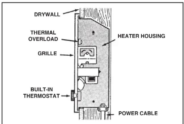
Follow these basic steps when installing this heater:
1) Nail housing to studs.
2) Connect power cable.
3) Fasten heater assembly and grille to housing.
INSTALLATION
WARNING: To reduce the risk of fire, do not store or use gasoline or other flammable vapors and liquids in the vicinity of the heater.
CAUTION: High temperature, risk of fire, keep electrical cords, drapery, furnishings, and other combustibles at least 3 feet (0.9 m) from the front of the heater and away from the side and rear.
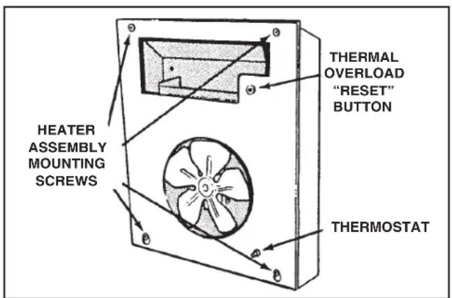
- Remove heater assembly from housing. Take out the four (4) screws shown and set heater assembly aside.
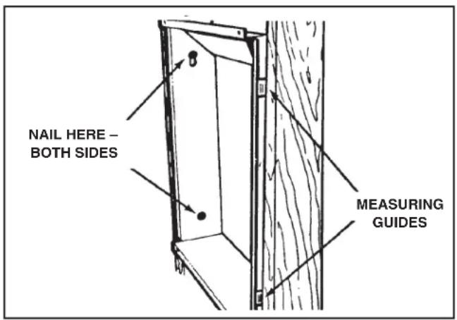
- Attach housing to wall studs.
NOTE: Locate housing at least 12" from floor on any adjacent walls.
Use the measuring guides on the sides of housing to position housing so that it will be flush with finished wall. Nail the housing to studs through the hole and slot on both sides of housing.
NOTE: In 24"-on-center stud construction, framing in between studs is necessary.
WIRING
Installation work and electrical wiring must be done by a qualified person(s) in accordance with all applicable codes and standards, including fire-rated construction codes and standards.
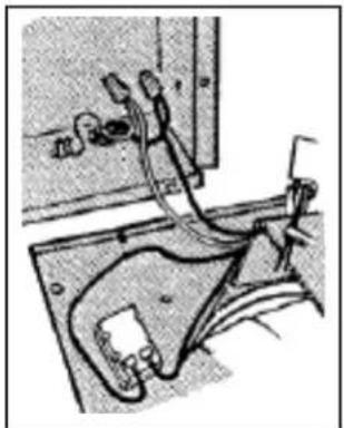
- Connect power cable to housing. Attach electrical power cable to housing using appropriate connector. Allow 6" of wire inside housing.
- Wire the heater assembly. Connect wires from heater assembly to power cable wires. Follow wiring diagram.
If heater is wired direct, use the built-in thermostat for temperature control.
natural_image
Technical line drawing of a mechanical assembly with no visible text or symbols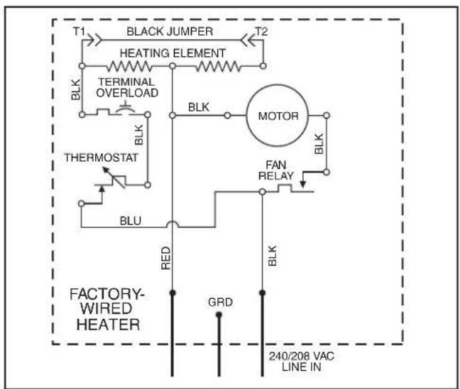
OPTIONAL WIRING CONVERSIONS
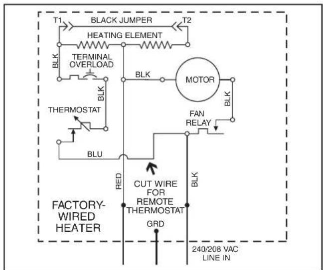
When using a separate wall control, simply turn the heater's built-in thermostat to its highest setting. There is no need to disconnect the built-in thermostat:
a) Turn built-in thermostat to highest setting.
b) Remove knob.
c) Fasten security cover to grille.
LINE-VOLTAGE THERMOSTAT
flowchart
graph TD
    A["BLACK JUMPER"] --> B["HEATING ELEMENT"]
    B --> C["TERMINAL OVERLOAD"]
    C --> D["BLK"]
    D --> E["MOTOR"]
    E --> F["FAN RELAY"]
    F --> G["BLK"]
    G --> H["CUT WIRE FOR REMOTE THERMOSTAT"]
    H --> I["GRD"]
    I --> J["240/208 VAC LINE IN"]
    K["BLU"] --> L["TERMOSTAT"]
    M["RED"] --> N["FACTORY-WIRED HEATER"]
    O["BLK"] --> P["BLK"]
If wall-mounted control is desired, use the Model 86W Line-Voltage Thermostat. Purchase thermostat separately.
Cut blue wire. Strip 12 " of insulation from each end. Connect wires from wall control to each stripped wire.
If wall-mounted control is desired, use a transformer/relay with an appropriate low-voltage thermostat (purchase separately). Follow the mounting and wiring instructions packed with the controls.
HALF-WATTAGE CONVERSION
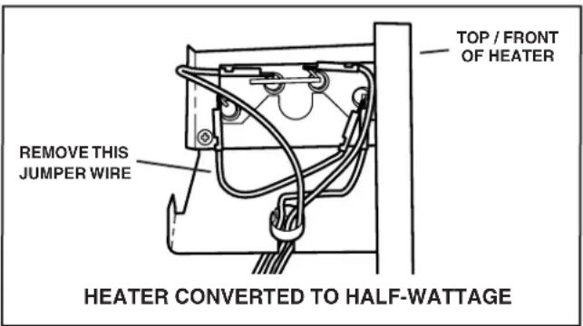
The heater will produce less heat and use less electricity if converted to half-wattage. Remove the black jumper wire from the heating element and discard wire.
COMPLETE THE INSTALLATION
- Install housing mask. A housing mask has been provided to keep construction dust, drywall spray, paint, etc., from damaging the heater. Bend the flap on the mask and push it into the heater housing.
NOTE: Mask can be put into place before or after heater assembly is reinstalled. Remove mask before operation. - Reinstall heater assembly. Secure heater assembly to housing with four (4) screws. Check thermal overload button marked "RESET". Heater will not operate unless this button is depressed.
natural_image
Technical line drawing of a door panel with internal compartments and a handle (no text or symbols)-
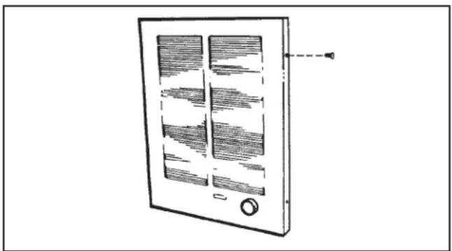
Install grille. Place grille over heater and attach with four (4) screws. Push knob onto thermostat stem.
-
Attach security cover to grille (optional). When heater is installed in a public area without a separate wall control, it is recommended that:
a) Built-in thermostat be set to desired temperature level.
b) Thermostat knob be removed.
c) Security cover be attached to grille with two (2) screws, provided.
- Check operation. Turn on power at service entrance. Turn thermostat to its highest setting and make sure heating element and blower come on. Then turn it to its lowest setting and make sure element and blower shut off.
NOTE: The fan delay prevents the fan from coming on until the element is hot. Likewise, it keeps the fan running until the element cools down.
OPERATION
Before using heater, make sure heater has been properly installed according to installation steps under "INSTALLATION" on page 3.
The heater can be operated using its built-in thermostat or a remote thermostat (such as the Model 86W Line-Voltage thermostat or an appropriate low-voltage thermostat and transformer/relay). The Model 85 Kit is available for surface-mount applications. Purchase these accessories separately.
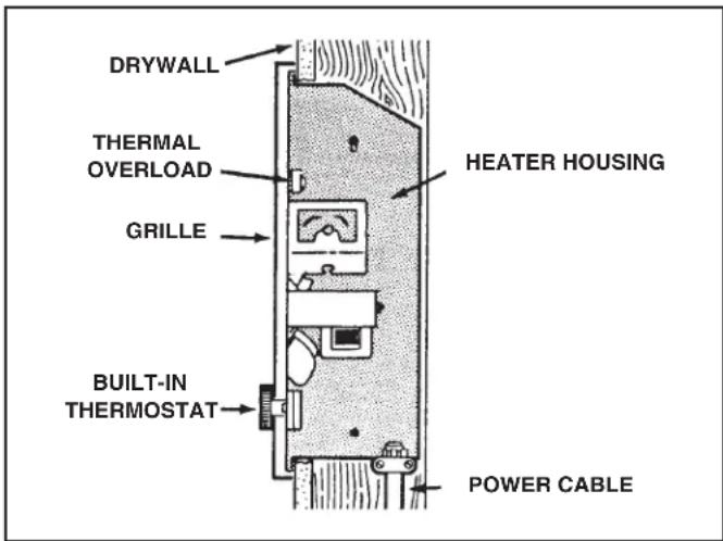
THERMAL OVERLOAD PROTECTOR
Your heater is equipped with a manual-reset thermal overload protector. If heater fails to operate when thermostat is turned to its highest setting:
1) Turn off power at service entrance.
2) Remove knob and grille.
3) Press button marked "RESET".
This type of device is particularly useful (compared to automatic reset devices) because it encourages the user to find and correct the cause of overheating unit when resetting the protector.
TO AVOID PROPERTY DAMAGE WHEN USING THIS HEATER TO PREVENT FREEZE-UPS:
Make sure heater functions properly before leaving unattended. A tripped protector will prevent the heater from operating.
MAINTENANCE
The following maintenance and cleaning tasks can be performed by the user. All other servicing must be performed by an authorized technician If you have any questions, please consult with our customer service department at: 800-558-1711.
LUBRICATION
The heater is permanently lubricated and never needs oiling or disassembly.
CLEANING
Clean heater once a month as follows:
- Turn off power at service panel.
- Make sure heating element is cool.
- Use a soft brush attachment to gently vacuum grille openings or wipe grille clean with a soft cloth.
- Restore power.
CAUTION: METAL AND ELECTRICAL PARTS SHOULD NEVER BE IMMERSED IN WATER.
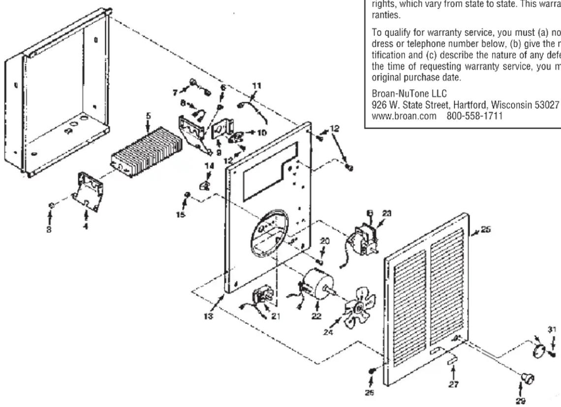
SERVICE PARTS
| KEYNO. N | PARTUMBER PART DESCRIPTION |
| 3 9903 | 0190 Fan Delay |
| 4 9800 | 6989 Element Bracket (2 Required) |
| 5 9927 | 1155 Heating Element (Model 192) |
| 99270 | 723 Heating Element (Model 194) |
| 99270 | 724 Heating Element (Model 198) |
| 6 | 99400061 Bushing |
| 7 9700 | 8688 Black Wire Assembly (29-1/2") |
| 8 9700 | 8690 Black Jumper Wire |
| 9 | * Thermal Overload Bracket |
| 10 | * Thermal Overload |
| 11 | 97008692 Red Power Wire |
| 12 | 99150491 Screw, 8-18 x 3/8 Ph. Pan Head(14 Required) |
| 13 | 97008683 Partition Plate Assembly |
| 14 | 93270619 Wire Clamp (3 Required) |
| 15 | 99260425 Nut, 8-32 Hex Keps (2 Required) |
| 20 | 99160350 Screw, 6-32 x 1/4 Ph. Pan Head(2 Required) |
| 21 | 99030324 Thermostat |
| 22 | 99080251 Motor (Model 198) |
| 23 | 99080249 Motor (Models 192 & 194) |
| 24 | 99020255 Fan Blade |
| 25 | 97013822 Grille |
| 26 | 99150478 Screw, 8-18 x 3/8 PH Truss Hd.(4 Required) |
| 27 | 99090683 Grille Logo |
| 29 | 99360136 Knob |
| 30 | 99110687 Security Cover |
| 31 | 93150462 Screw, 8-18 x 5/8 Oval Head (2 Required) |
| * | 97013945 Assembly, Thermal Overload (Includes Key Nos. 9, 10, & 12 (2)) |
WARRANTY
BROAN-NUTONE ONE YEAR LIMITED WARRANTY
Broan-NuTone warrants to the original consumer purchaser of its products that such products will be free from defects in materials or workmanship for a period of one year from the date of original purchase. THERE ARE NO OTHER WARRANTIES, EXPRESS OR IMPLIED, INCLUDING, BUT NOT LIMITED TO, IMPLIED WARRANTIES OF MERCHANTABILITY OR FITNESS FOR A PARTICULAR PURPOSE.
During this one-year period, Broan-NuTone will, at its option, repair or replace, without charge, any product or part which is found to be defective under normal use and service.
THIS WARRANTY DOES NOT EXTEND TO FLUORESCENT LAMP STARTERS, TUBES, HALOGEN AND INCANDESCENT BULBS, FUSES, FILTERS, DUCTS, ROOF CAPS, WALL CAPS AND OTHER ACCESSORIES FOR DUCTING. This warranty does not cover (a) normal maintenance and service or (b) any products or parts which have been subject to misuse, negligence, accident, improper maintenance or repair (other than by Broan-NuTone), faulty installation or installation contrary to recommended installation instructions.
The duration of any implied warranty is limited to the one-year period as specified for the express warranty. Some states do not allow limitation on how long an implied warranty lasts, so the above limitation may not apply to you.
BROAN-NUTONE'S OBLIGATION TO REPAIR OR REPLACE, AT BROAN-NUTONE'S OPTION, SHALL BE THE PURCHASER'S SOLE AND EXCLUSIVE REMEDY UNDER THIS WARRANTY. BROAN-NUTONE SHALL NOT BE LIABLE FOR INCIDENTAL, CONSEQUENTIAL OR SPECIAL DAMAGES ARISING OUT OF OR IN CONNECTION WITH PRODUCT USE OR PERFORMANCE. Some states do not allow the exclusion or limitation of incidental or consequential damages, so the above limitation or exclusion may not apply to you.
This warranty gives you specific legal rights, and you may also have other rights, which vary from state to state. This warranty supersedes all prior warranties.
To qualify for warranty service, you must (a) notify Broan-NuTone at the address or telephone number below, (b) give the model number and part identification and (c) describe the nature of any defect in the product or part. At the time of requesting warranty service, you must present evidence of the original purchase date.
Broan-NuTone LLC
926 W. State Street, Hartford. Wisconsin 53027
www.broan.com 800-558-1711
Product specifications
subject to change
without notice.
99045869A
natural_image
Technical line drawing of a mechanical assembly with no visible text or symbols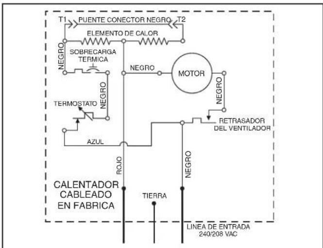
CONVERSIONES DE CABLEADO OPCIONAL
natural_image
Technical line drawing of a door panel with handle and mounting bracket (no text or symbols)926 W. State Street, Hartford, Wisconsin 53027
www.broan.com 800-558-1711
- READ AND SAVE THESE INSTRUCTIONS
- IMPORTANT INSTRUCTIONS
- READ ALL INSTRUCTIONS BEFORE INSTALLING OR USING THIS HEATER.
- SAVE THESE INSTRUCTIONS
- PLANNING
- INSTALLATION
- WIRING
- OPTIONAL WIRING CONVERSIONS
- HALF-WATTAGE CONVERSION
- COMPLETE THE INSTALLATION
- OPERATION
- THERMAL OVERLOAD PROTECTOR
- TO AVOID PROPERTY DAMAGE WHEN USING THIS HEATER TO PREVENT FREEZE-UPS:
- MAINTENANCE
- LUBRICATION
- CLEANING
- WARRANTY
- BROAN-NUTONE ONE YEAR LIMITED WARRANTY
- CONVERSIONES DE CABLEADO OPCIONAL
Brand : BROAN
Model : 194
Category : Heating