
AA35G - Receiver ATLAS - Free user manual and instructions
Find the device manual for free AA35G ATLAS in PDF.


| Product Type | Receiver |
| Brand | ATLAS |
| Model | AA35G |
| Frequency Range | FM: 87.5-108 MHz; AM: 530-1710 kHz |
| Dimensions (WxHxD) | 430 x 90 x 280 mm |
| Weight | 3.5 kg |
| Power Supply | AC 110-240V, 50/60Hz; DC 12V |
| Power Consumption | 25 W |
| Audio Output Power | 2 x 15 W RMS |
| Inputs | AUX (RCA), USB, SD card |
| Outputs | Speaker terminals (4-16 Ω), Headphone 3.5mm |
| Tuner Presets | 30 FM / 20 AM |
| Display | LCD with backlight |
| Remote Control | Included (IR) |
| Main Functions | Radio tuner, amplifier, USB/SD playback, alarm clock, sleep timer |
| Cleaning | Wipe with dry soft cloth; avoid liquids |
| Safety Features | Overload protection, auto standby after 30 min |
| Spare Parts | Remote control, power cord, antenna (available from ATLAS service) |
| Repairability | Designed for easy access; service manual available |
| General Info | For indoor use only; operating temp 0-40°C |
Frequently Asked Questions - AA35G ATLAS
User questions about AA35G ATLAS
0 question about this device. Answer the ones you know or ask your own.
Ask a new question about this device
Download the instructions for your Receiver in PDF format for free! Find your manual AA35G - ATLAS and take your electronic device back in hand. On this page are published all the documents necessary for the use of your device. AA35G by ATLAS.
USER MANUAL AA35G ATLAS
AA35G & AA60G Commercial Mixer Amplifier
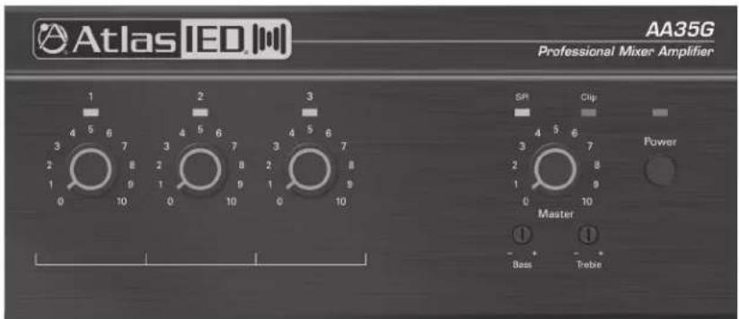

AA35G / AA60G
Owner's Manual
Table of Contents
| Important Safety Instructions | 3 |
| Introduction | 5 |
| Key Features | 5 |
| Applications | 5 |
| Front Panel Description | 6 |
| Rear Panel Description | 7 |
| Installation | 8 |
| Rack Mounting | 8 |
| Input Wire and Connections | 9 |
| Output Wire Connections | 10 |
| Zone 2 Output Connections | 10 |
| Wiring the System | 11 |
| Phantom Power | 11 |
| Operation | 12 |
| Troubleshooting | 13 |
| Specifications | 14 |
| Warranty | 16 |
AA35G / AA60G
Owner's Manual
Important Safety Instructions

ATTENTION

RISQUE DE CHOC ÉLECTRIQUE
- NE PAS OUVRIR,

CAUTION
WARNING
TO REDUCE THE RISK OF FIRE OR ELECTRIC SHOCK DO NOT EXPOSE THIS APPLIANCE TO RAIN OR MOISTURE.
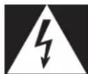
The lightning flash with arrowhead symbol within an equilateral triangle, is intended to alert the user to the presence of uninsulated “dangerous voltage” within the product’s enclosure that may be of sufficient magnitude to constitute a risk of electric shock to persons.

The exclamation point within an equilateral triangle is intended to alert the user to the presence of important operating and maintenance (servicing) instructions in the literature accompanying the product.
- Read these instructions.
- Keep these instructions.
- Pay close attention to all warnings.
- Follow all instructions.
- Do not use this device near liquids.
- Clean only with a dry cloth.
- Do not block any ventilation openings. Install in accordance with the manufacturer's instructions.
- Do not install near any heat sources such as radiators, heat registers, stoves, or other device (including amplifiers) that produce heat.
- Do not defeat the safety purpose of the polarized or grounding-type plug. A polarized plug has two blades with one wider than the other. A grounding type plug has two blades and a third grounding prong. The wide blade or the third prong are provided for your safety. If the provided plug does not fit into your outlet, consult an electrician for replacement of the obsolete outlet.
- Protect the power cord from being walked on or pinched particularly at plugs, convenience receptacles, and the point where they exit from the device.
- Only use attachments/accessories specified by the manufacturer.
- Use only with the cart, stand, tripod, bracket, or table specified by the manufacturer, or sold with the device. When a cart is used, use caution when moving the cart/device combination to avoid injury from tip-over.
- Unplug this device during lightning storms or when unused for long periods of time.
- Refer all servicing to qualified service personnel. Servicing is required when the device has been damaged in any way, such as power-supply cord or plug is damaged, liquid has been spilled, or objects have fallen into the device, the device has been exposed to rain or moisture, does not operate normally, or has been dropped.
- WARNING: To reduce the risk of fire or electric shock, do not expose this apparatus to rain or moisture.
- The apparatus shall not be exposed to dripping or splashing and no objects filled with liquids, such as vases, shall be placed on apparatus.
- The mains plug is used as a disconnect device. The mains plug of the apparatus should not be obstructed OR should be easily accessed during intended use. To completely disconnect the power input, the mains plug of apparatus shall be disconnected from the mains.
- This product shall be connected to a mains socket outlet with a protective earthing connection.
AA35G / AA60G
Owner's Manual
NING - When The Device Is In Use
- WARNING: For the terminals marked with symbol of may be of sufficient magnitude to constitute a risk of electric shock. The external wiring connected to the terminals requires installation by an instructed person or the used of ready-made leads or cords.
- WARNING: The apparatus shall not be exposed to dripping or splashing and that objects filled with liquids, such as vases, shall not be placed on apparatus.
- WARNING: The mains plug is used as disconnect device, the disconnect device shall remain readily operable.
- To prevent electric shock, do not remove the product cover as there are high voltage components inside. Refer all servicing to AtlasIED.
-
Should any of the following irregularities occur during use, immediately switch off the power, disconnect the power cord from the AC outlet and contact AtlasIED. Do not to attempt to continue operation with the product as this may cause fire or electric shock:
-
Smoke or strange smell coming from the unit.
- If the product falls or the case is damaged.
- If water or any metallic objects falls into the product.
- If the power supply cord is damaged in any way.
-
If the unit is malfunctioning.
-
Do not insert or drop metallic objects or flammable materials into the ventilation holes of the product's cover, as this may result in electric shock or fire.
• Do not place any containers with liquid or metallic objects on the top of the product. If any liquid spills into the unit, fire or electric shock may result. - Never operate this product or touch the power supply cord during an electrical storm, electric shock may result.
- Never exceed the power rating on the product when connecting equipment. Fire and/or property damage may result.
• Operate the product only with the voltage specified on the unit. Fire and/or electric shock may result if a higher voltage is used. - Do not modify, kink, or cut the power cord. Do not place the power cord in close proximity to heaters and do not place heavy objects on the power cord, including the product itself, doing so may result in fire or electrical shock.
- Ensure that the safety ground terminal is connected to a proper ground. Never connect the ground to a gas pipe as a catastrophic disaster may result.
- Be sure the installation of the product is stable, avoid slanted surfaces as the product may fall and cause injury or property damage.

TION - When Installing The Product
- Plugging in or unplugging the power cord with wet hands may result in electric shock.
- Never move the unit with the power cord plugged into the wall, as damage to the power cord may result.
- When unplugging the cord from the wall, grasp the plug, NOT the cord.
- Never install this product in humid or dusty locations, nor in direct sunlight, near sources of heat, or in areas where sooty smoke or steam are present. Fire and electric shock may result.
- Keep all sides of the unit at least 3 ^1/2 " away from objects that may obstruct air flow to prevent the unit's internal temperature rise.

TION - When The Product Is In Use
- Never place heavy objects on the product, causing it to fall and/or break, resulting in personal injury and property damage. In addition, the product itself may fall and cause injury and property damage.
- Contact AtlasIED for instructions on cleaning the inside of the unit. Large accumulations of dust inside the unit may result in heat buildup and fire.
- Ensure that the power supply plug is securely plugged into the wall outlet. Never allow dust to accumulate on the power plug or inside the wall outlet.
- When cleaning the unit or the unit is not to be operated for an extended period, unplug the power cord from the wall.

Atlas

1601 JACK MCKAY BLVD
ENNIS, TEXAS 75119 U.S.A.
TELEPHONE: (800) 876-3333
SUPPORT@ATLASIED.COM
AtlasIED.com
AA35G / AA60G
Owner's Manual
Introduction
Congratulations and thank you for purchasing the AtlasIED AA35G / AA60G mixer amplifier. Small, compact, and engineered for reliability, the AtlasIED AA35G / AA60G will provide years of service and flexibility in background music and paging applications.
Key Features
• AA35G - Three Inputs (Each with a Front Panel Volume Control) and a Single Output Channel
• AA60G - Four Inputs (Each with a Front Panel Volume Control) and a Single Output Channel
- Ideal for Paging, Background Music, and Music-On-Hold Applications
• Balanced Mic / Line / Telco Input, Zone 2, and Dual RCA Stereo Music Inputs
• Priority Muting by VOX or External Switch
• Bass and Treble Controls on Master Output
• Secondary Zone 2 Output 1W & 600Ω / MOH
- Universal AC Power Supply for Use in Any 120V to 240V Country
• 70V, 100V, or 8Ω Amplifier Output
• Signal Presence LED Indicators
Applications
The AtlasIED AA35G / AA60G are the perfect choice for distributed business paging and background music (BGM) systems, small to medium speech privacy systems, and in applications where music on hold (MOH) plus paging is required.
AA35G / AA60G
Owner's Manual
Front Panel
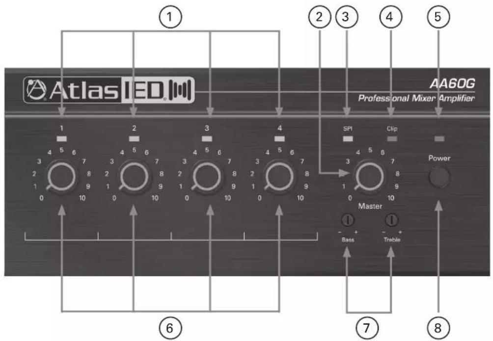
1. Input Signal Presence/Clip Indicators
Green LED, one above each channel's volume control, illuminates when input signal exceeds -40 dBu, and flashes brightly at threshold of audible distortion.
2. Master Level Control
The Master Level control will raise or lower all the input channels together. A good starting point for setting gain structure is to set the Master Level control at the 12:00 position, and then adjust the individual channels one at a time.
3. Output Signal Indicator
Green LED above master level control illuminates when any input signal exceeds -40 dBu.
4. Output Signal Clip Indicator
Red LED above master output volume control flashes brightly at threshold of audible distortion.
5. Power Indicator
This LED illuminates Blue when the power switch is turned On.
6. Input Level Controls
The rotary control varies the amplitude of the signal fed to the amplifier input. Turn clockwise to increase and counter-clockwise to decrease the signal level. Four controls in AA60G; three controls in AA35G.
7. Tone Controls
Bass and Treble nondetented recessed potentiometers under master level control. Bass ±10 dB at 100 Hz, Treble ±10 dB at 10 kHz.
8. Power Switch
This push switch (On/Off) supplies power to the mixer amplifier.
AA35G / AA60G
Owner's Manual
Rear Panel

1. AC Power Inlet
Detachable IEC accepts US or Euro style power cords.
2. Amplifier Outputs
For loudspeaker connections, connect as follows or proceed to the setup section for typical wiring schemes.
• COM - Loudspeaker common or negative connection
- 8Ω - Connect to positive terminal on direct coupled loudspeakers
- 70V - Connect to positive terminal on transformer coupled loudspeakers
- 100V - Connect to positive terminal on transformer coupled loudspeakers
3. Amp Configuration DIP Switch
Understanding the functionality of the DIP switches is key to maximizing the versatility of the AA35G/AA60G. When a switch is in the up position, the function is "ON" and when a switch is in the down position, the function is "OFF".
- On: Sets CH1 to Mic Input. Off: Sets CH1 to Line Input.
- On: Sets CH1 to Normal mode (no priority).
- On: CH1 priority contact closure mutes other channels.
- On: CH1 VOX mutes other channels by sensing signal through Input 1.
- On: Routes CH1 to Zone 2 output.
- On: Routes CH2 to Zone 2 output.
- On: Routes CH3 to Zone 2 output.
- On: 15V phantom power.
4. Input Connectors 2-3 (AA35G) or 2-4 (AA60G)
Unbalanced line-level RCA-type connectors, summed to mono.
AA35G / AA60G
Owner's Manual
5. Line Output Connector
3-Pin Balanced Euroblock connector. Line level output is Pre Master Level control. Use this output to connect signal to a secondary amplifier.
6. Zone 2 Level Control
Potentiometer adjusts level for both Zone 2 outputs.
7. Zone 2 Output Terminals
4-terminal Euroblock connector (2 terminals for 1W output to 8Ω loudspeaker, 2 terminals for 600Ω output to PBX MOH, music-on-hold, port or an additional amplifier).
8. VOX Threshold
Potentiometer controls how loud the voice on CH1 must be before muting other channels. Can be set for no muting. VOX is also known as Voice Activation Mute. This potentiometer controls the threshold of the mute bus. The mute threshold is determined by the adjustment of this control and the level at which the person is talking into the microphone. The higher the setting the less voice level it requires to trigger the mute bus.
9. Input 1 Connector
Five terminal Euroblock connector. Three terminals for balanced signal and two terminals for priority contact closure, which mutes other channels when DIP switch 3 is on. This input accepts balanced Mic, Line, and Telco line level outputs. Note: For Telco unbalanced signals the (-) negative pin and (G) ground pin need to be tied together. In some rare situations if a hum is present, a 600Ω isolation transformer may be required. This for older type Telco systems.
Installation
CAUTION: Ensure the mixer amplifier is disconnected from the power source, with power switch in the "Off" position and all level controls turned completely counterclockwise before beginning installation.
Use a standard 19" (483mm) equipment rack with an optional rack-mount kit. See below for dimensions.
You may also stack mixer amplifiers without using a cabinet or you may place a single mixer amplifier on a surface with 12" of air space around the unit for convection cooling.
NOTE: When transporting in a rack, mixer amplifiers should be supported at the front and back.
When using an equipment rack, do not mount units directly on top of each other. Allow 2 rack units (3.5") between units for convection cooling. The side walls of the rack should be a minimum of 2" (51mm) away from the mixer amplifier sides and the back of the rack should be a minimum of 4" (102mm) from the mixer amplifier back panel.
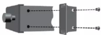
How to Attach the Unit to a Rack
- Remove the two screws from each side of the chassis near the front.
- Place a rack ear flush with the right front of the chassis.
- Insert a screw that you removed into the bottom hole of the rack ear and chassis. Screw it in.
- Insert a screw that you removed into the center hole of the rack ear and chassis. Screw it in.
- Insert one of the supplied screws into the top hole of the rack ear and chassis. Screw it in.
- Repeat steps 3 - 6 for the left side of the chassis.

natural_image
Mechanical assembly diagram showing two components with alignment lines (no text or symbols)Figure 2.2 How to Connect Rack Ears
AA35G / AA60G
Owner's Manual
Choose Input Wire and Connectors
AtlasIED recommends using balanced line (two-conductor plus shield), 22-24 gauge cables and connectors. Unbalanced line may also be used but may result in noise over long cable runs.
The AA35G and AA60G have two types of input connectors: Euroblock and RCA.
- Mic / Line Connector (CH1): 5-pin Euroblock, balanced, pins 3, 4 and 5 (Figure 2.3).
- Dual RCA Input Connector (other channels): For stereo music signals, unbalanced, summed together, two connectors per input (Figure 2.4).
To Mic or Line-Level Source
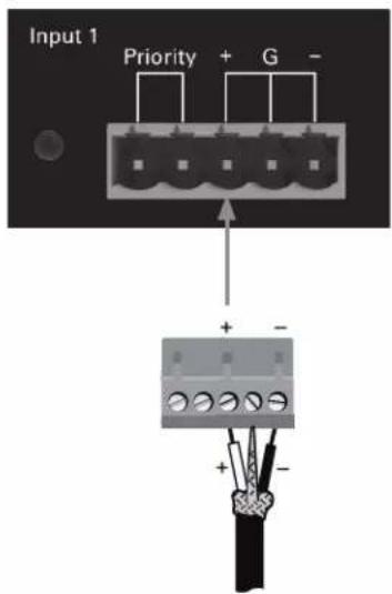
Figure 2.3 Mic / Line Connector

To Stereo Line-Level Source
Figure 2.4
Dual RCA Input Connector
AA35G / AA60G
Owner's Manual
Choose Output Wire and Connectors
Amplifier Output Connections: Slip the cable lugs under the output screw terminals and tighten (Figure 2.5). Slide the supplied non-touch cover over the output connections from top to bottom to cover them. AtlasIED recommends using high-quality, two-conductor, heavy gauge speaker wire and connectors. Crimp-on spade lugs may be used for the output connectors. To prevent the possibility of short-circuits, wrap or otherwise insulate exposed loudspeaker cable connectors. Cover the output connections with the supplied clear non-touch cover by sliding the cover on. Using the guidelines below, select the appropriate size of wire based on the distance from amplifier to loudspeaker. The wire sizes apply to the 8Ω tap.
Distance Wire Size
| up to 25 ft. | 16 AWG | ||
| 26-40 ft. | 14 AWG | ||
| 41ft. + | 12 | AWG |
NOTE: Custom wiring should only be performed by qualified personnel. Class 2 wiring is required.
CAUTION: Never use shielded cable for output power wiring.
Use 2-conductor shielded cable and a 3-pin Euroblock connector for Preamp Line Output (Figure 2.6).
Zone 2 Connections
If an external music source is connected to the AA35G or AA60G, its music can play over a phone line while the caller is on hold. Use the connection shown in Figure 2.7 (either 8 or 600 ) to connect the mixer amplifier to the Music-On-Hold input on the telephone system interface / PBX.

Figure 2.5 Amplifier Output Connections

Figure 2.6 Connections to the Preamp Output Connector

Figure 2.7 Connections to the Telephone (MOH or Amplifier Input) Connector

Atlas

1601 JACK MCKAY BLVD. ENNIS, TEXAS 75119 U.S.A.
TELEPHONE: (800) 876-3333 SUPPORT@ATLASIED.COM
AtlasIED.com
AA35G / AA60G
Owner's Manual
Wire the System
Typical input and output wiring is shown in Figure 2.8.
INPUTS: For Input 1, connect a microphone or balanced line-level signal to the Input 1 balanced input. Set the Mic / Line switch (DIP switch #1) accordingly. For the other inputs, connect unbalanced line-level signals to the RCA input connectors.
OUTPUTS: Maintain proper polarity (+/-) on amplifier output connectors. Connect the Amplifier Output screw terminals to the loudspeaker loads. Use terminals marked COM and 70V or 100V for constant voltage loudspeaker loads. Use terminals marked COM and 8Ω for an 8Ω loudspeaker. Connect the COM terminal to loudspeaker negative (-) lead; connect one of the other terminals to loudspeaker positive (+) lead. Cover the output connections with the supplied clear non-touch cover by sliding the cover on.
Phantom Power
Condenser microphones require phantom power to operate. If you are using a condenser microphone on Input 1, turn on DIP switch #8 on the back of the mixer-amp. The microphone must be able to work on 15V phantom power, which the mixer amplifier's mic input connector provides.
Figure 2.8
Input-Output Wiring

flowchart
graph TD
    A["Loudspeakers with 70V Transformers"] --> B["CD Player"]
    B --> C["Satellite Receiver"]
    C --> D["In-Ceiling Loudspeaker"]
    D --> E["Telephone System Interface / PBX"]
    E --> F["5-Terminal Removable Barrier Block (Euroblock)"]
    F --> G["To Mic"]
    G --> H["Paging Mic"]
    H --> I["Switch Mutes Other Channels"]
    I --> J["To Switch In Mic."]
    J --> K["VOXThreshold"]
    K --> L["High Sensitivity"]
    L --> M["Low Output"]
    M --> N["Line Output (Pre Master Level)"]
    N --> O["AMP Config"]
    O --> P["1 - CH1 Mic OnLine Off 5 - CH1 to Zone 2"]
    O --> Q["2 - CH1 Normal 6 - CH2 to Zone 2"]
    O --> R["3 - CH1 Priority 7 - CH3 to Zone 2"]
    O --> S["4 - CH1 VOX 8 - Phantom"]
    O --> T["Input 4 - Unbalanced Sum"]
    T --> U["Input 3 - Unbalanced Sum"]
    U --> V["Atlas IED"]
    V --> W["Input 2 - Unbalanced Sum"]
AA35G / AA60G
Owner's Manual
Operation
Powering Up
- Turn Off any equipment connected to the Preamp Output connector.
- Plug the amplifier's power cord into a 3-wire grounded AC outlet.
- Turn down the input volume controls.
- Turn down the master volume control.
- Turn on the Power switch. The Power indicator should glow.
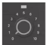
- Turn the input volume controls in use about 34 up.
- Turn up the master volume control(s) until the desired loudness or power level is achieved.
- Touch up the input levels as needed for music and voice.
- Turn on any equipment connected to the Preamp Output connector.
Disconnect the power cord before making any wiring or installation changes.
Priority Muting
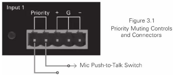
Follow this procedure to allow the microphone's push-to-talk switch to mute the background music or other input signals.
On the back of the AA35G or AA60G:
- Turn DIP switch 2 "Off" Turn DIP switch 3 "On".
- Connect a push-to-talk mic contact to the Priority Connector (Figure 3.1). Input 1 is the priority input for the amplified output, so Input 1 mutes the other inputs.
Voice-Activated (VOX) Muting
Follow this procedure to allow a voice to mute the background music or other input signals.
On the back of the AA35G or AA60G:
- Turn DIP switch 4 "On" Turn DIP switches 2 and 3 "Off".
- Talk into the microphone. Adjust the VOX threshold potentiometer on the back of the unit to set how loud the voice must be before muting occurs. It can be set for no muting.
Zone 2 Output
On the back of the unit, adjust Zone 2 Level Control to obtain the desired noise level.
AA35G / AA60G
Owner's Manual
Troubleshooting
CONDITION: No power to the mixer amplifier.
POSSIBLE REASON:
- The mixer amplifier's power switch is Off.
- The mixer amplifier is not plugged into the AC power receptacle.
- The mixer amplifier's high-voltage power supply circuit breaker has tripped. Verify that the AC mains voltage is correct.
CONDITION: Distorted sound.
POSSIBLE REASON:
- Input signal level is too high. Turn down the input level controls.
Note: The mixer-amplifier should never be operated at a level which causes the Clip LEDs to illuminate constantly. - Master volume level is too high. Turn it down to about 34 of maximum level.
CONDITION: No sound.
POSSIBLE REASON:
- The amplifier is in "fault" mode. A Fault status can be triggered when one of the amplifier's protection circuits is activated. First disconnect your loudspeakers from the affected channel(s) one by one to determine if one of the loads is shorted. If an amplifier channel has a thermal fault, there will be no indication on the front panel, but the amp will recover after cooling. If operation does not return to normal after restarting the amplifier, contact AtlasIED at 1-800-876-3333.
POSSIBLE REASON:
- No input signal.
- Input signal level is very low.


AA35G / AA60G
Owner's Manual
| System AA35G AA60G | ||
| Type 35-Watt Mixer Amplifier 60-Watt Mixer Amplifier | ||
| Power Supply Type Global Switch Mode Global Switch Mode | ||
| Amp Topology Class AB Class AB | ||
| Number of Fixed Inputs 3 4 | ||
| Accessory Inputs N/A N/A | ||
| DSP Internal | N/A N/A | |
| Network | N/A N/A | |
| Optional Accessory Card Slot | N/A N/A | |
| Output Power (Note 1) | ||
| 100V | 35-Watts 60-Watts | |
| 70V | 35-Watts 60-Watts | |
| 8Ω | 35-Watts 60-Watts | |
| Front Panel | ||
| Power Switch | Push Type | Push Type |
| Indicators Output | Signal, Clip, Power | Signal, Clip, Power |
| Indicators Input | Signal | Signal |
| Output Limiter | N/A N/A | |
| PHD Test Circuit | N/A N/A | |
| Level Controls | Master, Inputs 1-3 | Master, Inputs 1-4 |
| EQ Output Bass | Yes | Yes |
| EQ Output Treble Yes | Yes | |
| Mic / Line / AUX Inputs | ||
| Input Quantity | 3 4 | |
| Mic / Line / Telco(Balanced, 3 Position PHX Type, 3.5mm Pitch) | 1 | 1 |
| Aux RCA (Unbalanced RCA L & R Sum) | 2 3 | |
| Aux 3.5mm (Unbalanced 3.5mm L & R Sum) | N/A N/A | |
| Speciality Inputs | ||
| Line Input Balanced(Balanced, 3 Position PHX Type, 3.5mm Pitch) | N/A N/A | |
| Line Input Unbalanced (RCA) | N/A N/A | |
| Room Combine - Bridge Buss In / Out (Line LevelBalanced 5 Position PHX Type, 3.5mm Pitch) | N/A N/A | |
| Amp In(Balanced, 3 Position PHX Type, 3.5mm Pitch) | N/A N/A | |
| Input Mute | ||
| VOX (Input 1 Activated)(Assignable Inputs, VOX Threshold Sensitivity) | Fixed Assignment | Fixed Assignment |
| Priority / Remote Mute: Assignable Inputs,Contact Closure (2 Position PHX) | Fixed Assignment | Fixed Assignment |
| Remote Level | ||
| Type (External Variable Resistance 10kΩ - 0Ω) | N/A | N/A |
| Connector (2 Position PHX Type, 3.5mm Pitch) | N/A N/A | |
| Assignment(Input 6 or Master, Dip Switch Selection) | N/A N/A | |
AA35G / AA60G
Owner's Manual
| Outputs | ||
| Main (Class 2 Wire Rated)Transformer Coupled Taps | 8Ω, 70.7V, 100V 8Ω, 70.7V, 100V | |
| Main Output Termination(Barrier Strip Screw Terminal) | Yes Yes | |
| Zone 2 1W 8Ω with Level Control(2 Position PHX Type, 5.08mm Pitch) | Yes Yes | |
| Zone 2 Balanced / MOH with Level Control(600Ω, Max 1.0V Out, 2 Position PHX Type,5.08mm Pitch) | Yes Yes | |
| Pre Out(Balanced, 2V Max, Pre Master Level Control) | Yes Yes | |
| Control Switch Functions | ||
| Zone 2 (Assignable) Yes Yes | ||
| Mute Receive (Assignable) Yes Yes | ||
| Phantom Power (24V) Yes Yes | ||
| Mic/Line Select (Inputs 1, 2, 3, 4) Input 1 Input 1 | ||
| Remote Level Assignment(Input 6 or Master Level) | N/A N/A | |
| Lo Cut Filter(400Hz Hi-Pass Filter, By-passes Bass EQ) | N/A N/A | |
| Technical Data | ||
| Frequency Response (LF +/- 3db, HF +/- 1dB) Yes Yes | ||
| THD+N (0.5% or Less, at 1kHz, Rated Output) Yes Yes | ||
| Input Impedance (Mic / Line / TelcoBalanced 1200Ω, Unbalanced 10kΩ) | ||
| Mic Mode | 3mV | 3mV |
| LineMode | 800mV | 800mV |
| 3.5mm L & R Unbalanced Summed | NA | NA |
| RCA Unbalanced L & R Summed | 400mV | 400mV |
| Signal To Noise Ratio | ||
| Mic | 55dB | 55dB |
| Balanced Line | 55dB | 55dB |
| 3.5mm L & R Unbalanced Summed | 75dB | 75dB |
| RCA Unbalanced L & R Summed | 75dB | 75dB |
| Phantom Power (Mic Mode) | 24V | 24V |
| EQ | ||
| Output Bass | ±6dB @ 100Hz | ±6dB @ 100Hz |
| Output Treble | ±6dB @ 10kHz | ±6dB @ 10kHz |
| DSP | NA | NA |
| Power Requirements | ||
| AC Mains Operating Range (100V - 240v 50 / 60 Hz) | Yes Yes | |
| AC Cord (IEC to NEMA 5-20P, 2M, 18-Gauge) | Yes | Yes |
| Idle Power (Amps, Watts, BTU) | 0.18A, 11W, 37 BTU | 0.27A, 16W, 54 BTU |
| Average Power - Note 3 (Amps, Watts, BTU) | 0.75A, 54W, 184 BTU | 1.09A, 81W, 276 BTU |
| Max Power - Note 1 (Amps, Watts, BTU) | 1.15A, 90W, 307 BTU | 1.67A, 131W, 446 BTU |
AA35G / AA60G
Owner's Manual
| Cooling | ||
| APD Standby, Active Idle Convection Cooled Convection Cooled | ||
| In Use Convection Cooled Convection Cooled | ||
| Cooling Air Flow Direction N/A N/A | ||
| Mechanical | ||
| Chassis Steel Steel | ||
| Finish Black Paint Black Paint | ||
| Agency Approvals | ||
| RoHS Compliant Yes Yes | ||
| Safety Listings Yes Yes | ||
| CB | Yes Yes | |
| FCC | N/A N/A | |
| Dimensions and Weight | ||
| Rack Mount Requirements | AAGRMK2 Rack Mount Kit (2RU) AAGRMK2 Rack Mount Kit (2RU) | |
| Dimensions - Unit | 8.25" W x 3.5" H x 12.25" D (210mm x 90mm x 311mm) | 8.25" W x 3.5" H x 12.25" D (210mm x 90mm x 311mm) |
| Dimensions - Shipping | 15.3" W x 6.8" H x 10.8" D (389mm x 173mm x 275mm) | 15.3" W x 6.8" H x 10.8" D (389mm x 173mm x 275mm) |
| Weight - Unit | 8.2 lbs (3.7 kg) | 9.7 lbs (4.3 kg) |
| Weight - Shipping | 10.55 lbs (4.78 kg) | 12.11 lbs (5.49 kg) |
NOTES:
- Power level measurement is defined as follows: 1Hz Sine wave signal 1 second at 1% THD+N
- If the amplifier specifies 8 ohm load, a 4 ohm load can be applied but will deliver the power rating of 8 ohm. If driven past this power rating the amplifier will go into protect.
- Average Power is defined as Pink Noise input signal applied to achieve 1/3 of the 4 Ohm or 70.7V power rating.
- Max Power is defined as 1 KHz input signal applied to achieve the maximum power output before clipping into a 4 Ohm or 70.7V load.
- BTU is calculated by the AC Mains Power consumed minus the total power output measured at the specified load and condition, multiplied by 3.412. Example: 785 Watts from the AC Source - 600 Watts Total Output power = 185 x 3.412 = 631 BTU
AA35G / AA60G
Owner's Manual
Notes:
AA35G / AA60G
Owner's Manual
Notes:
AA35G / AA60G
Owner's Manual
Notes:
Limited Warranty
All products manufactured by AtlasIED are warranted to the original dealer/installer, industrial or commercial purchaser to be free from defects in material and workmanship and to be in compliance with our published specifications, if any. This warranty shall extend from the date of purchase for a period of three years on all AtlasIED products, including SOUNDOLIER brand, and ATLAS SOUND brand products except as follows: one year on electronics and control systems; one year on replacement parts; and one year on Musician Series stands and related accessories. Additionally, fuses and lamps carry no warranty. AtlasIED will solely at its discretion, replace at no charge or repair free of charge defective parts or products when the product has been applied and used in accordance with our published operation and installation instructions. We will not be responsible for defects caused by improper storage, misuse (including failure to provide reasonable and necessary maintenance), accident, abnormal atmospheres, water immersion, lightning discharge, or malfunctions when products have been modified or operated in excess of rated power, altered, serviced or installed in other than a workman like manner. The original sales invoice should be retained as evidence of purchase under the terms of this warranty. All warranty returns must comply with our returns policy set forth below. When products returned to AtlasIED do not qualify for repair or replacement under our warranty, repairs may be performed at prevailing costs for material and labor unless there is included with the returned product(s) a written request for an estimate of repair costs before any nonwarranty work is performed. In the event of replacement or upon completion of repairs, return shipment will be made with the transportation charges collect.
EXCEPT TO THE EXTENT THAT APPLICABLE LAW PREVENTS THE LIMITATION OF CONSEQUENTIAL DAMAGES FOR PERSONAL INJURY, ATLASIED SHALL NOT BE LIABLE IN TORT OR CONTRACT FOR ANY DIRECT, CONSEQUENTIAL OR INCIDENTAL LOSS OR DAMAGE ARISING OUT OF THE INSTALLATION, USE OR INABILITY TO USE THE PRODUCTS. THE ABOVE WARRANTY IS IN LIEU OF ALL OTHER WARRANTIES INCLUDING BUT NOT LIMITED TO WARRANTIES OF MERCHANTABILITY AND FITNESS FOR A PARTICULAR PURPOSE.
AtlasIED does not assume, or does it authorize any other person to assume or extend on its behalf, any other warranty, obligation, or liability. This warranty gives you specific legal rights and you may have other rights which vary from state to state.
Service
Should your amplifier require service, please contact the AtlasIED warranty department at 1-800-876-3333 or atlaswarranty@atlasied.com to obtain an RA number.
AtlasIED Tech Support can be reached at 1-800-876-3333 or www.atlasied.com/support
Visit our website at www.AtlasIED.com to see other AtlasIED products.
©2019 Atlas Sound L.P. The Atlas "Circle A", Soundolier, and Atlas Sound are trademarks of Atlas Sound L.P. IED is a registered trademark of Innovative Electronic Designs LLC. All Rights Reserved. All other trademarks are the property of their respective owners. All specs are subject to change without notice. ATS005530 RevG 8/19

- AA35G & AA60G Commercial Mixer Amplifier
- AA35G / AA60G
- Owner's Manual
- Important Safety Instructions
- WARNING
- NING - When The Device Is In Use
- TION - When Installing The Product
- TION - When The Product Is In Use
- Introduction
- Key Features
- Applications
- Input Signal Presence/Clip Indicators
- Master Level Control
- Output Signal Indicator
- Output Signal Clip Indicator
- Power Indicator
- Input Level Controls
- Tone Controls
- Power Switch
- AC Power Inlet
- Amplifier Outputs
- Amp Configuration DIP Switch
- Input Connectors 2-3 (AA35G) or 2-4 (AA60G)
- Line Output Connector
- Zone 2 Level Control
- Zone 2 Output Terminals
- VOX Threshold
- Input 1 Connector
- Installation
- How to Attach the Unit to a Rack
- Choose Input Wire and Connectors
- Choose Output Wire and Connectors
- Zone 2 Connections
- Wire the System
- Phantom Power
- Operation
- Powering Up
- Priority Muting
- Voice-Activated (VOX) Muting
- Zone 2 Output
- Troubleshooting
- CONDITION: No power to the mixer amplifier.
- CONDITION: Distorted sound.
- CONDITION: No sound.
- NOTES:
- Limited Warranty
- Service
Brand : ATLAS
Model : AA35G
Category : Receiver