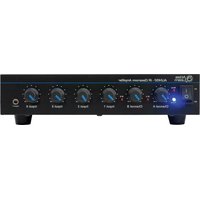
AL2450 - Receiver ATLAS - Free user manual and instructions
Find the device manual for free AL2450 ATLAS in PDF.


| Product Type | Satellite Receiver / Digital Set-Top Box |
| Brand | ATLAS |
| Model | AL2450 |
| Dimensions (W x D x H) | Approx. 430 x 250 x 60 mm |
| Weight | Approx. 2.5 kg |
| Power Supply | AC 100-240V, 50/60Hz or DC 12V (check adapter) |
| Power Consumption | < 30 W (max) |
| Tuner Type | DVB-S/S2, MPEG-4 |
| Input Connectors | F-type (satellite), RCA (audio/video), HDMI |
| Output Connectors | HDMI, SCART (optional), Optical audio, RCA |
| Main Functions | Electronic Program Guide (EPG), channel list, parental lock, software update via USB, fast channel switching |
| Video Resolution | Up to 1080p |
| Audio Decoding | MPEG-1 Layer I/II, MPEG-2, Dolby Digital (optional) |
| Maintenance & Cleaning | Use a dry soft cloth; do not use liquid cleaners. Keep ventilation slots clear. |
| Safety Instructions | Place on a flat, stable surface; avoid moisture; unplug during storms; do not open the casing. |
| Spare Parts & Repairability | Contact authorized service centers; spare parts available through certified distributors for at least 5 years after discontinuation. |
| General Information | Operating temperature: 0-40°C; humidity: 20-80%; for indoor use only. |
Frequently Asked Questions - AL2450 ATLAS
User questions about AL2450 ATLAS
0 question about this device. Answer the ones you know or ask your own.
Ask a new question about this device
Download the instructions for your Receiver in PDF format for free! Find your manual AL2450 - ATLAS and take your electronic device back in hand. On this page are published all the documents necessary for the use of your device. AL2450 by ATLAS.
USER MANUAL AL2450 ATLAS
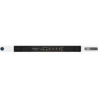
AL2450 Amplifier/Receiver


Atlas
IED.
1601 Jack McKay Blvd. • Ennis, Texas 75119 U.S.A.
Telephone:800.876.3333•Fax:800.765.3435
- 1 - AtlasIED.com
Table of Contents
Important Safety Instructions....3
Introduction 5
Key Features .... 5
Applications 5
Front Panel Description....6
Rear Panel Description....7
Installation....8
Wiring 8
AL2450 Block Diagram....9
Specifications 10
Warranty 12
Important Safety Instructions


WARNING: SHOCK HAZARD - DO NOT OPEN AVIS: RISQUE DE CHOC ELÉCTRIQUE - NE PAS OUVRIR
WARNING: TO REDUCE THE RISK OF FIRE OR ELECTRIC SHOCK DO NOT EXPOSE THIS EQUIPMENT TO RAIN OR MOISTURE
AVIS: NE PAS EXPOSER CE MATÉRIEL À LA PLUIE OU L'HUMIDITE AFIN DE REDUIRE LE RISQUE D'INFLAMMATION OU DE CHOC ÉLÉCTRIQUE

The lightning flash with arrowhead symbol within an equilateral triangle, is intended to alert the user to the presence of uninsulated "dangerous voltage" within the product's enclosure that may be of sufficient magnitude to constitute a risk of electric shock to persons.

The exclamation point within an equilateral triangle is intended to alert the user to the presence of important operating and maintenance (servicing) instructions in the literature accompanying the product.
- Read these instructions.
- Keep these instructions.
- Heed all warnings.
- Follow all instructions.
- Do not use this device near water.
- Clean only with dry cloth.
- Do not block any ventilation openings. Install in accordance with the manufacturer's instructions.
- Do not install near any heat sources such as radiators, heat registers, stoves, or other device that produce heat.
- Do not defeat the safety purpose of the polarized or grounding-type plug. A polarized plug has two blades with one wider than the other. A grounding type plug has two blades and a third grounding prong. The wide blade or the third prong are provided for your safety. If the provided plug does not fit into your outlet, consult an electrician for replacement of the obsolete outlet.
- Protect the power cord from being walked on or pinched particularly at plugs, convenience receptacles, and the point where they exit from the device.
- Only use attachments/accessories specified by the manufacturer.
- Use only with the cart, stand, tripod, bracket, or table specified by the manufacturer, or sold with the device. When a cart is used, use caution when moving the cart / device combination to avoid injury from tip-over.

- Unplug this device during lightning storms or when unused for long periods of time.
- Refer all servicing to qualified service personnel. Servicing is required when the device has been damaged in any way, such as power-supply cord or plug is damaged, liquid has been spilled, or objects have fallen into the device, the device has been exposed to rain or moisture, does not operate normally, or has been dropped.
- This product is equipped with a three-wire grounding-type plug, a plug having a third (grounding) pin. This plug will only fit into a grounding-type power outlet. This is a safety feature. If you are unable to insert the plug into the outlet, contact your electrician to replace your obsolete outlet. Do not defeat the safety purpose of the grounding-type plug.
- WARNING: To reduce the risk of fire or electric shock, this device should not be exposed to rain or moisture and objects filled with liquids, such as a vase, should not be placed on this device.
- To completely disconnect this equipment from the mains, disconnect the power supply cord plug from the receptacle.
- The mains plug of the power supply cord shall remain readily operable.
- ⏚ Protective earthing terminal. The apparatus should be connected to a mains socket with a protective earthing connection.

NING - When The Device Is In Use
- WARNING: For the terminals marked with symbol of heckmark may be of sufficient magnitude to constitute a risk of electric shock. The external wiring connected to the terminals requires installation by an instructed person or the used of ready-made leads or cords.
- WARNING: The apparatus shall not be exposed to dripping or splashing and that objects filled with liquids, such as vases, shall not be placed on apparatus.
- WARNING: The mains plug is used as disconnect device, the disconnect device shall remain readily operable.
- To prevent electric shock, do not remove the product cover as there are high voltage components inside. Refer all servicing to AtlasLED.
- Should any of the following irregularities occur during use, immediately switch off the power, disconnect the power cord from the AC outlet and contact AtlasLED. Do not to attempt to continue operation with the product as this may cause fire or electric shock:
- Smoke or strange smell coming from the unit.
• If the product falls or the case is damaged. - If water or any metallic objects falls into the product.
• If the power supply cord is damaged in any way. - If the unit is malfunctioning.
- Do not insert or drop metallic objects or flammable materials into the ventilation holes of the product's cover, as this may result in electric shock or fire.
- Do not place any containers with liquid or metallic objects on the top of the product. If any liquid spills into the unit, fire or electric shock may result.
- Never operate this product or touch the power supply cord during an electrical storm, electric shock may result.
- Never exceed the power rating on the product when connecting equipment. Fire and/or property damage may result.
- Operate the product only with the voltage specified on the unit. Fire and/or electric shock may result if a higher voltage is used.
- Do not modify, kink, or cut the power cord. Do not place the power cord in close proximity to heaters and do not place heavy objects on the power cord, including the product itself, doing so may result in fire or electrical shock.
- Ensure that the safety ground terminal is connected to a proper ground. Never connect the ground to a gas pipe as a catastrophic disaster may result.
- Be sure the installation of the product is stable, avoid slanted surfaces as the product may fall and cause injury or property damage.

UTION - When Installing The Product
- Plugging in or unplugging the power cord with wet hands may result in electric shock.
- Never move the unit with the power cord plugged into the wall, as damage to the power cord may result.
- When unplugging the cord from the wall, grasp the plug, NOT the cord.
- Never install this product in humid or dusty locations, nor in direct sunlight, near sources of heat, or in areas where sooty smoke or steam are present. Fire and electric shock may result.
- Keep all sides of the unit at least 3 1/2 away from objects that may obstruct air flow to prevent the unit's internal temperature rise.

UTION - When The Product Is In Use
- Never place heavy objects on the product, causing it to fall and/or break, resulting in personal injury and property damage. In addition, the product itself may fall and cause injury and property damage.
- Contact AtlasIED for instructions on cleaning the inside of the unit. Large accumulations of dust inside the unit may result in heat buildup and fire.
- Ensure that the power supply plug is securely plugged into the wall outlet. Never allow dust to accumulate on the power plug or inside the wall outlet.
- When cleaning the unit or the unit is not to be operated for an extended period, unplug the power cord from the wall.
Introduction
Congratulations and thank you for purchasing the AtlasIED AL2450 Atlas Learn wireless infrared sound reinforcement receiver / amplifier. This new and innovative professional grade audio system has been designed from the ground up to include unique features required for delivering clear and concise audio to the classroom.
Key Features
• Works in Conjunction with Secondary Systems to Provide Enhanced Classroom Security
- Provides Excellent Infrared Wireless Sound Reinforcement
- Easily Integrates Into Any Classroom
• 50 Watts Output at 8Ω, 25V, and 70.7V
• 6 Input Mixer with Priority Page Override
• Patent Pending Pole Mount Design
Applications
The Atlas Learn AL2450 receiver / amplifier is an in-classroom sound reinforcement solution designed for use in K-12 and higher education facilities or where a room constrained public address system is required. This amplifier / receiver is designed to work with Atlas Learn wireless infrared microphones, AL-MAGPIE and AL-MYNA, to allow teachers and students to walk freely around the room with the infrared microphones / system control units and project their voices through installed speakers.
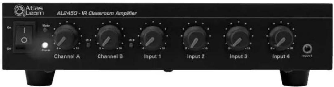
Front Panel

1. Power Switch
This toggle switch applies power to the AL2450.
2. Power LED
This LED will illuminate when the AL2450 is turned on.
3. Mute LED
This LED will illuminate when the AL2450 source inputs are muted using MODE 2 of the AL-PH microphone.
4. IR A LED
This LED will illuminate when an active AL-MAGPIE or AL-MYNA microphone is set to Channel A.
5. IR B LED
This LED will illuminate when an active AL-MAGPIE or AL-MYNA microphone is set to Channel B.
6. Channel A
The gain for Mic Channel A is controlled by this rotary control.
7. Channel B
The gain for Mic Channel B is controlled by this rotary control.
8. Inputs 1 - 4
The gain for Inputs 1 - 4 are controlled by these rotary controls.
9. Input 4
This 3.5mm input jack provides unbalance stereo summing inputs from iPods™ / MP3 players and overrides the input of the rear panel Input 4.
Rear Panel
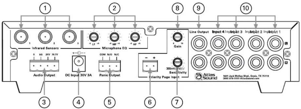
1. Infrared Sensors
These three "F" type connectors are for input of the AL-IRDS antennas.
2. Microphone EQ
These three rotary controls provide equalization of the wireless microphones. This 3 band EQ is centered at 100Hz, 3kHz, and 10KHz.
3.AudioOutput
For loudspeaker connections, connect using the following information or proceed to the setup section for typical wiring diagrams.
COM - Speaker common or negative connection
8Ω - Connect to direct coupled loudspeakers
25V - Connect to transformer coupled, 25V loudspeakers with a total load impedance of no less than 20.8Ω.
70V - Connect to transformer coupled, 70.7V loudspeakers with a total load impedance of no less than 167Ω.
4. DC Input 30V
AL2450 power supply input. Note: Use only supplied power supply.
5. Panic Output
This SPDT relay output is controlled via the PANIC button on the wireless microphones.
6. Priority Page Input
This input accepts line or speaker level input to allow an external source to override the audio output of the AL2450.
7. Priority Page Sensitivity
This rotary control is used to set the input sensitivity of the Priority Page Input.
8. Priority Page Gain
Sets audio gain for the Priority Page Input.
9. Line Output
This unbalanced output can be used to feed the AL2450 mix bus to additional amplifiers or recording devises.
10. Inputs 1 - 4
These dual RCA summing inputs are used for the input of auxiliary audio sources like FM tuners, CD / DVD, TV / VCR, and computer sound cards. Note: Input 4 can be overridden by the front panel 3.5mm input.
AL2450 Installation Description
- Unpack AL2450 and confirm that the unit is undamaged.
- Find suitable location for the AL2450 receiver / amplifier within 10' of a 120VAC outlet.
- Route supplied RG-6 coaxial cable from AL-IRDS (sold separately) to AL2450. An appropriate location is high on a wall, on the ceiling, or somewhere it will have a line of site view from the AL-MAGPIE / AL-MYNA (sold separately) transmitters.
- Install appropriate 70.7V speakers and route a 2 conductor unshielded cable from the AL2450 to the speakers. Set the appropriate tap for the speakers being conscious of the 50 Watts maximum output of the AL2450 amplifier.
- Connect the audio output of all the associated multimedia sources to the appropriate input on the rear of the AL2450 receiver / amplifier.
- Once all the external wiring is complete and the batteries in the chosen wireless transmitters are changed, turn on the AL2450 receiver / amplifier and set all front panel volume controls to the "9 o'clock" position.
- Set one wireless microphone to IR Channel A and the other wireless microphone to Channel B. Power on both wireless microphones by holding each power button for three seconds and confirm that the appropriate IR Channel LEDs on the AL2450 are illuminated.
- Speak into the microphone and press the Up Volume button on the wireless microphone until the desired volume is reached at the speakers. If the appropriate level cannot be attained, increase the front panel Channel A or B volume on the AL2450 until maximum volume without feedback is reached and then adjust the microphone volume on the wireless microphone for proper listening level.
- Walk around the room while speaking into the microphone to confirm there are no signal dropout locations. If a signal dropout location is found, relocate one of the AL-IRDS antennas.
Wiring the AL2450
Speaker Outputs
Use 2 conductor unshielded, twisted pair stranded wire of the appropriate gauge. If you are unsure about this, contact AtlasLED Tech Support at 1-800-876-3333. Make sure you know how many speakers you need and what tap value you intend to use.
IR Domes
Use RG-6 coaxial cable. Both ends of the cable need to be terminated with "F" type connectors.
Unbalanced Inputs and Outputs
Pre-made RCA cables can be purchased from vendors to simplify interconnection to external devices
Priority Page Input
Use 2 conductor unshielded wire of the appropriate gauge. If you are unsure about this, contact AtlasIED Tech Support at 1-800-876-3333.
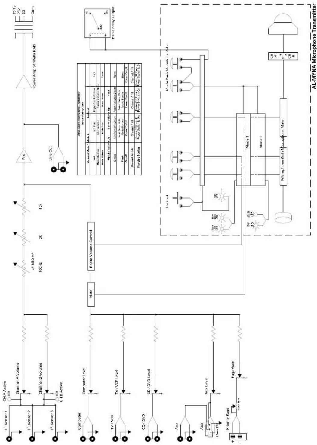
Block Diagram
flowchart
graph TD
    A["IR Sensor 1"] --> B["CH A Active"]
    C["IR Sensor 2"] --> D["Channel A Volume"]
    E["IR Sensor 3"] --> F["Channel B Volume"]
    G["Computer"] --> H["Computer Level"]
    I["TV / VCR"] --> J["TV / VCR Level"]
    K["CD / DVD"] --> L["CD / DVD Level"]
    M["Aux"] --> N["Aux Level"]
    O["Aux"] --> P["Aux Level"]
    Q["Priority Page"] --> R["Page Gain"]
    S["Line Out"] --> T["Line Out"]
    U["Power Amp 50 Watts RMS"] --> V["70.7V"]
    V --> W["25V"]
    V --> X["80"]
    V --> Y["Com"]

    Z["Alies Learn Microphone Transmitter Functionality Chart"] --> AA["Lockout"]
    AA --> AB["Mode 1"]
    AA --> AC["Mode 2"]
    AB --> AD["Left Blue"]
    AB --> AE["Right And Left Blue"]
    AC --> AF["Red"]
    AD --> AG["Mix Volume"]
    AE --> AH["Room Volume Down"]
    AF --> AI["Mide Button"]
    AG --> AJ["Mute Pin"]
    AH --> AK["Mute Room"]
    AI --> AL["Mute Switch"]
    AJ --> AM["Up Mic Volume Up"]
    AK --> AN["Down Mic Volume Down"]
    AL --> AO["Up Mic Volume Up"]
    AM --> AP["Mix Volume Down"]
    AN --> AQ["Mide Button"]
    AO --> AR["Mide Switch"]
    AP --> AS["Pain"]
    AQ --> AT["Pain Switch"]
    AR --> AU["Pain Switch"]

    AC --> AV["Up Mic Volume Up"]
    AV --> AW["Mix Volume Down"]
    AW --> AX["Up Mic Volume Up"]
    AX --> AY["None"]

    AZ["Alies Learn Microphone Transmitter Functionality Chart"] --> BA["Element Mode 1"]
    BA --> BB["Mode 2"]
    BB --> BC["Led"]
    BC --> BD["Left Blue"]
    BC --> BE["Right And Left Blue"]
    BE --> BF["Room Volume None"]

    BG["Alies Learn Microphone Transmitter Functionality Chart"] --> BH["Mode 1"]
    BH --> BI["Mode 2"]
    BI --> BJ["Led"]
    BJ --> BK["Left Blue"]
    BJ --> BL["Right And Left Blue"]
    BL --> BM["Room Volume None"]

    BN["Panic Relay Output"] --> BO["NC"]
    BO --> BP["CCM"]
    BO --> BQ["No"]

    BR["Alex Lockout"] --> BS["Mode 1"]
    BS --> BT["Blue Left LED"]
    BS --> BU["Blue Right LED"]

    BV["Mode 2"] --> BW["Mode 1"]
    BW --> BX["Blue Left LED"]
    BW --> BY["Blue Right LED"]

    CA["Alies Learn Microphone Transmitter Functionality Chart"] --> CB["Mode 1"]
    CB --> CC["Mode 2"]

Atlas
IED.
1601 Jack McKay Blvd. • Ennis, Texas 75119 U.S.A.
Telephone:800.876.3333•Fax:800.765.3435
System
| Type Receiver / Amplifier | |
| Multimedia Input Sensitivity -10dB | |
| Priority Page Input Sensitivity 14dB | |
| Computer Input Impedance 56K | |
| Multimedia Input Impedance 22K | |
| Multimedia Input Connector Type Dual RCA | |
| AUX Front Input Connector Type 3.5mm | |
| Line Output Impedance 1K | |
| Line Output Voltage 1.3V | |
| Line Output Connector Type Dual RCA | |
| Mic EQ (100Hz, 3kHz, & 10kHz) Adjustment | ±10dB |
| IR Input Impedance / Connector Type | 75Ω F Connector |
| Panic Output Contact Rating | 5A@ 36V |
| Speaker Output | 50W RMS @ 8Ω, 25V or 70.7V |
| In Line PSU Type | 100V-240V In, 24VDC / 2.5A Out |
| Dimensions and Weight | |
| Dimensions | 8 12 " W x 1 2 / 3 " H x 13 1/2 " D (216mm x 45mm x 343mm) |
| Weight | 5.75lbs (2.6kg) |
Notes:

Atlas

1601 Jack McKay Blvd. • Ennis, Texas 75119 U.S.A.
Telephone: 800.876.3333 • Fax: 800.765.3435
Limited Warranty
All products manufactured by AtlasLED are warranted to the original dealer/installer, industrial or commercial purchaser to be free from defects in material and workmanship and to be in compliance with our published specifications, if any. This warranty shall extend from the date of purchase for a period of three years on all AtlasLED products, including SOUNDOLIER brand, and ATLAS SOUND brand products except as follows: one year on electronics and control systems; one year on replacement parts; and one year on Musician Series stands and related accessories. Additionally, fuses and lamps carry no warranty. AtlasLED will solely at its discretion, replace at no charge or repair free of charge defective parts or products when the product has been applied and used in accordance with our published operation and installation instructions. We will not be responsible for defects caused by improper storage, misuse (including failure to provide reasonable and necessary maintenance), accident, abnormal atmospheres, water immersion, lightning discharge, or malfunctions when products have been modified or operated in excess of rated power, altered, serviced or installed in other than a workman like manner. The original sales invoice should be retained as evidence of purchase under the terms of this warranty. All warranty returns must comply with our returns policy set forth below. When products returned to AtlasLED do not qualify for repair or replacement under our warranty, repairs may be performed at prevailing costs for material and labor unless there is included with the returned product(s) a written request for an estimate of repair costs before any nonwarranty work is performed. In the event of replacement or upon completion of repairs, return shipment will be made with the transportation charges collect.
EXCEPT TO THE EXTENT THAT APPLICABLE LAW PREVENTS THE LIMITATION OF CONSEQUENTIAL DAMAGES FOR PERSONAL INJURY, ATLASIED SHALL NOT BE LIABLE IN TORT OR CONTRACT FOR ANY DIRECT, CONSEQUENTIAL OR INCIDENTAL LOSS OR DAMAGE ARISING OUT OF THE INSTALLATION, USE OR INABILITY TO USE THE PRODUCTS. THE ABOVE WARRANTY IS IN LIEU OF ALL OTHER WARRANTIES INCLUDING BUT NOT LIMITED TO WARRANTIES OF MERCHANTABILITY AND FITNESS FOR A PARTICULAR PURPOSE.
AtlasIED does not assume, or does it authorize any other person to assume or extend on its behalf, any other warranty, obligation, or liability. This warranty gives you specific legal rights and you may have other rights which vary from state to state.
Service
Should your AL2450 require service, please contact the AtlasIED warranty department at 1-877-689-8055, ext. 277 or www.atlasied.com/support to obtain an RA number.
AtlasIED Tech Support can be reached at 1-800-876-3333 or www.atlasied.com/support
Visit our website at www.AtlasLED.com to see other AtlasLED products.
©2018 Atlas Sound L.P. The Atlas "Circle A", Soundolier, and Atlas Sound are trademarks of Atlas Sound L.P. IED is a registered trademark of Innovative Electronic Designs LLC. All Rights Reserved. All other trademarks are the property of their respective owners. All specs are subject to change without notice. ATS005662 RevB 1/18

- Table of Contents
- Important Safety Instructions
- NING - When The Device Is In Use
- UTION - When Installing The Product
- UTION - When The Product Is In Use
- Introduction
- Key Features
- Applications
- Power Switch
- Power LED
- Mute LED
- IR A LED
- IR B LED
- Channel A
- Channel B
- Inputs 1 - 4
- Input 4
- Infrared Sensors
- Microphone EQ
- 3.AudioOutput
- DC Input 30V
- Panic Output
- Priority Page Input
- Priority Page Sensitivity
- Priority Page Gain
- Line Output
- Inputs 1 - 4
- AL2450 Installation Description
- Wiring the AL2450
- Speaker Outputs
- IR Domes
- Unbalanced Inputs and Outputs
- Priority Page Input
- Limited Warranty
- Service
Brand : ATLAS
Model : AL2450
Category : Receiver