
10CAI-8 - Electronic board Daytronic - Free user manual and instructions
Find the device manual for free 10CAI-8 Daytronic in PDF.


| Product Type | Eight-Channel Buffer Interface for converting voltage outputs to current or amplified voltage signals |
| Brand | Daytronic |
| Model | 10CAI-8 |
| Number of Channels | 8 |
| Input Signal | ±5 VDC from Model 10AAO-8 Voltage Output Card |
| Output Options | 4–20 mA unipolar, 4–12–20 mA bipolar, or ±10 VDC |
| Programming Method | Independent jumper configuration per channel (mini-jumpers included) |
| Connectors | Input connector mates with 10AAO-8 rear I/O connector (20-pin); output connector provides eight analog signals with pin assignment identical to 10AAO-8 I/O connector |
| Power Supply | AC 110 or 220 VAC, 60 Hz, with 6-foot power cord and switch-selectable transformer |
| Dimensions (Approximate) | External box, approx. 20 x 15 x 5 cm (estimated) |
| Weight (Approximate) | 0.5 kg (estimated) |
| Compatibility | Designed for use with Daytronic System 10 and Model 10AAO-8 Voltage Output Card |
| Maintenance and Cleaning | Disconnect power before opening; clean with dry cloth, avoid liquids |
| Safety | Always disconnect AC power before removing cover or changing jumpers |
| Spare Parts and Repairability | Mini-jumpers supplied; no user-serviceable parts inside; refer to manual for service |
| General Information | Each channel independently programmable; used to buffer or convert analog outputs for external devices |
Frequently Asked Questions - 10CAI-8 Daytronic
User questions about 10CAI-8 Daytronic
0 question about this device. Answer the ones you know or ask your own.
Ask a new question about this device
Download the instructions for your Electronic board in PDF format for free! Find your manual 10CAI-8 - Daytronic and take your electronic device back in hand. On this page are published all the documents necessary for the use of your device. 10CAI-8 by Daytronic.
USER MANUAL 10CAI-8 Daytronic
Voltage and Current Outputs:
Model 10AAO-8 Voltage
Output Card and
Model 10CAI-8 Eight-
Channel Buffer Interface

DAYTRONIC
System 10 Guidebook
Analog voltage or current signals may be used for commanding servo loops, for driving external recorders, plotters, indicators, etc., and for many other important data acquisition and control functions.
Each optional Model 10AAO-8 Voltage Output Card can provide up to eight independent and individually controlled ± 5-V ANALOG OUTPUTS. Each output is "sourced" by means of an ANALOG OUTPUT (ANO) command to represent either
- a fixed millivolt value entered by the operator or computer, or
- a linear function of the value of any system ANALOG INPUT CHANNEL (or "DATA CHANNEL").
ANALOG OUTPUT CHANNELS require "typing" and "locating," just like "REAL" DATA CHANNELS. "Located" by means of the LOCATE (LCT) command, an ANALOG OUTPUT is automatically "typed" as soon as its "source" is designated by an ANALOG OUTPUT (ANO) command. Like DATA CHANNELS, ANALOG OUTPUTS are updated once each scan cycle, when included in the current SCAN RANGE.
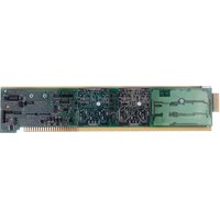
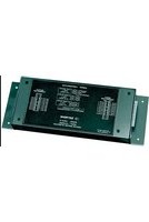
The optional Model 10CAI-8 Eight-Channel Buffer Interface can convert one or more of the Model 10AAO-8's eight voltage outputs to standard ISA current signals, either unipolar (4 to 20 mA) or bipolar ("zero-center," 4 to 12 to 20 mA). This externally mounted buffer unit can also amplify one or more of the 10AAO-8's ±5-V outputs to the ±10-V range.
Note that the MODEL 10A79-4 FOUR-CHANNEL ANALOG PEAK CAPTURE CARD can be used to provide up to four continuous, unscaled voltage outputs for "real-time" representation of analog signals produced by conditioner cards or other internal system elements, while the MODEL 10AAO-4 ANALOG BUFFER CARD can provide scaled buffering of such outputs. See Section 3.A.7 of this Guidebook.
1. MODEL 10AAO-8 CONNECTIONS
The Model 10AAO-8's 20-pin rear I/O CONNECTOR mates with Daytronic CONDITIONER CONNECTOR No. 60322 (shown in Fig. 1.E.1). Pin functions are given in Table 3.A.2.1, below.
As shown in Fig. 3.A.2.1, ALL ANALOG OUTPUTS ARE SINGLE-ENDED, AND RETURN TO "SYSTEM COMMON."
Fig. 3.A.2.1 Model 10AAO-8 Cabling

flowchart
graph TD
    A["EXTERNAL DEVICE (±5 V)"] -->|+| B["CONDITIONER CONNECTOR (No. 60322)"]
    A -->|-| B
    B --> C["SHIELD"]
    C --> D["Ground Lug"]
    D --> E["Connector pins shown as viewed from rear(cable) side of connector."]
    subgraph Channel1
        F["CHANNEL 1"] --> G["+"]
    end
    subgraph Channel2
        H["CHANNEL 2"] --> I["A"]
        J["CHANNEL 3"] --> K["B"]
        L["CHANNEL 4"] --> M["C"]
        N["CHANNEL 5"] --> O["D"]
        P["CHANNEL 6"] --> Q["E"]
        R["CHANNEL 7"] --> S["F"]
        T["CHANNEL 8"] --> U["H"]
        V["CHANNEL 9"] --> W["J"]
        X["CHANNEL 10"] --> Y["L"]
    end
    style Channel1 fill:#f9f,stroke:#333
    style Channel2 fill:#ccf,stroke:#333
Table 3.A.2.1.
Model 10AAO-8 Pin Assignments
| I/O CONNECTOR Pin No. | 10AAO-8 Chan. No. | Line Function | I/O CONNECTOR Pin No. | 10AAO-8 Chan. No. | Line Function |
| 1 | 1 | SIGNAL | 5 | 5 | SIGNAL |
| A | 1 | COMMON | E | 5 | COMMON |
| 2 | 2 | SIGNAL | 6 | 6 | SIGNAL |
| B | 2 | COMMON | F | 6 | COMMON |
| 3 | 3 | SIGNAL | 7 | 7 | SIGNAL |
| C | 3 | COMMON | H | 7 | COMMON |
| 4 | 4 | SIGNAL | 8 | 8 | SIGNAL |
| D | 4 | COMMON | J | 8 | COMMON |
Pins 9 through L are not committed.
2. CONFIGURATION OF ANALOG OUTPUT CHANNELS
An ANALOG OUTPUT may be assigned any "legal" Channel Number (1 through 997). ANALOG OUTPUT CHANNELS and ANALOG INPUT (or "DATA") CHANNELS may be intermixed as desired in the Channel-Number sequence.
Like all "REAL" DATA CHANNELS, all ANALOG OUTPUT CHANNELS must be initially "typed" and "located." For an introductory discussion of channel TYPES and LOCATIONS, see Section 1.G.2 of this Guidebook.
IF YOUR DATAPAC HAS BEEN SHIPPED WITH ONE OR MORE MODEL 10AAO-8 CARDS ALREADY INSTALLED, THE CORRESPONDING ANALOG OUTPUTS WILL HAVE BEEN CONFIGURED AT THE FACTORY, IN ACCORDANCE WITH SPECIFICATIONS GIVEN AT THE TIME OF ORDER. In this case, you need only refer to the customized "System 10 Data Sheet" in Appendix A of this Guidebook, for the TYPE and LOCATION designations presently in effect for these channels.
In the event, however, that you need to reconfigure an existing ANALOG OUTPUT CHANNEL, or to configure ANALOG OUTPUTS for a newly installed 10AAO-8, you should observe the following procedure:
a. SETTING CHANNEL TYPE: ANO COMMAND
Like certain kinds of PSEUDOCHANNELS, ANALOG OUTPUT CHANNELS are "autotyping." That is, the application of one of the two forms of the ANALOG OUTPUT (ANO) command will automatically inform the DataPAC's CENTRAL PROCESSOR of the appropriate TYPE designation for that channel:
- The TYPE code for an ANALOG OUTPUT "sourced" by a command of ANO x = m(CHN y) + b [CR] * is "E0."
- The TYPE code for an ANALOG OUTPUT "sourced" by a command of ANO x = [CONSTANT] [CR] * is "E1."
Besides "typing" the ANALOG OUTPUT CHANNEL in question, the ANO command serves to specify the "data source" for that output, and may be reapplied any number of times following initial configuration of the channel. This command is discussed in detail below. Here you need only note that when an ANALOG OUTPUT CHANNEL is being configured, the application of one of the two forms of the ANO command should always precede application of the LOCATE (LCT) command (below).
b. SETTING CHANNEL LOCATION: LCT COMMAND
Each ANALOG OUTPUT must be physically "located" with reference to an installed Model 10AAO-8 Card. The procedure is identical to that for the "locating" of system "REAL" CHANNELS. The general form of the LOCATE (LCT) command is
$$ \mathbf {L C T} \mathbf {x} = \mathbf {s} [ \mathbf {C R} ] ^ {*} $$
where "x" is the number of the ANALOG INPUT/OUTPUT CHANNEL being "located," and "s" is an appropriate LOCATION number: SLOT and SUBCHANNEL for "A-sized" DataPACs; DECK, SLOT, and SUBCHANNEL for "B-sized" DataPACs. See Section 1.G.2(d) and Appendix C for more details.
For example, if you wish system Channel No. 7 to be the ANALOG OUTPUT issued by Subchannel No. 4 of the Model 10AAO-8 occupying Slot No. 11 of a Model 10K6 DataPAC's A-CARD Deck No. 2, then the appropriate LOCATE (LCT) command would be
$$ \text { LCT } 7 = 2 1 1 4 [ \mathrm{CR} ] ^ {*} $$
NOTE: Application of one of the two forms of the ANO command to a given channel should always precede application of the LOCATE (LCT) command to that channel. ALSO, YOU SHOULD NEVER APPLY THE TYPE (TYP) COMMAND TO AN ANALOG OUTPUT CHANNEL.
3.A.2 Voltage and Current Outputs
3. SETTING ANALOG OUTPUT "SOURCE": ANO COMMAND
a. SETTING ANALOG OUTPUT EQUAL TO A FIXED MILLIVOLT VALUE
To establish a fixed millivolt value as the "data source" for ANALOG OUTPUT CHANNEL No. x, and to assign a TYPE code of "E1" to that channel, command
$$ \mathbf {A N O} \mathbf {x} = \mathbf {e} [ \mathbf {C R} ] ^ {*} $$
where "e" is the desired output value in millivolts (allowable range is ± 5000 mV).
For example, commanding
$$ \text { ANO } 3 = 3 5 0 0 [ \mathrm{CR} ] ^ {*} $$
will yield a constant output of 3.500 volts (±1 mV) for ANALOG OUTPUT CHANNEL No. 3.
NOTE
The entered "e" value is automatically stored in EEPROM, and becomes, in effect, the powerup default value for the ANALOG OUTPUT CHANNEL in question. While you can at any time specify a new "source" value "e" simply by reapplying the ANO command, this is a SETUP operation, and requires that the EEPROM Write Protect Switch be ON.
For temporary "RUN-TIME" modification of an existing fixed ANALOG OUTPUT value, you can regard the ANALOG OUTPUT CHANNEL as a form of VOLATILE DOWNLOAD PSEUDOCHANNEL and use the "WRITE" form of the CHANNEL (CHN) command, as explained in Section 2.D.2.
Thus, returning to the above example, a "RUN-TIME" COMMAND of
$$ \mathrm{CHN} 3 = 2 2 0 0 [ \mathrm{CR} ] $$
will change the value of the voltage output of Channel No. 3 from 3.500 V (specified during "setup" by the ANO command) to 2.200 V. Note, however, that the original EEPROM-stored "source" value of 3500 mV will again become effective, by default, as soon as system power is cycled.
b. SETTING ANALOG OUTPUT AS A FUNCTION OF A SYSTEM DATA CHANNEL
To establish any system DATA CHANNEL No. y as the "data source" for ANALOG OUTPUT CHANNEL No. x, and to assign a TYPE code of "E0" to Channel No. x, command
$$ \mathbf {A N O} \mathbf {x} = \mathbf {m} (\mathbf {C H N} \mathbf {y}) + \mathbf {b} [ \mathbf {C R} ] $$
where "m" and "b" are floating-point constants to convert the engineering units of Channel No. y to millivolts, for output by Channel No. x (allowable range is again ± 5000 mV).
This form of the ANO command causes ANALOG OUTPUT CHANNEL No. x to continuously reflect the existing value of the "Source" Channel No. y.
C. INTERROGATING FOR "SOURCE" AND VALUE OF AN ANALOG OUTPUT
You may at any time request the "data source" for a given ANALOG OUTPUT CHANNEL No. x by commanding
$$ \mathbf {A N O} \times [ \mathbf {C R} ] $$
Depending on the nature of the ANO command used to initialize the channel, the DataPAC will answer with either a fixed millivolt value ("e") or a linear expression ("m(CHN y) + b").
Regardless, however, of the source from which its reading is derived, you can always request the current millivolt value of ANALOG OUTPUT CHANNEL No. x by simply commanding
$$ \mathbf {C H N} \times [ \mathbf {C R} ] $$
(For more information on the CHANNEL (CHN) interrogation, see Section 1.H.2.)
d. CANCELLING AN ANALOG OUTPUT: RST COMMAND
To cancel the current ANALOG OUTPUT assignment for Channel No. x, enter a RESET (RST) command of
$$ \mathbf {R S T} \times [ \mathbf {C R} ] ^ {*} $$
This will reset the "TYPE" code for Channel No. x to "D0" (VOLATILE DOWNLOAD PSEUDOCHANNEL). A subsequent interrogation of ANO x [CR] will receive an answer of N/A. Note that the "WRITE" form of the TYPE (TYP) command will have no effect on an ANALOG OUTPUT CHANNEL.
1. 10CAI-8 CONNECTIONS
The eight channels of the Model 10CAI-8 operate individually on the eight ± 5-volt outputs of the Model 10AAO-8 Voltage Output Card. Each 10CAI-8 channel is independently programmable for full-scale representation as
a. 4 to 20 mA, corresponding to a 10AAO-8 output of 0 to +5 V-DC;
b. 4 to 12 to 20 mA, corresponding to a 10AAO-8 output of -5 to +5 V-DC; or
c. ±10 V-DC, corresponding to a 10AAO-8 output of -5 to +5 V-DC.
Interconnections between the Model 10CAI-8 and the Model 10AAO-8 are shown in Fig. 3.A.2.2. Cabling between the 10AAO-8's rear I/O CONNECTOR and the 10CAI-8's "INPUT CONNECTOR" is pin-to-pin. At its "OUTPUT CONNECTOR," the 10CAI-8 provides eight analog signals—current or voltage—in a one-to-one correspondence to the eight outputs of the 10AAO-8. Pin assignments for the 10CAI-8's "OUTPUT CONNECTOR" are identical to those of the 10AAO-8's I/O CONNECTOR (see Table 3.A.2.2, above).
As shown in Fig. 3.A.2.2, ALL 10AAO-8 OUTPUTS ARE SINGLE-ENDED, AND RETURN TO "SYSTEM COMMON."
Fig. 3.A.2.2 10AAO-8/10CAI-8 Interconnections

flowchart
graph TD
    A["CONDITIONER CONNECTOR (No. 60322) Model 10AAO-8"] --> B["SHIELD"]
    B --> C["POWER INPUT CONNECTOR"]
    C --> D["AC POWER (110 or 220 V)"]
    E["EXTERNAL DEVICE (4-20 mA or ±10 V)"] --> F["OUTPUT CONNECTOR"]
    F --> G["INPUT CONNECTOR"]
    G --> H["CHANNEL 1"]
    G --> I["CHANNEL 2"]
    G --> J["CHANNEL 3"]
    G --> K["CHANNEL 4"]
    G --> L["CHANNEL 5"]
    G --> M["CHANNEL 6"]
    G --> N["CHANNEL 7"]
    G --> O["CHANNEL 8"]
    P["Ground Lug"] --> Q["Connector pins shown as viewed from rear(cable) side of connector."] --> R["SHIELD"]
    S["CHANNEL 1"] --> T["A 1"]
    S --> U["B 2"]
    S --> V["C 3"]
    S --> W["D 4"]
    S --> X["E 5"]
    S --> Y["F 6"]
    S --> Z["H 7"]
    S --> AA["J 8"]
    S --> AB["K 9"]
    S --> AC["L 10"]
    AD["CHANNEL 1"] --> AE["A 1"]
    AD --> AF["B 2"]
    AD --> AG["C 3"]
    AD --> AH["D 4"]
    AD --> AI["E 5"]
    AD --> AJ["F 6"]
    AD --> AK["H 7"]
    AD --> AL["J 8"]
    AD --> AM["K 9"]
    AD --> AN["L 10"]
    AO["CHANNEL 2"] --> AP["A 1"]
    AO --> AQ["B 2"]
    AO --> AR["C 3"]
    AO --> AS["D 4"]
    AO --> AT["E 5"]
    AO --> AU["F 6"]
    AO --> AV["H 7"]
    AO --> AW["J 8"]
    AX["CHANNEL 3"] --> AY["A 1"]
    AX --> AZ["B 2"]
    AX --> BA["C 3"]
    AX --> BB["D 4"]
    AX --> BC["E 5"]
    AX --> BD["F 6"]
    AX --> BE["H 7"]
    AX --> BF["J 8"]
    AX --> BG["K 9"]
    AX --> BH["L 10"]
Every 10CAI-8 box requires its own AC power supply. A six-foot power cord comes with every unit, with a switch-selectable transformer that may be plugged into any standard 110-VAC or 220-VAC source (60 Hz). The power cord jack fits into the hole beside the 10CAI-8's "INPUT CONNECTOR."
2. PROGRAMMING OF 10CAI-8 OUTPUTS
a. Disconnect the 10CAI-8's AC power supply.
b. Remove the top plate of the 10CAI-8 box (4 screws in corners).
C. Locate the double row of programming jumper pins for each of the 10CAI-8's eight channels. The Channel Number is printed to the immediate left of each pin block. Each pair of pins in each block is labelled by letter (A, B, C, D, or E).
Fig. 3.A.2.3 Jumper Configurations for 10CAI-8 Outputs (EACH CHANNEL INDEPENDENTLY PROGRAMMABLE)
a) For 4-20 mA Output

b) For 4-12-20 mA Output

c) For ± 10 V-DC Output

d. To configure each channel for the desired form of output, you will connect appropriate pin pairs as shown in Fig. 3.A.2.3, by means of "mini-jumpers" or wires (four "mini-jumpers" are supplied with the 10CAI-8):
- 4-20 mA OUTPUT
Connect pin pairs "B" and "E" for every 10CAI-8 channel you want to yield unipolar current output (4-20 mA).
- 4-12-20 mA OUTPUT
Connect pin pairs "C" and "E" for every 10CAI-8 channel you want to yield bipolar current output (4-12-20 mA).
- ±10-V OUTPUT
Connect pin pairs "A" and "D" for every 10CAI-8 channel you want to yield ± 10-volt (DC) output.
3.A.2 Voltage and Current Outputs



- MODEL 10AAO-8 CONNECTIONS
- CONFIGURATION OF ANALOG OUTPUT CHANNELS
- a. SETTING CHANNEL TYPE: ANO COMMAND
- b. SETTING CHANNEL LOCATION: LCT COMMAND
- 3.A.2 Voltage and Current Outputs
- SETTING ANALOG OUTPUT "SOURCE": ANO COMMAND
- a. SETTING ANALOG OUTPUT EQUAL TO A FIXED MILLIVOLT VALUE
- NOTE
- b. SETTING ANALOG OUTPUT AS A FUNCTION OF A SYSTEM DATA CHANNEL
- INTERROGATING FOR "SOURCE" AND VALUE OF AN ANALOG OUTPUT
- d. CANCELLING AN ANALOG OUTPUT: RST COMMAND
- 10CAI-8 CONNECTIONS
- PROGRAMMING OF 10CAI-8 OUTPUTS
Brand : Daytronic
Model : 10CAI-8
Category : Electronic board