
10A10-4 - Electronic board Daytronic - Free user manual and instructions
Find the device manual for free 10A10-4 Daytronic in PDF.


| Product Type | Precision Thermocouple Conditioner Module |
| Model | 10A10-4 |
| Number of Channels | 4 independent channels |
| Supported Thermocouple Types | B, E, J, K, R, S, T (any mixture) |
| Input Isolation | Transformer-isolated, sensor-to-chassis/sensor-to-sensor common-mode up to 1500 VDC / 1000 VAC (rms) at 60 Hz |
| Common Mode Rejection Ratio (DC) | -154 dB |
| Common Mode Rejection Ratio (60 Hz) | -160 dB |
| Input Impedance (Differential) | 10 MΩ |
| Input Impedance (Common Mode) | Infinite |
| Amplifier Offset | Initial: ±5 μV; vs. Temp: ±0.1 μV/°C; vs. Time: ±1 μV/month |
| Gain Accuracy | ±0.02% of absolute mV input range (-10 to +80 mV) |
| Filter | 3-pole modified Butterworth, 3 dB at 1 Hz, 60 dB at 60 Hz |
| Step Response Settling Time (to 0.02%) | 1.5 sec |
| Reference-Junction Compensation | Built-in precision thermistor in connector, or optional remote with 10CTJB-8 |
| Thermocouple Break Detection | Automatic, off-scale negative indication |
| Linearization | Internal digital look-up via system processor, max error ±0.05°C |
| Total System Accuracy (typical) | Varies by thermocouple type (see manual table), e.g., Type E: ±0.4°C at 0.1°C resolution |
| Operating Environment | Intended for use with Daytronic System 10; requires Model 10A11 Output Processor Card |
| Connector | Rear-panel screw terminals for TC leads (no soldering); 20-pin I/O connector |
| Optional Accessory | Model 10CTJB-8 Thermocouple Junction Box for remote reference junction (ambient: 0°F to +140°F) |
Frequently Asked Questions - 10A10-4 Daytronic
User questions about 10A10-4 Daytronic
0 question about this device. Answer the ones you know or ask your own.
Ask a new question about this device
Download the instructions for your Electronic board in PDF format for free! Find your manual 10A10-4 - Daytronic and take your electronic device back in hand. On this page are published all the documents necessary for the use of your device. 10A10-4 by Daytronic.
USER MANUAL 10A10-4 Daytronic
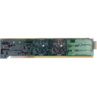
The Model 10A10-4 is a precision conditioner designed for TC-based temperature measurements requiring high input isolation. With built-in reference-junction compensation, it accepts up to four independent temperature signals from Types B, E, J, K, R, S, and T Thermocouples. Any desired mixture of these thermocouple types is permitted. Sensors may be grounded or ungrounded, in any desired mix. An amplifier-per-channel design with chopper stabilization and active low-pass filtering allows high-speed scan switching of high-level, stabilized signals, at exceptionally low cost per channel.
All four 10A10-4 inputs are transformer-isolated, so that sensor-to-chassis and/or sensor-to-sensor common-mode voltages as high as 1500 V-DC can be accommodated at DC or low frequencies without damaging the instrument or perceptibly affecting measurement accuracy (at 60 Hz, the common-mode voltage can be as high as 1000 V-AC (rms)).
During operation, appropriate reference-junction compensation, real-time digital linearization, and engineering-unit scaling are automatically applied by the System 10 Central Processor for each type of thermocouple used. Detection of “open” thermocouples is also provided, as explained in Section 3.a.
The Model 10A10-4 includes a rear-panel connector block with screw terminals for direct attachment of TC leads (which cannot be soldered). The same connector accommodates all TC types. Since the connector assembly also contains a dual-bead precision thermistor for measurement of the reference-junction temperature, no external cold junction is required—although the user may supply his own Controlled Ambient Temperature Zone for reference-junction compensation, if desired.
The reference-junction-corrected temperature is made available to the Central Processor through the Model 10A11 Thermocouple Output Processor Card. The purpose of the 10A11 is to proportion and sum the cold-junction reference signal and the amplified TC signal of each channel for presentation to the system's Analog Signal Bus. One 10A11 must therefore be installed in every System 10 A-card rack containing one or more Model 10A10-4's.
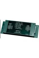
You can use an optional Model 10CTJB-8 Thermocouple Junction Box with a Model 10A10-4 to move the temperature-compensated reference junction to the actual site of up to eight remote thermocouple sensors. As explained in Section 4, below, TC leads connect directly to the 10CTJB-8's internal screw terminals, in any desired type mixture. The Junction Box then sends their signals to the 10A10-4 Conditioner via copper conductors (only).*
ADDITIONAL 10A10-4 SPECIFICATIONS
Measurement Range and Resolution: See Table 1, below; automatically selected—on an individual channel basis—when the channel is configured; for System 10 channel “type” codes assigned to 10A10-4 data channels, see Table 1
Linearization: Internal digital look-up via system processor; maximum error: ±0.05°C
Reference-Junction Compensation: At connector block, using a built-in precision thermistor, or at remote TC site, using the Model 10CTJB-8 Thermocouple Junction Box*
Thermocouple Break Detection (per channel): Off-scale negative indication
Amplifier (per channel):
Common-Mode Range: At DC, ±1500 V-DC operating and without instrument damage; at 60 Hz, ±1000 V-AC (rms) without damage
Common-Mode Rejection Ratio: DC: -154 dB; at 60 Hz: -160 dB
Input Impedance: Differential: 10 MΩ; Common-Mode: infinite
Offset: Initial: ±5 μV; vs. Temperature: ±0.1 μV/°C; vs. Time: ±1 μV/month
Gain Accuracy: ±0.02% of absolute mV input range of -10 to +80 mV
Gain Stability: vs. Temperature: ±25 ppm/°C; vs. Time: ±20 ppm/month
Filter (per channel): 3-pole modified Butterworth; 3 dB down at 1 Hz; 60 dB down at 60 Hz
Step-Response Settling Time (Full-Scale Output):
To 1% of final value: 0.3 sec
To 0.1% of final value: 0.6 sec
To 0.02% of final value: 1.5 sec
Total System Accuracy (typical, including Model 10A10-4, Model 10A11 Thermocouple Output Processor, and system data collection and processing): see Table 1, below
Auxiliary Outputs to Mainframe Wire-Wrap Pins: None
Table 1 Thermocouple Ranges for the Model 10A10-4
| TC Display System Expected Type | Typical Maximum Channel | ||||
| Type Range Resolution Accuracy** | Code | ||||
| E | -130°C to +1000°C | 0.1°C | ±0.4°C | ±0.6°C | 20 |
| J | -130°C to +750°C | 0.1°C | ±0.5°C | ±0.7°C | 21 |
| K | -75°C to +1350°C | 0.1°C | ±0.7°C | ±1.1°C | 22 |
| R | -20°C to +1750°C | 0.1°C | ±1.1°C | ±2.1°C | 23 |
| S | -20°C to +1750°C | 0.1°C | ±1.1°C | ±2.1°C | 24 |
| T | -130°C to +400°C | 0.1°C | ±0.5°C | ±0.8°C | 25 |
| B | +480°C to +1820°C | 0.1°C | ±1.1°C | ±2.1°C | 26 |
| E | -200°F to +1800°F | 0.2°F | ±0.8°F | ±1.2°F | 28 |
| J | -200°F to +1400°F | 0.2°F | ±0.8°F | ±1.2°F | 29 |
| K | -100°F to +2500°F | 0.2°F | ±1.2°F | ±2.0°F | 2A |
| R | 0°F to +3200°F | 0.2°F | ±2.0°F | ±3.8°F | 2B |
| S | 0°F to +3200°F | 0.2°F | ±2.0°F | ±3.8°F | 2C |
| T | -200°F to +750°F | 0.2°F | ±0.8°F | ±1.2°F | 2D |
| B | +900°F to +3300°F | 0.2°F | ±2.0°F | ±3.8°F | 2E |
| (cont'd) | |||||
* The 10CTJB-8 can only be used in environments with an ambient temperature between 0^ and +140^ .
** Including ± one count of least significant digit displayed. Can be readily improved by control of instrument temperature, calibrating at known temperatures, etc.
Typical Maximum Channel
TC Display System Expected Type
Type Range Resolution Accuracy* Error* Code
| E | - | 130°C to +1000°C | 1°C ±1°C ±2°C 10 | |||
| J | - | 130°C to +750°C | 1°C ±1°C ±2°C 11 | |||
| K -75°C to +1350°C | 1°C ±1°C ±2°C 12 | |||||
| R -20°C to +1750°C | 1°C ±2°C ±3°C 13 | |||||
| S -20°C to +1750°C | 1°C ±2°C ±3°C 14 | |||||
| T | -130°C to +400°C | 1°C ±1°C ±2°C 15 | ||||
| B +480°C to +1820°C | 1°C ±2°C ±3°C 16 | |||||
| E | -200°F to +1800°F | 1°F | ±1°F | ±2°F | 18 | |
| J | -200°F to +1400°F | 1°F | ±1°F | ±2°F | 19 | |
| K | -100°F to +2500°F | 1°F | ±2°F | ±3°F | 1A | |
| R | 0°F to +3200°F | 1°F | ±2°F | ±4°F | 1B | |
| S | 0°F to +3200°F | 1°F | ±2°F | ±4°F | 1C | |
| T | -200°F to +750°F | 1°F | ±1°F | ±2°F | 1D | |
| B | +900°F to +3300°F | 1°F | ±2°F | ±4°F | 1E | |
2
TRANSDUCER CONNECTIONS
The Model 10A10-4's I/O CONNECTOR mates with Daytronic CONDITIONER CONNECTOR No. 60324, similar to the one shown in Fig. 1.5 (in Manual Section 1.E.1). This connector contains four “±” screw-terminal pairs, one for each TC sensor. Each TC lead should be directly attached to its corresponding screw terminal (it should never be soldered). As shown in Fig. 1, each screw terminal connects internally to a specific pin on the 10A10-4's rear 20-pin I/O CONNECTOR. Table 2 gives standard pin assignments for the I/O connector. For connection of an optional Model 10CTJB-8 Thermocouple Junction Box, see Section 4, below.
Since reference-junction compensation is provided by the dual-bead thermistor embedded in the Conditioner Connector, no external cold junction is required.
IMPORTANT: UNUSED THERMOCOUPLE INPUT CHANNELS should be shorted together as shown in Fig. 2, to prevent possible crosstalk from the "OPEN TC" detection circuit into working TC channels.
Table 2 Model 10A10-4 Pin Assignments
| I/O Connector Pin Number | Screw Terminal | Conditioner Conditioner Channel Number | Line Function |
| 1 | 1(+) | 1 | +SIGNAL |
| A | 1(-) | 1 | -SIGNAL |
| 2 | Not Committed | ||
| B | Not Committed | ||
| 3 | 3(+) | 2 | +SIGNAL |
| C | 3(-) | 2 | -SIGNAL |
| 4 | Not Committed | ||
| D | Not Committed | ||
| 5 | 5(+) | 3 | +SIGNAL |
| E | 5(-) | 3 | -SIGNAL |
| 6 | Not Committed | ||
| F | Not Committed |
(cont'd)
* Including ± one count of least significant digit displayed. Can be readily improved by control of instrument temperature, calibrating at known temperatures, etc.
I/O Connector Conditioner Conditioner Pin Screw Channel Line
| Number Terminal Number | Function | ||
| 7 | 7(+) | 4 | +SIGNAL |
| H | 7(-) | 4 | -SIGNAL |
| 8 | Not Committed | ||
| J | Not Committed | ||
| 9 | INTERNAL | THERMISTOR: T1 | |
| K,L | USE | THERMISTOR: GROUND (COMMON) | |
| 10 | ONLY | THERMISTOR: T2 | |


3 SETUP AND/OR OPERATING CONSIDERATIONS
3.a "OPEN TC" DETECTION
In the event of a broken thermocouple wire or other “open TC” condition, the Model 10A10-4 will automatically report an indeterminate negative off-scale reading for the TC channel in question.
3.b CONFIGURATION AND CALIBRATION
For initial configuration of ANALOG INPUT CHANNELS dedicated to a specific Model 10A10-4 card, see the general remarks on System 10 "real-channel" configuration in Manual Section 1.G.1 and elsewhere in the System 10 Guidebook. For 10A10-4 channel "type" codes, see Table 1, above.
REMEMBER: One Model 10A11 Thermocouple Output Processor Card must be installed in every A-card deck that contains one or more Model 10A10-4 cards. Note that Model 10A10-4 and Model 10A9-8C cards can share a single 10A11.
The Model 10A10-4 normally employs CPU-BASED ABSOLUTE CALIBRATION (described in Manual Section 1.G.3.a). This means that NO calibration need be performed by the user, once each 10A10-4-based input channel has been properly configured. Note, however, that the standard ZERO (ZRO) and FORCE (FRC) commands can be used to perform TWO-POINT (DEADWEIGHT) CALIBRATION in applications where it is desirable to force multiple TC readings to the same exactly known temperature.* The mainframe's EEPROM Write Protect Switch must be ON for these commands to be effective. See Manual Section 1.G.5 for a general discussion of this conventional "zero and span" calibration technique.
4 OPTIONAL "REMOTE" TC CONNECTIONS: MODEL 10CTJB-8 THERMOCOUPLE JUNCTION BOX
4.a PURPOSE
You can use the Model 10CTJB-8 Thermocouple Junction Box with a Model 10A10-4 to move the temperature-compensated reference junction to the actual site of up to four remote thermocouple sensors.**
NOTE: The 10CTJB-8 can only be used in environments with an ambient temperature between 0^ F and +140^ F.
4.b CONNECTIONS
The label on the top side of the 10CTJB-8 box shows the numbering and polarity of the unit's eight internal screw-terminal pairs, which match those of the CONDITIONER CONNECTOR that attaches to the 10A10-4's rear I/O CONNECTOR (see Fig. 1 and the Pin-Assignment Table, above).
Introduced through the cutout on the left-hand side of the box, TC leads connect directly to these screw terminals, in any desired type mixture. The 10CJTB-8 then sends their signals to the Model 10A10-4 Conditioner Card via copper conductors (only).
The user must furnish his or her own pin-to-pin cable for connecting the 10CTJB-8 Junction Box to the rear I/O CONNECTOR of the Model 10A10-4. Daytronic will supply appropriate solder-terminal connectors for this cable. The cable should be shielded, and should consist of stranded copper wires. While no maximum cable length is actually specified, the wire size and length combination should be such that the total per-wire resistance does not exceed 25 ohms.



Brand : Daytronic
Model : 10A10-4
Category : Electronic board