
VCRB25 - Griddle Vulcan - Free user manual and instructions
Find the device manual for free VCRB25 Vulcan in PDF.


| Product type | Professional countertop gas plancha |
| Brand | Vulcan |
| Model | VCRB25 |
| Number of burners | 4 |
| Total heat output | 58,000 BTU/h |
| Compatible gas type | Natural gas or propane (convertible) |
| Supply pressure (natural gas) | 18 to 23 cm WC |
| Supply pressure (propane) | 28 to 30 cm WC |
| Grid material | Reversible durable cast iron |
| Radiant material | Cast iron |
| Ignition system | Standing pilot per burner |
| Controls | Individual heat control valves |
| Grease collector | Removable grease drawer |
| Leveling | Adjustable feet |
| Minimum distance to non-combustible walls | 8 cm at the rear and sides |
| Installation | Must be under a ventilation hood |
| Routine maintenance | Brush grids during cooking; clean with soapy water |
| Lubrication | Valves lubricated by qualified technician |
| Ventilation | Inspect and clean hood at least twice a year |
| Number of related models | VCRB36 (6 burners), VCRB47 (8 burners) |
Frequently Asked Questions - VCRB25 Vulcan
User questions about VCRB25 Vulcan
0 question about this device. Answer the ones you know or ask your own.
Ask a new question about this device
Download the instructions for your Griddle in PDF format for free! Find your manual VCRB25 - Vulcan and take your electronic device back in hand. On this page are published all the documents necessary for the use of your device. VCRB25 by Vulcan.
USER MANUAL VCRB25 Vulcan
natural_image
3D rendering of a white industrial electrical switchgear unit with multiple ports and mounting holes (no visible text or symbols)VCRB47
VCRB25
VCRB36
VCRB47
WCRB25
WCRB36
WCRB47
For additional information on Vulcan or to locate an authorized parts and service provider in your area, visit our website at www.vulcanequipment.com
IMPORTANT FOR YOUR SAFETY
THIS MANUAL HAS BEEN PREPARED FOR PERSONNEL QUALIFIED TO INSTALL GAS EQUIPMENT, WHO SHOULD PERFORM THE INITIAL FIELD START-UP AND ADJUSTMENTS OF THE EQUIPMENT COVERED BY THIS MANUAL.
POST IN A PROMINENT LOCATION THE INSTRUCTIONS TO BE FOLLOWED IN THE EVENT THE SMELL OF GAS IS DETECTED. THIS INFORMATION CAN BE OBTAINED FROM THE LOCAL GAS SUPPLIER.
IMPORTANT
IN THE EVENT A GAS ODOR IS DETECTED, SHUT DOWN UNITS AT MAIN SHUTOFF VALVE AND CONTACT THE LOCAL GAS COMPANY OR GAS SUPPLIER FOR SERVICE.
FOR YOUR SAFETY
DO NOT STORE OR USE GASOLINE OR OTHER FLAMMABLE VAPORS OR LIQUIDS IN THE VICINITY OF THIS OR ANY OTHER APPLIANCE.
WARNING
Improper installation, adjustment, alteration, service or maintenance can cause property damage, injury, or death. Read the installation, operating and maintenance instructions thoroughly before installing or servicing this equipment.
IN THE EVENT OF A POWER FAILURE, DO NOT ATTEMPT TO OPERATE THIS DEVICE.
INSTALLATION, OPERATION AND CARE OF MEDIUM DUTY GAS CHARBROILERS
GENERAL
Gas Countertop Charbroilers are designed for commercial use only and feature fast, efficient gas heat. Each burner is controlled by an adjustable gas valve. Cast radiants are located directly above each burner to maintain uniform temperature. Radiants are easily removed for cleaning when cool.
Heavy-duty, cast iron top grates are reversible to allow all or part of the cooking grid surface to be level or sloped. Grooves, cast in the top grates, permit fat runoff and reduce flaring when tilted towards the front. A grease drawer is provided to collect fat run-off; it opens to the front for inspection or drain-off.
| Model | Number Of Burners | BTU/hr Input Rating |
| VCRB25 / WCRB25 | 4 | 58,000 |
| VCRB36 / WCRB36 | 6 | 87,000 |
| VCRB47 / WCRB47 | 8 | 116,000 |
INSTALLATION
UNPACKING
This charbroiler was inspected before leaving the factory. The carrier assumes full responsibility for the safe delivery upon acceptance of the shipment. Check for possible shipping damage immediately after receipt.
If the charbroiler is found to be damaged, complete the following steps:
- Carrier must be notified within 5 business days of receipt.
- Carrier's local terminal must be notified immediately upon discovery (note time, date, and who was spoken to), and follow up and confirm with written or electronic communication.
- All original packing materials must be kept for inspection purposes.
- The charbroiler cannot have been moved, installed, or modified.
- Notify Vulcan Customer Service immediately at 800-814-2028.
Carefully unpack your charbroiler and make sure that no parts are discarded with packaging material. A pressure regulator designed to operate with the broiler has been supplied and must be installed before the charbroiler is placed into service (Refer to GAS PRESSURE REGULATOR INSTALLATION in this manual).
LOCATION
The installation location must be kept free and clear of combustibles. Do not obstruct the flow of combustion and ventilation air. DO NOT install the charbroiler adjacent to fryers unless following the provisions detailed by local codes and/or the applicable sections of ANSI-Z223.1/NFPA #54 (latest edition) and NFPA #96 (latest edition) in the United States of America or CAN/CSA 149.1 (latest edition) and CAN/CSA149.2 (latest edition) in Canada.
Sufficient air should be allowed to enter the room to compensate for the amount of air removed by any ventilating system and for combustion of the gas burners. Do not obstruct the air flow into and around the appliance. Do not obstruct the flow of flue gases through and above the broiler's top grate. Position the broiler in its final location. Check that there are sufficient clearances to service the broiler and to make the required gas supply connection(s). Provide 24" clearance at the front for cleaning, maintenance, service and proper operation.
This broiler is for use in non-combustible locations only. Installation in combustible locations is prohibited unless following the provisions detailed by local codes and/or the applicable sections of ANSI-Z223.1/NFPA #54 (latest edition) and NFPA #96 (latest edition) in the United States of America or CAN/CSA 149.1 (latest edition) and CAN/CSA149.2 (latest edition) in Canada and approved by the authority having jurisdiction.
Minimum clearances to non-combustible walls are 3" to the rear and 3" to the sides.
INSTALLATION CODES AND STANDARDS
The Charbroiler must be installed in accordance with:
In the United States of America:
- State and local codes.
- National Fuel Gas Code, ANSI-Z223.1/NFPA #54 (latest edition). This shall include but not be limited to: NFPA #54 Section 10.3.5.2 for Venting. Copies may be obtained from The American Gas Association Accredited Standards Committee Z223, @ 400 N. Capital St. NW, Washington, DC 20001 or the Secretary Standards Council, NFPA, 1 Batterymarch Park Quincy, MA 02169-7471
NOTE: In the Commonwealth of Massachusetts
All gas appliances vented through a ventilation hood or exhaust system equipped with a damper or with a power means of exhaust shall comply with 248 CMR.
- NFPA Standard # 96 Vapor Removal from Cooking Equipment, latest edition, available from the National Fire Protection Association, Batterymarch Park, Quincy, MA 02269.
In Canada:
- Local codes.
- CAN/CSA-B149.1 Natural Gas Installation (latest edition)
- CAN/CSA-B149.2 Propane Installation Code (latest edition), available from the Canadian Gas Association, 178 Rexdale Blvd., Etobicoke, Ontario, Canada M9W 1R3
BURNERS, RADIANTS, AND TOP GRATES
The top grates are shipped flat (top-side down) from the factory. For broiling, the top grates can be left in the flat position or reversed so they slope forward for grease run-off. Remove the cast iron grates and radiants. Inspect and remove the shipping restraints used during shipping to hold the burners. Reassemble the radiants and top grates. See Fig. 1.

LEVELING
It is important that the charbroiler is level front to back and left to right. Areas of uneven heat distribution will occur on an unleveled unit. The charbroiler is equipped with adjustable legs. Turn the feet at the bottom of the legs to adjust to level. The unit should be rechecked for level anytime it has been moved.
VENTILATION HOOD
The broiler should be installed under a suitable ventilation hood. For safe operation and proper ventilation, keep the space between the charbroiler and vent hood free from any obstructions.
GAS CONNECTION
NOTICE All gas supply connections and any pipe joint compound must be resistant to the action of propane gases.
Purge the supply line to clean out any dust, dirt, or any foreign matter before connecting the line to the unit.
Codes require that a gas shut-off valve be installed in the gas line ahead of the charbroiler. The gas supply line must be at least the equivalent of 34 " iron pipe.
A pressure regulator is supplied and must be installed outside of the broiler when making the gas supply connection. Standard orifices are set for 4"WC (Water Column) for Natural Gas — 10"WC (Water Column) for Propane. Use the ^1/_8 " pipe tap on the burner manifold for checking pressure. Make sure the gas piping is clean and free of obstructions, dirt, and piping compound.
An adequate gas supply is necessary. Undersized or low pressure lines will restrict the volume of gas required for satisfactory performance. A minimum supply pressure of 7" W.C. for natural gas and 11" W.C. for propane gas is recommended. With all units operating simultaneously, the manifold pressure on all units should not show any appreciable drop.
When testing the gas supply piping system, if test pressures exceed 12 psig (3.45 kPa), the charbroiler and its individual shutoff valve must be disconnected from the gas supply piping system. When test pressures are 12 psig (3.45 kPa) or less, the charbroiler must be isolated from the gas supply piping system by closing its individual manual shut-off valve during any pressure testing of the system.
WARNING Prior to lighting, check all joints in the gas supply line for leaks. Use soap and water solution. Do not use an open flame.
GAS PRESSURE REGULATOR INSTALLATION
This charbroiler is supplied with a convertible gas pressure regulator preset at 4" Water Column (W.C.) for natural gas. No further adjustment should be required. Install the regulator as close to the charbroiler on the gas supply line as possible. Make sure that the arrow on the underside of the regulator is oriented in the direction of gas flow to the charbroiler (Fig. 2) and the regulator is positioned with the vent plug and conversion plug cover upright (Fig. 3).

natural_image
Close-up of a metallic mechanical component with bolt holes and internal channels (no visible text or symbols)Fig. 2

natural_image
Close-up of a metallic mechanical valve component with bolt holes and mounting flanges (no visible text or symbols)Fig. 3
The minimum supply pressure (upstream of the regulator) should be 7-9" W.C. for natural gas and 11-12" W.C. for propane gas. At no time should the charbroiler be connected to supply pressure greater than 12 psig (3.45 kPa) or 14" W.C.
This charbroiler is shipped from the factory equipped with fixed burner orifices for natural gas operation. The burner orifices required to convert the charbroiler to propane gas are shipped with the charbroiler in the shipping packaging. It is recommended that a trained gas service technician with the necessary tools, instruments and skills perform the conversion.
To convert to propane, the following steps must be completed:
- Remove all natural gas burner orifices and install the provided propane burner orifices.
- Set the regulator to 10" W .C. by inverting regulator spring plug. See Fig. 4.

⚠ WARNING Prior to lighting, check all joints in the gas supply line for leaks. Use soap and water solution. Do not use an open flame.
CASTER EQUIPPED CHARBROILERS
Charbroilers mounted on stands with casters must use a flexible connector (not supplied) that complies with the Standard for Connectors for Movable Gas Appliances, ANSI Z21.69 • CSA 6.16 and a quick-disconnect device that complies with the Standard for Quick-Disconnect Devices for use With Gas Fuel, ANSI-Z21.41 • CSA 6.9. In addition, adequate means must be provided to limit movement of the broiler without depending on the connector and the quick-disconnect device or its associated piping to limit broiler movement. Attach the restraining device at the rear of the charbroiler. If disconnection of the restraint is necessary, turn off the gas supply before disconnection. Reconnect the restraint prior to turning the gas supply on and return the charbroiler to its installation position.
Note: If the Charbroiler is installed on casters and is moved for any reason, it is recommended that it be re-leveled (see LEVELING).
OPERATION
WARNING The charbroiler and its parts are hot. Use care when operating, cleaning or servicing the charbroiler.

Each burner is independently controlled by an infinite heat control valve. Once the pilots are lit, turning the control knob to the ON position will light each burner. The burners will be in the full ON position when the control knobs are turned all the way to the left. The burners will be in the full OFF position when the control knobs are turned all the way to the right. See Fig. 5.
There is one pilot for each burner. The charbroiler is equipped with standing, unmonitored pilots. Gas will flow from the pilots as soon as the main gas supply to the unit is turned on. See pilot lighting procedure on page 8.
Standing pilots should be adjusted to provide a slight yellow tip on the flame. Air shutters on the main burners must be individually adjusted to provide a blue flame. All traces of yellow should be adjusted out of the burner flame.
The charbroiler is a free vented appliance. All products of combustion and the heat generated by the burners pass through the grates. When meat is placed on the grates, this blocks the venting and causes a temperature build-up.
LIGHTING THE GAS PILOT
-
See Fig. 6. Turn main gas shut-o valve and the individual burner gas valves OFF. Wait 5 minutes.
-
Remove the top grates and radiants. Turn the main gas shut-o valve ON. Light pilots using a lit taper .Adjust the pilot valve screw (See Fig. 7 on page 9)unl the pilot ame has a slight yellow p.
-
To light the burners, turn the individual burner valves ON.
-
If the burners fail to light, turn all valves and the main gas shut-o to the OFF posion and contact an authorized service contractor.

FIG. 6
PILOT ADJUSTMENT
Using a flathead screwdriver, turn the slotted hex-head pilot adjustment screw clockwise to decrease the flame, and counterclockwise to increase the flame. See Fig. 7.

TO COMPLETELY SHUTDOWN THE BURNERS AND PILOT LIGHTS
For complete shutdown: Turn the main gas shut-off valve OFF. (Make sure all individual burner valves are off before relighting.)
PREHEATING THE CHARBROILER
Allow the charbroiler to preheat for 30 minutes. Rub grates with cooking oil before using.
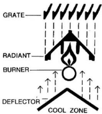
COMPONENT PARTS
The charbroiler comes with several standard parts as illustrated. Each can be easily removed and installed easily by hand for cleaning and maintenance. Note that the Burner and Deflector are an assembly and are NOT designed to be disassembled.
CLEANING
Scrape top grates during broiling with a wire brush to keep the grates clean. Do not allow debris to accumulate on the grates.
Top grates may be immersed in strong commercial cleaning compound overnight. In the morning, rinse with hot water to remove any residues of cleaning compound. Thoroughly dry and apply cooking oil to prevent rusting.
Stainless steel surfaces may be cleaned using damp cloth with mild detergent and water solution.
Places where fat, grease, or food can accumulate must be cleaned regularly.
NOTICE Never cover surface of unit with pans or other objects in attempt to "burn off" or clean debris from unit. This will cause a buildup of heat that can potentially damage and warp components of the charbroiler.
MAINTENANCE
WARNING The charbroiler and its parts are hot. Use care when operating, cleaning or servicing the griddle.
VENT SYSTEM
At least twice a year the exhaust hood (venting system) should be examined and cleaned.
LUBRICATION
All valves, at the first sign of sticking, should be lubricated by a trained technician using high temperature grease.
SERVICE
Contact your local Service Contractor for any repairs or adjustments needed on this equipment. For a complete listing of service and parts depots refer to www.vulcanequipment.com.
When calling for service, the following information should be available from the appliance identification plate: Model Number and Serial Number.
TROUBLESHOOTING
| Uneven heating, sides burning A. Burner valves improperly adjustedB. Fluctuating gas pressureC. Improperly adjusted burner | |
| Too much top heat A. Burner valves adjusted too highB. Faulty ventilationC. Overrated gas pressureD. Improperly adjusted burner | |
| Uneven heat side to side A. Burner valves improperly adjustedB. Appliance is not level side to sideC. Improperly adjusted burner | |
| Uneven heat front to back A. Appliance is not level front to backB. Faulty ventilationC. Improperly adjusted burner | |
| Pilot outage A. Pilot flame is set too low. Adjust pilot to allow for gas flow.B. Obstruction in pilot orificeC. Low gas pressure. | |
| Yellow burner flames A. Open burner shutters until flames are blue | |
| Lifting burner flames A. Close burner shutters until flames touch burner | |
| Fluctuating gas pressure A. Check for clogged vent on regulator |
NOTES
www.νulcanequipment.com.
natural_image
Close-up of a metallic mechanical component with bolts and housing (no visible text or symbols)Fig.2

natural_image
Close-up of a mechanical component with metallic parts and bolts (no visible text or symbols)INSTALLATION, EMPOLO ET ENTRETELEN DES
EN CAS DE PAVNE DE COUVAUT, NE PAS TENTER DE FAIRÉ FONCTIONNER CET APPAREL.
natural_image
3D rendering of a white industrial control panel with multiple slots and a mesh base (no visible text or symbols)MANUEL D'INSTALACTION ET D'EMPLOI POUR GRILS AU GAZ A FUNCTION MOYENNE
WOLF



- IMPORTANT FOR YOUR SAFETY
- IMPORTANT
- FOR YOUR SAFETY
- WARNING
- INSTALLATION, OPERATION AND CARE OF MEDIUM DUTY GAS CHARBROILERS
- GENERAL
- INSTALLATION
- UNPACKING
- LOCATION
- INSTALLATION CODES AND STANDARDS
- The Charbroiler must be installed in accordance with:
- NOTE: In the Commonwealth of Massachusetts
- BURNERS, RADIANTS, AND TOP GRATES
- LEVELING
- VENTILATION HOOD
- GAS CONNECTION
- GAS PRESSURE REGULATOR INSTALLATION
- CASTER EQUIPPED CHARBROILERS
- OPERATION
- LIGHTING THE GAS PILOT
- PILOT ADJUSTMENT
- TO COMPLETELY SHUTDOWN THE BURNERS AND PILOT LIGHTS
- PREHEATING THE CHARBROILER
- COMPONENT PARTS
- CLEANING
- MAINTENANCE
- VENT SYSTEM
- LUBRICATION
- SERVICE
- NOTES
- INSTALLATION, EMPOLO ET ENTRETELEN DES
- MANUEL D'INSTALACTION ET D'EMPLOI POUR GRILS AU GAZ A FUNCTION MOYENNE
Brand : Vulcan
Model : VCRB25
Category : Griddle