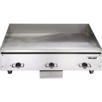
HEG36E - Griddle Vulcan - Free user manual and instructions
Find the device manual for free HEG36E Vulcan in PDF.


| Product Type | Griddle |
| Brand | Vulcan |
| Model | HEG36E |
| Category | Commercial Grill / Griddle |
| Dimensions (W x D x H) | 36 x 30 x 18 inches |
| Weight | 150 lbs |
| Power Source | Electric, 208V/240V, 3-phase |
| Total Power | 12 kW |
| Cooking Surface Material | Stainless steel with polished finish |
| Cooking Surface Dimensions | 36 x 24 inches |
| Temperature Control | Thermostatic control with 6 preset settings |
| Temperature Range | 200°F - 500°F |
| Number of Burners/Zones | 2 independently controlled zones |
| Grease Management | Front-mounted grease trough with removable drawer |
| Legs | 4 adjustable stainless steel legs with casters |
| Cleaning | Scrape with griddle scraper; season after cleaning |
| Safety Features | Over-temperature limit switch, power indicator light |
| Warranty | 1 year parts and labor, 5 year on burners |
| Certifications | NSF, UL, CSA |
Frequently Asked Questions - HEG36E Vulcan
User questions about HEG36E Vulcan
0 question about this device. Answer the ones you know or ask your own.
Ask a new question about this device
Download the instructions for your Griddle in PDF format for free! Find your manual HEG36E - Vulcan and take your electronic device back in hand. On this page are published all the documents necessary for the use of your device. HEG36E by Vulcan.
USER MANUAL HEG36E Vulcan
natural_image
Stylized black-and-white illustration of a wolf's head (no text or symbols)WOLF
HEG / RRE / WEG Series Griddle

natural_image
Two identical stainless steel laboratory equipment units with control knobs, no visible text or symbols.VULCAN HEG24E
HEG36E
HEG48E
HEG60E
HEG72E
RRE24E
RRE36E
RRE48E
WOLF WEG24E
WEG36E
WEG48E
WEG60E
WEG72E
This Manual is prepared for the use of trained Vulcan Service Technicians and should not be used by those not properly qualified.
This manual is not intended to be all encompassing. If you have not attended a Vulcan Service School for this product, you should read, in its entirety, the repair procedure you wish to perform to determine if you have the necessary tools, instruments and skills required to perform the procedure. Procedures for which you do not have the necessary tools, instruments and skills should be performed by a trained Vulcan Service Technician.
The reproduction, transfer, sale or other use of this Manual, without the express written consent of Vulcan, is prohibited.
This manual has been provided to you by ITW Food Equipment Group LLC (“ITW FEG”) without charge and remains the property of ITW FEG, and by accepting this manual you agree that you will return it to ITW FEG promptly upon its request for such return at any time in the future.
For additional information on Vulcan-Hart Company or to locate an authorized parts and service provider in your area, visit our website at www.vulcanequipment.com
TABLE OF CONTENTS
SERVICE UPDATES 3
SERVICE UPDATES 3
TIS DOCUMENT LIST - HEG / WEG SERIES 3
GENERAL 4
INTRODUCTION 4
MODELS COVERED 4
INSTALLATION 4
CLEANING PROCEDURES 4
TOOLS AND TEST EQUIPMENT 4
LUBRICATION 4
REMOVAL AND REPLACEMENT OF PARTS 5
GRIDDLE SERVICE POSITION 5
HEATING ELEMENT REPLACEMENT 5
THERMOSTAT REPLACEMENT 7
SERVICE PROCEDURES AND ADJUSTMENTS 9
THERMOSTAT CALIBRATION PROCEDURES 9
TESTING VOLTAGE TO HEATER(S) 10
- Added update to 60" WIRING DIAGRAM.
November, 2018
• Added TIS Document List.
August
TIS DOCUMENT LIST - HEG / WEG SERIES
| SERVICE TAB | |
| Document Title Document Type | |
| HEG-E / WEG-E Heavy Duty Electric Griddles Service Manual | Service Manual |
| SERVICE TAB (Multimedia) | |
| Document Title Document Type | |
| Repairing Flood-Damaged Food Equipment Misc | |
| HEG-E / WEG-E Heavy Duty Electric Griddles Operation & Installation Manual | Operator |
| Rating Plate Locations on Current Vulcan-Hart/Wolf Range Equipment | Technical Service Bulletin (TSB) |
| TSB 1037A Hobart to Vulcan "Common" Model Cross Reference List | Technical Service Bulletin (TSB) |
| PARTS TAB | |
| Document Title Document Type | |
| HEG-E / WEG-E Heavy Duty Electric Griddles Parts Catalog | Parts Catalog |
GENERAL
INTRODUCTION
This manual is applicable to the models and ML numbers on the cover page. Procedures apply to all models unless specified otherwise.
MODELS COVERED
| Vulcan Brand | ||
| Models Length | Depth | |
| HEG24E 24" 24" | ||
| HEG36E 36" 24" | ||
| HEG48E 48" 24" | ||
| HEG60E 60" 24" | ||
| HEG72E 72" 24" | ||
| Vulcan Brand | ||
| Models Length | Depth | |
| RRE24E 24" 24" | ||
| RRE36E 36" 24" | ||
| RRE48E 48" 24" | ||
| Wolf Brand | ||
| Models Length | Depth | |
| WEG24E 24" 24" | ||
| WEG36E 36" 24" | ||
| WEG48E 48" 24" | ||
| WEG60E 60" 24" | ||
| WEG72E 72" 24" | ||
INSTALLATION
Generally, all installation are made by the dealer or others contracted by the dealer or owner. Detailed installation instructions are included in the "Installation and Owners Manual" for the appropriate model.
CLEANING PROCEDURES
Detailed cleaning procedures are included in the "Installation and Owners Manual" for the appropriate model.
TOOLS AND TEST EQUIPMENT
Tools Required
- Standard set of hand tools.
• VOM with AC current tester.
NOTE: VOM sensitive of at least 20,000 ohms/volt can be used.
Special
- Thermocouple type, griddle or surface mount, temperature tester.
- 2 each, 8 inch long 4 × 4 wooden blocks.
LUBRICATION
- Anti seeing coumpound
- Penetrating oil
- Finger Nail Polish
OPERATING CONTROLS
Thermostat
With the dial set to the desired setting, the temperature of the griddle section is maintained. When the operator turns the thermostat dial to OFF, electrical power is removed from the heating unit. Each thermostat controls a 12 inch wide section of the griddle surface.
Indicator Light
A red light will energize automatically for each section of the griddle when the thermostat is set, and will de-energize when the section has reached the thermostat setting. The light will energize and de-energize during the cooking operation to show that current temperature is being maintained.
REMOVAL AND REPLACEMENT OF PARTS
GRIDDLE SERVICE POSITION
WARNING
Disconnect the electrical power to the machine and follow lockout / tagout procedures.
WARNING
Griddle plate might be hot.
Griddle Service Position
- Remove thermostat knobs.
- Remove front trim panel screws and remove front trim panel.
NOTICE
Do not damage indicator lights when removing front trim panel.
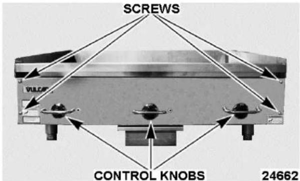
Fig. 1
- Remove griddle plate assembly mounting bolts, left and right side.
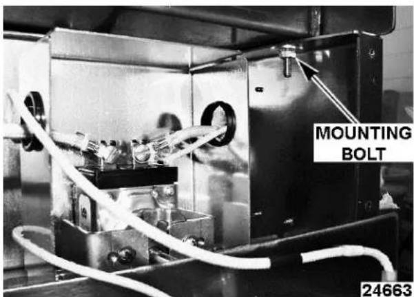
Fig. 2
WARNING
Lift griddle plate straight up to prevent the griddle plate from sliding to the left or right.
- Lift griddle plate up, to add two 4 x 4 blocks between the griddle plate and left and right sides of unit, approximately 6 to 7 inches.
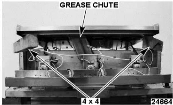
Fig. 3
NOTICE
Verify Grease Chute does not raise past the heater element panel. This helps prevent the top from sliding to the rear.
WARNING
Use 4 x 4, or greater, blocks to support griddle top. Do NOT use 2 x 4 blocks as they can tip over and lower griddle plate.
HEATING ELEMENT REPLACEMENT

WARNING
Disconnect the electrical power to the machine and follow lockout / tagout procedures.
WARNING
Griddle plate might be hot.
Heating Element Removal
- Place griddle plate into GRIDDLE SERVICE POSITION.
- Remove front heater element jumper wire connection.

Fig. 4
NOTICE
When removing heater element jumper wire screw, support heater element.

Fig. 5
- Remove element baffle shield.

Fig. 6
- Remove bulb clamp.
NOTE: Loosen front and rear bolts and remove thermostat probe from bulb clamp. Secure thermostat probe to prevent damage.
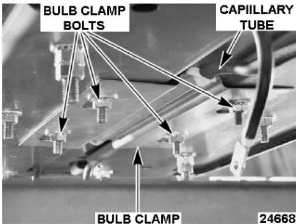
Fig. 7
- Remove heater element jumper wire on the back heater element connections.
NOTICE
When removing heater element jumper wire screw, support heater element. Refer to figure 24666.
- Remove heating element pressure plate.
NOTE: Heater element is held into place by the pressure plate.

Fig. 8
- Reverse procedures to install.
NOTE: Nuts should be torqued to 30-35 Inch Pounds.
- See THERMOSTAT REPLACEMENT for proper installation of the thermostat.
NOTE: Coat threaded studs with high temperature anti-seize compound prior to putting bolts back on.
NOTE: Tighten nuts to 30-35 inch-pounds.
NOTICE
Over tightening the nuts can cause damage and prevent the element from moving with expansion and contraction that can lead to premature failures.
- Check for proper operation.
THERMOSTAT REPLACEMENT
WARNING
Disconnect the electrical power to the machine and follow lockout / tagout procedures.
WARNING
Griddle plate might be hot.
Capillary Tube Removal
- Place griddle plate into GRIDDLE SERVICE POSITION.
- Remove front heater element jumper wire connection.
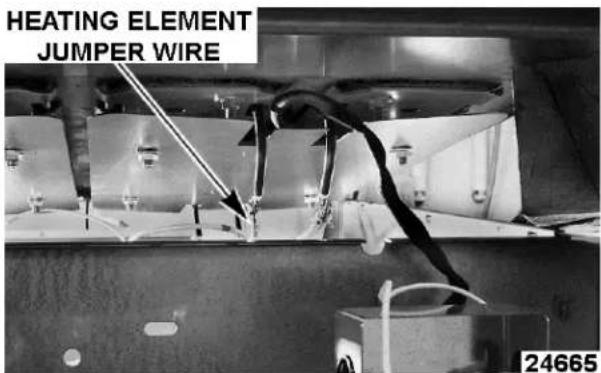
Fig. 9
NOTICE
When removing heater element jumper wire screw, support heater element.
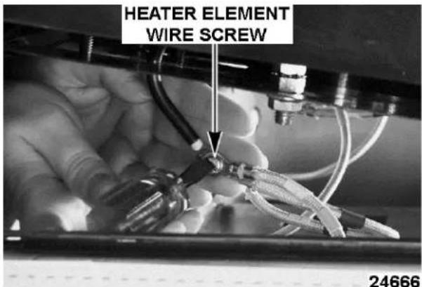
Fig. 10
- Remove heater element baffle shield.

Fig. 11
- Loosen back bolts to bulb clamp.
- Remove front bolts to bulb clamp.

Fig. 12
- Pull thermostat probe to remove. NOTE: Retain capillary sleeve for new thermostat.
Thermostat Control Removal
- Remove thermostat connection screws.
NOTE: Note heater element wire locations on the thermostat connection tabs. - Remove thermostat mounting screws.

Fig. 13
- Remove thermostat heat shield screws.
- Remove thermostat assembly from unit.
Thermostat Control Installation
- Install capillary sleeve on replacement thermostat.
- Install thermostat to thermostat bracket using mounting screws.
- Thread capillary tube through opening located on the thermostat heat shield.
NOTICE
Secure thermostat capillary tube to prevent damage, while installing thermostat.

Fig. 14
- Install thermostat bracket with the thermostat heat shield to the unit.
- Connect heater wires to the thermostat per the wire connections noted earlier.

Fig. 15
Capillary Tube Installation
- Slide capillary tube between bulb clamp and bottom of griddle plate.

Fig. 16
NOTE: Verify capillary tube is flush against the bottom of the griddle plate.
- Tighten bolts. Torque to 30-35 inch pounds.
- Install baffle shield using HEATING ELEMENT REPLACEMENT instructions.
- Check for proper operation.
SERVICE PROCEDURES AND ADJUSTMENTS
THERMOSTAT CALIBRATION PROCEDURES
- Clean temperature test section that is not working. Center temperature tester surface mount probe in center of thermostat probe. See table for proper testing locations according to griddle size.
NOTE: All readings taken 12" from front of griddle.
| Griddle Size | Distance(s) From Left Edge of Griddle |
| 24" 6", 18" | |
| 36" 6", 18", 30" | |
| 48" 6", 18", 30", 42" | |
| 60" 6", 18", 30", 42", 54" | |
| 72" 6", 18", 30", 42", 54", 66" |
- Set the thermostat to a temperature above 300^ F.
- Allow the thermostat to cycle three times.
- Note the tester reading when the indicator light turns ON and OFF.
NOTE: If the difference between the ON and OFF temperatures is greater than 25^ F, replace the thermostat.
- Add these two temperatures together, then divide the sum by 2 to obtain an average temperature.
A. If the average temperature is within 15^ F of the set temperature, the thermostat is calibrated.
B. If the average temperature is not within 15^ F of the set temperature:
1) Remove thermostat knob.
2) Insert a flathead screwdriver into thermostat dial stem until it reaches the calibration screw.

Fig. 17
3) Turn adjustment screw CCW to increase and CW to decrease temperature.
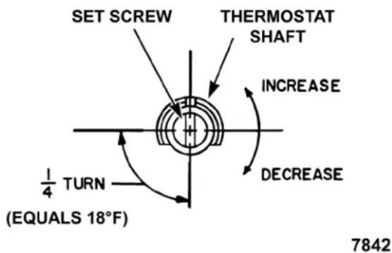
Fig. 18
NOTE: A 1/4 turn equals 18^ F change.
- Replace knob and repeat steps 3 and 5 until average temperature is within 15^ F of set temperature.
- Reseal adjustment screw to prevent movement.
NOTE: Finger nail polish can be used to reseal screw to prevent movement.
- If thermostat cannot be calibrated, replace thermostat as outlined under THERMOSTAT REPLACEMENT.
TESTING VOLTAGE TO HEATER(S)
WARNING
Disconnect the electrical power to the machine and follow lockout / tagout procedures.
- Test supply voltage to verify it is correct.
- Turn power off to griddle.
- Place griddle into GRIDDLE SERVICE POSITION.
- Connect voltmeter to leads of heating element in question.
-
Set meter on the appropriate range, determined by line voltage rating stamped on griddle data plate.
-
Turn on electrical power.
-
Turn thermostat to 350^ F.
A. Pilot light will energize.
- Reading should agree with the voltage rating stamped on the griddle data plate.
A. If voltage reading is incorrect, and the line voltage is correct, the thermostat is not functioning properly.
B. If current draw is correct, then heating element is functioning properly. See table below for proper values.
| VOLTS COLOR CODE POWER AMP RESISTANCE | ||||
| 208 YELLOW 2.7kW 13 16 | ||||
| 240 RED 2.7kW 11.3 21.3 | ||||
| 480 GREEN 2.7kW 5.6 | 85.7 | |||
| NOTES: | 1. Values in table are nominal. Tolerance is +5/-10%.2. Resistance values (ohms) are @ 77°F room temperature. | |||
-
Refer to the schematic in the appropriate electrical diagram at the end of this section to trace circuits explained in this section.
-
The electrical connection(s) to the griddle are made in the junction box.
A. Detailed information about the electrical connections to the griddle is contained in the "Installation and Owners Manual".
-
From the junction box, one electrical connection is made to the thermostat. The other electrical connection is made to the common side of the two heating elements which the thermostat controls.
-
With the dial set to "OFF", the thermostat contacts are open.
-
Turn dial to 350^ F.
A. The thermostat contacts close, electrical power is applied to the heating elements, the griddle begins to heat.
B. The indicator light energizes.
- When the griddle surface reaches 350^ F, the thermostat contacts open and electrical power is removed from the heating elements.
A. The indicator light de-energizes.
- The thermostat will cycle the heating elements and indicator light to maintain the griddle temperature.
24" WIRING DIAGRAM

24" WIRING DIAGRAM
Notes:
- For supply connections, use copper wire sized in accordance with the national electrical code and suitable for at least 90°C (194°F).
- Lead marker numbers are the same as lead item numbers unless otherwise specified.
- Wiring to be:
A. 10G,m 532515 - leads 1, 5, 6, 10, 11, J and GRD.
B. 18GA., 532518 - leads 2 and 3.
24" SCHEMATIC
1 & 3 PHASE
| 208, 240, & 480 VAC, 1 & 3 PHASE | ||||
| X-Y Y-Z X-Z | TOTAL | |||
| kW PER LINE 5.4 | 5.4 0.0 10.8 | |||
| NOMINAL AMPS PER LINE | ||||
| 3-PHASE 1-PHASE | ||||
| XYZ- | ||||
| 208 22.5 45.0 | 22.5 51.9 | |||
| 240 19.5 39.0 | 19.5 45.0 | |||
| 480 9.7 19.5 | 9.7 22.5 | |||
FOR 3-PHASE:
- Connect wire #5 to L1.
- Connect wire #6 & #11 to L2.
- Connect wire #10 to L3.
FOR 1-PHASE:
- Connect wire #5 & #10 to L1.
- Connect wire #6 & #11 to L2.
FOR 2-PHASE, 3 WIRE:
- Connect wire #5 & #10 to neutral ("N").
- Connect wire #11 to L1.
- Connect wire #6 to L2.

2 PHASE, 3 WIRE
36" WIRING DIAGRAM

36" WIRING DIAGRAM
Notes:
- For supply connections, use copper wire sized in accordance with the national electrical code and suitable for at least 90^ C ( 194^ F).
- Lead marker numbers are the same as lead item numbers unless otherwise specified.
- Wiring to be:
A. 10G,m 532515 - leads 1, 4 - 6, 10, 11, J, J2 and GRD.
B. 18GA., 532518 - leads 2 and 3.
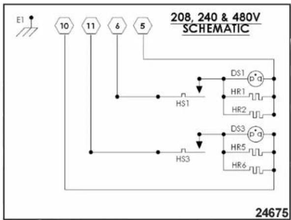
36" SCHEMATIC
1 & 3 PHASE
| 208, 240, & 480 VAC, 1 & 3 PHASE | ||||
| X-Y Y-Z X-Z | TOTAL | |||
| kW PER LINE 5.4 5.4 5.4 16.2 | ||||
| NOMINAL AMPS PER LINE | ||||
| 3-PHASE 1-PHASE | ||||
| XYZ- | ||||
| 208 45.0 45.0 | 45.0 77.9 | |||
| 240 39.0 39.0 | 39.0 67.5 | |||
| 480 19.5 19.5 | 19.5 33.8 | |||
FOR 3-PHASE:
- Connect wire #10 to L1.
- Connect wire #11 to L2.
- Connect wire #5 & #6 to L3.
FOR 1-PHASE:
- Connect wire #5 & #10 to L1.
- Connect wire #6 & #11 to L2.
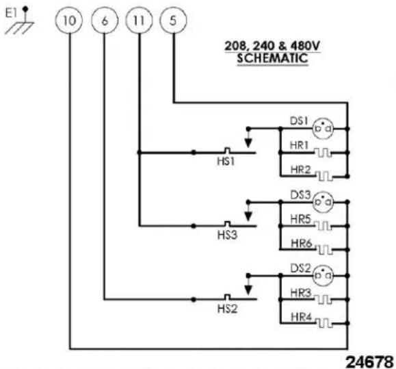
FOR 2-PHASE, 3 WIRE:
- Connect wire #5 & #10 to neutral ("N").
- Connect wire #6 to L1.
- Connect wire #11 to L2.

2 PHASE, 3 WIRE
48" WIRING DIAGRAM
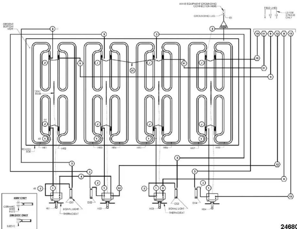
48" WIRING DIAGRAM
Notes:
- For supply connections, use copper wire sized in accordance with the national electrical code and suitable for at least 90°C (194°F).
- Lead marker numbers are the same as lead item numbers unless otherwise specified.
- Wiring to be:
A. 10G,m 532515 - leads 1, 4, 8 - 13, J, J2 and GRD.
B. 18GA., 532518 - leads 2 and 3.
48" SCHEMATIC
1 & 3 PHASE
| 208, 240, & 480 VAC, 1 & 3 PHASE | ||||
| X-Y Y-Z X-Z | TOTAL | |||
| kW PER LINE 10 | 8 5.4 5.4 21.6 | |||
| NOMINAL AMPS PER LINE | ||||
| 3-PHASE 1-PHASE | ||||
| XYZ- | ||||
| 208 67.4 67.4 | 4 45.0 103.8 | |||
| 240 58.5 58.5 | 39.0 90.0 | |||
| 480 29.2 29.2 | 19.5 45.0 | |||
FOR 3-PHASE:
- Connect wire #10 & #11 to L1.
- Connect wire #8, #9 & #13 to L2.
- Connect wire #12 to L3.
FOR 1-PHASE:
- Connect wire #8, #12 & #13 to L1.
- Connect wire #9, #10 & #11 to L2.

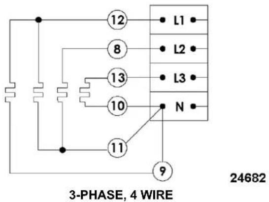
FOR 3-PHASE, 4 WIRE:
- Connect wire #9, #10 & #11 to neutral ("N").
- Connect wire #12 to L1.
- Connect wire #8 to L2.
- Connect wire #13 to L3.
380 & 415V
SCHEMATIC
3-PHASE, 4 WIRE
60" WIRING DIAGRAM

flowchart
graph TD
    A["ORIGUE BOTH TONE H8"] --> B["H1"]
    C["ORIGUE BOTH TONE H9"] --> D["H2"]
    E["HERO/EXT"] --> F["H3"]
    G["INSEQUIPMENT OILING NO CONNECT ON HERE OROUN NO LIO"] --> H["I/O"]
    I["LITOR SPASE ONLY"] --> J["LINE TONBOX FELD LINES"]
    K["LITOR SPASE ONLY"] --> L["JUN TON BOX LEFTBODY FELD LINES"]
    M["LITOR SPASE ONLY"] --> N["LINE TONBOX LEFTBODY FELD LINES"]
    O["HLION 50%"] --> P["H1"]
    Q["HLION 40%"] --> R["H2"]
    S["HLION 30%"] --> T["H3"]
    U["HLION 20%"] --> V["H4"]
    W["HLION 10%"] --> X["H5"]
    Y["HLION 5%"] --> Z["H6"]
    AA["HLION 3%"] --> AB["H7"]
    AC["HLION 2%"] --> AD["H8"]
    AE["HLION 1%"] --> AF["H9"]
    AG["HLION 0%"] --> AH["H10"]
    AI["HLION 0%"] --> AJ["H11"]
    AK["HLION 0%"] --> AL["H12"]
    AM["HLION 0%"] --> AN["H13"]
    AO["HLION 0%"] --> AP["H14"]
    AQ["HLION 0%"] --> AR["H15"]
    AS["HLION 0%"] --> AT["H16"]
    AU["HLION 0%"] --> AV["H17"]
    AW["HLION 0%"] --> AX["H18"]
    AY["HLION 0%"] --> AZ["H19"]
    BA["HLION 0%"] --> BB["H20"]
    BC["HLION 0%"] --> BD["H21"]
    BE["HLION 0%"] --> BF["H22"]
    BG["HLION 0%"] --> BH["H23"]
    BI["HLION 0%"] --> BJ["H24"]
    BK["HLION 0%"] --> BL["H25"]
    BM["HLION 0%"] --> BN["H26"]
    BO["HLION 0%"] --> BP["H27"]
    BQ["HLION 0%"] --> BR["H28"]
    BS["HLION 0%"] --> BT["H29"]
    BU["HLION 0%"] --> BV["H30"]
    BW["HLION 0%"] --> BX["H31"]
    BY["HLION 0%"] --> BZ["H32"]
    CA["HLION 0%"] --> CB["H33"]
    CC["HLION 0%"] --> CD["H34"]
    CE["HLION 0%"] --> CF["H35"]
    DG["HLION 0%"] --> DH["H36"]
    DI["HLION 0%"] --> DJ["H37"]
    DK["HLION 0%"] --> DL["H38"]
    DV["HLION 0%"] --> DW["H39"]
    DX["HLION 0%"] --> DXB["H40"]
NOTES:

flowchart
graph TD
    A["CERAMIC WIRE NUTS"] --> B["480V ONLY"]
    B --> C["208/240V ONLY"]
    C --> D["SLEEVE"]
    D --> E["12"]
    E --> F["8"]
    F --> G["17"]
    G --> H["10"]
    H --> I["E2"]
    I --> J["JUNCTION BOX RIGHT BODY"]
    J --> K["DS1 HR1 HR2"]
    K --> L["HS1"]
    L --> M["DS3 HR5 HR6"]
    M --> N["HS3"]
    N --> O["DS2 HR3 HR4"]
    O --> P["HS2"]
    P --> Q["18"]
    Q --> R["15"]
    R --> S["16"]
    S --> T["HS4"]
    T --> U["DS4 HR7 HR8"]
    U --> V["HS5"]
    V --> W["HR9 HR10"]
    W --> X["JUNCTION BOX LEFT BODY"]
    X --> Y["DS5 HR9 HR10"]
    Y --> Z["HS5"]
    Z --> AA["208, 240 & 480V SCHEMAIC"]
- FOR SUPPLY CONNECTIONS USE COPPER WIRE SIZED IN ACCORDANCE WITH THE NATIONAL ELECTRICAL CODE AND SUITABLE FOR AT LEAST 90 °C (194 °F).
2 SERVICING ONLY EACH HALF OF THIS GRIDDLE IS WIRED SEPERATELY AND TERMINATES IN ITS OWN JUNCTION BOX. EACH JUNCTION BOX REQUIRES A SEPERATE FUSED BRANCH CIRCUIT POWER SUPPLY AS THE GRIDDLE IS NOT FUSED. BOTH POWER SOURCES HAVE TO BE DISCONNECTED BEFORE SERVICING THE DEVICE. - LEAD MARKER NUMBERS ARE THE SAME AS LEAD ITEM NUMBERS UNLESS OTHERWISE SPECIFIED.
- WIRING TO BE: 10G., 532515 - LEADS 1, 4, 8, 10, 12, 15-18, J, J2 and GRD 18GA., 532518 - LEADS 2 and 3

HEG60E
60" ELECTRIC GRIDDLE
DERIVED FROM 944440 REV C
AI5318
HEG60E 60" ELECTRIC GRIDDLE
60" SCHEMATIC
1 & 3 PHASE
| 208, 240, & 480 VAC, 1 & 3 PHASE | |||||
| X-Y Y-Z X-Z TOTAL | |||||
| kW PER LINE | LEFT 5.4 0 5.4 | 10.8 | |||
| RIGHT 5.4 5.4 5 | 4 16.2 | ||||
| NOMINAL AMPS PER LINE | |||||
| 3-PHASE 1-PHASE | |||||
| X | Y | Z | - | ||
| NOMINAL AMPS PER LINE | |||||
| 3-PHASE 1-PHASE | |||||
| 208 | LEFT 45.0 22.5 | 22.5 51.9 | |||
| RIGHT 45.0 45.0 | 45.0 77.9 | ||||
| 240 | LEFT 39.0 19.5 | 19.5 45.0 | |||
| RIGHT 39.0 39.0 | 39.0 67.5 | ||||
| 480 | LEFT 19.5 9.7 | 9.7 22.5 | |||
| RIGHT 19.5 19.5 | 19.5 33.8 | ||||
LEFT JUNCTION BOX PHASE WIRING:
FOR 3-PHASE:
- Connect wire #18 to L1.
- Connect wire #16 to L2.
- Connect wire #15 to L3.
FOR 1-PHASE:
- Connect wire #15 & #16 to L1.
- Connect wire #18 to L2.
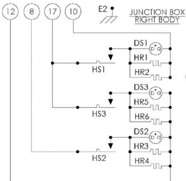
RIGHT JUNCTION BOX PHASE WIRING:
FOR 3-PHASE:
- Connect wire #8 & #10 to L1.
- Connect wire #17 to L2.
- Connect wire #12 to L3.
FOR 1-PHASE:
- Connect wire #10 & #12 to L1.
- Connect wire #8 & #17 to L2.
LEFT JUNCTION BOX PHASE WIRING
- Connect wire #18 to neutral (N).
- Connect wire #16 to L1.
- Connect wire #15 to L2.
RIGHT JUNCTION BOX PHASE WIRING
- Connect wire #8 & #10 to neutral (N).
- Connect wire #12 to L1.
- Connect wire #17 to L2.
380 & 415V SCHEMATIC
2-PHASE, 3 WIRE
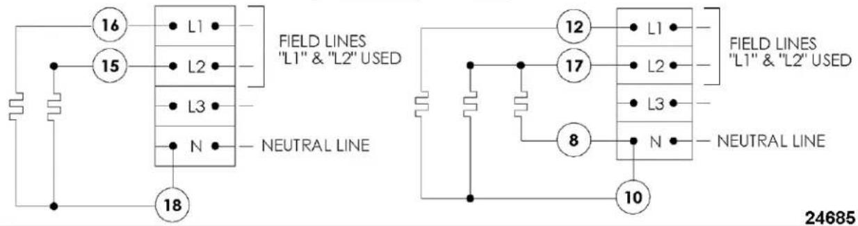
2-PHASE, 3 WIRE
72" WIRING DIAGRAM

flowchart
graph TD
    A["Power Supply"] --> B["Module 1"]
    B --> C["Module 2"]
    C --> D["Module 3"]
    D --> E["Module 4"]
    E --> F["Module 5"]
    F --> G["Module 6"]
    G --> H["Module 7"]
    H --> I["Module 8"]
    I --> J["Module 9"]
    J --> K["Module 10"]
    K --> L["Output"]

    subgraph Module_1
        M1["MASS EQUIPMENT GROUNDING CONNECTION HERE"]
        M2["GROUNDING UIC"]
        M3["THRESHING LINE"]
        M4["THRESHING LINE"]
        M5["THRESHING LINE"]
        M6["THRESHING LINE"]
        M7["THRESHING LINE"]
        M8["THRESHING LINE"]
    end

    subgraph Module_2
        N1["INJUNCTION ON"]
        N2["INJUNCTION ON"]
        N3["INJUNCTION ON"]
        N4["INJUNCTION ON"]
        N5["INJUNCTION ON"]
        N6["INJUNCTION ON"]
        N7["INJUNCTION ON"]
        N8["INJUNCTION ON"]
    end

    subgraph Module_3
        O1["JUNCTION ON"]
        O2["JUNCTION ON"]
        O3["JUNCTION ON"]
        O4["JUNCTION ON"]
        O5["JUNCTION ON"]
        O6["JUNCTION ON"]
        O7["JUNCTION ON"]
        O8["JUNCTION ON"]
    end

    subgraph Module_4
        P1["JUNCTION ON"]
        P2["JUNCTION ON"]
        P3["JUNCTION ON"]
        P4["JUNCTION ON"]
        P5["JUNCTION ON"]
        P6["JUNCTION ON"]
        P7["JUNCTION ON"]
    end

    subgraph Module_5
        Q1["JUNCTION ON"]
        Q2["JUNCTION ON"]
        Q3["JUNCTION ON"]
        Q4["JUNCTION ON"]
        Q5["JUNCTION ON"]
        Q6["JUNCTION ON"]
    end

    subgraph Module_6
        R1["JUNCTION ON"]
        R2["JUNCTION ON"]
        R3["JUNCTION ON"]
        R4["JUNCTION ON"]
        R5["JUNCTION ON"]
    end

    subgraph Module_7
        S1["JUNCTION ON"]
        S2["JUNCTION ON"]
        S3["JUNCTION ON"]
        S4["JUNCTION ON"]
        S5["JUNCTION ON"]
    end

    subgraph Module_8
        T1["JUNCTION ON"]
        T2["JUNCTION ON"]
        T3["JUNCTION ON"]
        T4["JUNCTION ON"]
    end

    subgraph Module_9
        U1["JUNCTION ON"]
        U2["JUNCTION ON"]
        U3["JUNCTION ON"]
        U4["JUNCTION ON"]
    end

    subgraph Module_10
        V1["JUNCTION ON"]
        V2["JUNCTION ON"]
        V3["JUNCTION ON"]
        V4["JUNCTION ON"]
    end

    subgraph Module_11
        W1["JUNCTION ON"]
        W2["JUNCTION ON"]
        W3["JUNCTION ON"]
        W4["JUNCTION ON"]
    end

    subgraph Module_12
        X1["JUNCTION ON"]
        X2["JUNCTION ON"]
        X3["JUNCTION ON"]
        X4["JUNCTION ON"]
    end

    subgraph Module_13
        Y1["JUNCTION ON"]
        Y2["JUNCTION ON"]
        Y3["JUNCTION ON"]
        Y4["JUNCTION ON"]
    end

    subgraph Module_14
        Z1["JUNCTION ON"]
        Z2["JUNCTION ON"]
        Z3["JUNCTION ON"]
        Z4["JUNCTION ON"]
    end

    subgraph Module_15
        AA1["JUNCTION ON"]
        AA2["JUNCTION ON"]
        AA3["JUNCTION ON"]
        AA4["JUNCTION ON"]
    end

    subgraph Module_16
        AB1["JUNCTION ON"]
        AB2["JUNCTION ON"]
        AB3["JUNCTION ON"]
        AB4["JUNCTION ON"]
    end

    subgraph Module_17
        AC1["JUNCTION ON"]
        AC2["JUNCTION ON"]
        AC3["JUNCTION ON"]
        AC4["JUNCTION ON"]
    end

    subgraph Module_18
        AD1["JUNCTION ON"]
        AD2["JUNCTION ON"]
        AD3["JUNCTION ON"]
        AD4["JUNCTION ON"]
    end

    subgraph Module_19
        AE1["JUNCTION ON"]
        AE2["JUNCTION ON"]
        AE3["JUNCTION ON"]
        AE4["JUNCTION ON"]
    end

    subgraph Module_20
        AF1["JUNCTION ON"]
        AF2["JUNCTION ON"]
        AF3["JUNCTION ON"]
        AF4["JUNCTION ON"]
    end

    subgraph Module_21
        AG1["JUNCTION ON"]
        AG2["JUNCTION ON"]
        AG3["JUNCTION ON"]
        AG4["JUNCTION ON"]
    end

    subgraph Module_22
        AH1["JUNCTION ON"]
        AH2["JUNCTION ON"]
        AH3["JUNCTION ON"]
        AH4["JUNCTION ON"]
    end

    subgraph Module_23
        AI1["JUNCTION ON"]
        AI2["JUNCTION ON"]
        AI3["JUNCTION ON"]
        AI4["JUNCTION ON"]
    end

    subgraph Module_24
        AJ1["JUNCTION ON"]
        AJ2["JUNCTION ON"]
        AJ3["JUNCTION ON"]
        AJ4["JUNCTION ON"]
    end

    subgraph Module_25
        AK1["JUNCTION ON"]
        AK2["JUNCTION ON"]
        AK3["JUNCTION ON"]
        AK4["JUNCTION ON"]
    end

    subgraph Module_26
        AL1["JUNCTION ON"]
        AL2["JUNCTION ON"]
        AL3["JUNCTION ON"]
        AL4["JUNCTION ON"]
    end

    subgraph Module_27
        AM1["JUNCTION ON"]
        AM2["JUNCTION ON"]
        AM3["JUNCTION ON"]
        AM4["JUNCTION ON"]
    end

    subgraph Module_28
        AN1["JUNCTION ON"]
        AN2["JUNCTION ON"]
        AN3["JUNCTION ON"]
        AN4["JUNCTION ON"]
    end

    subgraph Module_29
        AO1["JUNCTION ON"]
        AO2["JUNCTION ON"]
        AO3["JUNCTION ON"]
        AO4["JUNCTION ON"]
72" WIRING DIAGRAM
Notes:
- For supply connections, use copper wire sized in accordance with the national electrical code and suitable for at least 90^ C ( 194^ F).
2. SERVICING ONLY
Each half of this griddle is wired separately and terminates in its own junction box. Each junction box requires a separate fused branch circuit power supply as the griddle is not fused. Both power sources have to be disconnected before servicing the device.
-
Lead marker numbers are the same as lead item numbers unless otherwise specified.
-
Wiring to be:
A. 10G,m 532515 - leads 1, 4, 8, 10, 11, 15 - 19, J, J2 and GRD.
B. 18GA., 532518 - leads 2 and 3.
72" SCHEMATIC
1 & 3 PHASE
| 208, 240, & 480 VAC, 1 & 3 PHASE | |||||
| X-Y Y-Z X-Z TOTAL | |||||
| kW PER LINE | LEFT 5.4 5.4 5.4 16.2 | ||||
| RIGHT 5.4 5.4 5.4 16.2 | |||||
| NOMINAL AMPS PER LINE | |||||
| 3-PHASE 1-PHASE | |||||
| XYZ- | |||||
| 208 | LEFT 45.0 45.0 | 45.0 77.9 | |||
| RIGHT 45.0 45.0 | 45.0 77.9 | ||||
| 240 | LEFT 39.0 39.0 | 39.0 67.5 | |||
| RIGHT 39.0 39.0 | 39.0 67.5 | ||||
| 480 | LEFT 19.5 19.5 | 19.5 33.8 | |||
| RIGHT 19.5 19.5 | 19.5 33.8 | ||||
LEFT JUNCTION BOX PHASE WIRING:
FOR 3-PHASE:
- Connect wire #16 & #11 to L1.
- Connect wire #15 to L2.
- Connect wire #18 to L3.
FOR 1-PHASE:
- Connect wire #11 & #18 to L1.
- Connect wire #16 & #15 to L2.
RIGHT JUNCTION BOX PHASE WIRING:
FOR 3-PHASE:
- Connect wire #8 & #10 to L1.
- Connect wire #17 to L2.
- Connect wire #19 to L3.
FOR 1-PHASE:
- Connect wire #10 & #19 to L1.
- Connect wire #8 & #17 to L2.

flowchart
graph TD
    A["18"] --> B["HS4"]
    C["16"] --> B
    D["15"] --> B
    E["11"] --> B
    F["E2"] --> G["HS4"]
    G --> H["DS4"]
    G --> I["HR7"]
    G --> J["HR8"]
    K["HS6"] --> L["DS6"]
    K --> M["HR11"]
    K --> N["HR12"]
    O["HS5"] --> P["DS5"]
    O --> Q["HR9"]
    O --> R["HR10"]

flowchart
graph TD
    A["19"] --> B["8"]
    B --> C["17"]
    C --> D["10"]
    D --> E["E1"]
    E --> F["HS1"]
    F --> G["DS1"]
    G --> H["HR1"]
    H --> I["HR2"]
    I --> J["HS3"]
    J --> K["DS3"]
    K --> L["HR5"]
    L --> M["HR6"]
    M --> N["HS2"]
    N --> O["DS2"]
    O --> P["HR3"]
    P --> Q["HR4"]
    Q --> R["24687"]
1 & 3 PHASE
2 PHASE, 3 WIRE
| 220/380 & 240/415 VAC. 2-PHASE, 3 WIRE | ||||
| L1-N L2-N L3-N | ||||
| kW PER LINE | LEFT 5.4 10.8 0.0 | |||
| RIGHT 5.4 10.8 0.0 | ||||
| NOMINAL AMPS PER LINE | ||||||
| L1 L2 L3 | N TOTAL kW | |||||
| 220/380 | LEFT 6.9 6.9 | 0.0 4.6 13.6 | ||||
| RIGHT 6.9 6.9 | 0.0 4.6 13.6 | |||||
| 240/415 | LEFT 7.5 7.5 | 0.0 5.0 16.2 | ||||
| RIGHT 7.5 7.5 | 0.0 5.0 16.2 | |||||
LEFT JUNCTION BOX PHASE WIRING
- Connect wire #11 & #18 to neutral (N).
- Connect wire #16 to L1.
- Connect wire #15 to L2.
RIGHT JUNCTION BOX PHASE WIRING
- Connect wire #19 & #10 to neutral (N).
- Connect wire #8 to L1.
- Connect wire #17 to L2.
380 & 415V SCHEMATIC
2-PHASE, 3 WIRE


2-PHASE, 3 WIRE
TROUBLESHOOTING
TROUBLESHOOTING
| Troubleshooting Guide | |
| PROBLEM POSSIBLE CAUSES | |
| Heat does not come on when the temperature controller is turned on. | 1. Main power supply disconnected.2. Problem with thermostats. Refer to THERMOSTAT REPLACEMENT.3. Problem with heating elements. Refer to HEATING ELEMENT REPLACEMENT. |
| Fat appears to smoke excessively. | 1. Temperature set too high.2. Moisture in food may be turning into steam. |
| Food sticks to griddle or burned around edges or contain dark specs. | 1. Temperature set too high.2. Griddle surface requires cleaning and/or seasoning.3. Surface under food not covered with enough cooking oil. |
| Food under-cooked inside. | 1. Temperature set too low.2. Food not cooked for long enough time. |
| Food tastes greasy or has objectionable off-flavor. | 1. Food itself may have off-flavor.2. Food stored improperly before cooking.3. Too much griddle fat used.4. Temperature set too low. |
| Noticeable build-up of gum on griddle. | 1. Temperature set too high.2. Griddle surface needs cleaning and/or seasoning.3. Too much griddle fat used. |
| Griddle does not heat. (Indicator light does not glow). | 1. No power to the machine. Circuit breaker tripped.2. Thermostat inoperative. Refer to THERMOSTAT REPLACEMENT. |
| Griddle does not heat. (Indicator light glows). | Heating element(s) inoperative. Refer to HEATING ELEMENT REPLACEMENT. |
| Hot and cold spots controlled by the same thermostat. | Uneven loading patterns.Heating element(s) not clamped tight to griddle plate. Refer to HEATING ELEMENT REPLACEMENT.Different voltage heating elements.Heating elements inoperative. Refer to HEATING ELEMENT REPLACEMENT.Air drafts on griddle plate. |
| Too hot in area controlled by the same thermostat. | 1. Incorrect voltage supply.2. Thermostat bulb not clamped tight to griddle plate.Refer toCAPILLARY BULB INSTALLATION.3. Thermostat not calibrated correctly. Refer toTHERMOSTAT CALIBRATION PROCEDURES. |
| Too cold in area controlled by the same thermostat. | 1. Incorrect voltage supply.2. Thermostat not calibrated correctly. Refer toTHERMOSTAT CALIBRATION PROCEDURES. |


- HEG / RRE / WEG Series Griddle
- TABLE OF CONTENTS
- SERVICE UPDATES 3
- GENERAL 4
- REMOVAL AND REPLACEMENT OF PARTS 5
- SERVICE PROCEDURES AND ADJUSTMENTS 9
- GENERAL
- INTRODUCTION
- INSTALLATION
- CLEANING PROCEDURES
- TOOLS AND TEST EQUIPMENT
- Tools Required
- Special
- LUBRICATION
- OPERATING CONTROLS
- Thermostat
- Indicator Light
- REMOVAL AND REPLACEMENT OF PARTS
- GRIDDLE SERVICE POSITION
- WARNING
- NOTICE
- HEATING ELEMENT REPLACEMENT
- THERMOSTAT REPLACEMENT
- Thermostat Control Removal
- Thermostat Control Installation
- Capillary Tube Installation
- SERVICE PROCEDURES AND ADJUSTMENTS
- THERMOSTAT CALIBRATION PROCEDURES
- TESTING VOLTAGE TO HEATER(S)
- Notes:
- 24" SCHEMATIC
- FOR 3-PHASE:
- FOR 1-PHASE:
- FOR 2-PHASE, 3 WIRE:
- 36" SCHEMATIC
- & 3 PHASE
- 48" SCHEMATIC
- FOR 3-PHASE, 4 WIRE:
- 60" SCHEMATIC
- LEFT JUNCTION BOX PHASE WIRING:
- RIGHT JUNCTION BOX PHASE WIRING:
- LEFT JUNCTION BOX PHASE WIRING
- RIGHT JUNCTION BOX PHASE WIRING
- SERVICING ONLY
- 72" SCHEMATIC
- TROUBLESHOOTING
Brand : Vulcan
Model : HEG36E
Category : Griddle