
DB7404 - Snow blower Cotech - Free user manual and instructions
Find the device manual for free DB7404 Cotech in PDF.


| Product Type | Snow blower |
| Brand | Cotech |
| Model | DB7404 |
| Type | One-stage |
| Clearing Width | 530 mm |
| Max Snow Depth | Approximately 250 mm |
| Discharge Range | Approximately 6 m |
| Engine Displacement | 123 cc |
| Engine Power | 4 HP |
| Fuel Type | Unleaded petrol (95-98 octane) |
| Fuel Tank Capacity | 2.1 L |
| Oil Capacity | 600 ml |
| Oil Type | SAE 5W-30 4-stroke engine oil (SG/SF) |
| Chute Rotation | 180° swivel |
| Discharge Angle Adjustment | 70° |
| Wheel Type | Pneumatic rubber, diameter 190 mm |
| Sound Pressure Level | 86 dB(A) (K=1.5 dB(A)) |
| Sound Power Level | 97 dB(A) (K=1.5 dB(A)) |
| Vibration Level | 15.0 m/s² (K=1.5 m/s²) |
| Weight | 40 kg |
| Ignition | Key start |
| Feed Screw | Rubber blade (replaceable) |
| Shave Blade | Adjustable and replaceable |
| Drive Belt | Replaceable |
| Safety Features | Ignition key, clutch lever, safety guards |
Frequently Asked Questions - DB7404 Cotech
User questions about DB7404 Cotech
0 question about this device. Answer the ones you know or ask your own.
Ask a new question about this device
Download the instructions for your Snow blower in PDF format for free! Find your manual DB7404 - Cotech and take your electronic device back in hand. On this page are published all the documents necessary for the use of your device. DB7404 by Cotech.
USER MANUAL DB7404 Cotech
Read the entire instruction manual carefully and make sure that you fully understand it before you use the equipment. Keep the manual for future reference.
Viktig information:
natural_image
Line drawing of a lawn mower with handle and wheels (no text or symbols)ART.NO MODEL
31-4818 DB7404
Ver. 201210
Original instructions
Bruksanvisning i original
Please read the entire instruction manual before use and save it for future reference. We reserve the right for any errors in text or images and for making any necessary technical changes to this document. If you should have any questions concerning technical problems please contact our Customer Services.
Safety


STOP




Read the entire instruction manual before use.
Use ear defenders.
Wear eye protection.
Danger – rotating feed screw.
Beware of flying objects. Make sure on-lookers are kept at a safe distance.
Never touch any of the machine's moving parts until they have stopped completely, the machine has been turned off and the ignition key has been removed.
Never insert your hands into the discharge chute.
Keep unauthorised persons a safe distance away from the machine.
Danger - Petrol is highly flammable. Let the machine cool for at least 2 minutes before refueling.
Never start the machine indoors or in a poorly ventilated area. The engine's exhaust contains deadly carbon monoxide.
General safety precautions
- Read carefully through the instructions and inform yourself about all controls and functions and how to correctly use the snow blower.
- Never let children or others who do not have the adequate knowledge of these instructions use the snow blower. Local ordinances can have restrictions regarding the user's age.
- Never use the machine in the vicinity of others, especially children or animals.
- Remember the user/driver is always ultimately responsible for accidents caused by use of the product.
- Be careful of falling or slipping while the snow blower is in reverse.
- Never use the snow blower whilst under the influence of drugs, alcohol or medicine. Do not use the product if you are tired or sick.
- This product may only be repaired by qualified staff and only using original parts.
- Never use accessories not approved for use by the manufacturer or the retailer where the product was purchased.
Safety precautions during use
- Make sure to keep hands and feet away from rotating parts. Avoid the discharge chute.
- Certain engine parts will become very hot during use. Risk for burn injuries.
- The snow blower cannot be used for any other purpose than for removing snow.
- Be careful when using on gravel paths, pavement and roads. Be attentive for possible hazards and nearby traffic. Avoid steep inclines.
- Never point the discharge chute towards public roads or traffic.
- Stop the engine immediately if you have struck a foreign object. Inspect the machine carefully after such an incident. Do not reuse the snow blower until any possible damage has been repaired.
- If the snow blower begins to vibrate abnormally, turn off the engine immediately and find the cause. Vibrations are normally a sign of problems.
- Existing safety features may not be disconnected or made inoperative.
- Never use the snow blower in the vicinity of fences, cars, windows, inclines, etc. without properly adjusting the discharge chute.
• Always keep children away from areas to be cleared of snow. - Never overload the blower by driving it too fast.
- Be very careful when reversing. Always look behind you for possible obstacles.
- Never point the chute towards onlookers. Never let anyone stand in front of the snow blower.
- Never use the snow blower in conditions of inadequate visibility or improper lighting.
• Make sure you are steadily balanced and have a firm grip on the handles while using the snow blower. - Never use the snow blower on the roof.
Pre-operational precautions
- Make sure that the area being cleared is free from loose and foreign objects.
• Disengage all controls before starting the engine. - Make sure that the controls are easily manoeuvrable and that they return to their original position when released.
- Pre-plan the area to be cleared in order to avoid personal or property damage by flying objects.
- Never use the snow blower without proper clothing. Use appropriate footwear with solid traction especially in slippery conditions.
- Under no circumstances may maintenance and service be performed when the engine is on (if not otherwise instructed by the instruction manual).
• Always use safety glasses or a visor when operating, servicing or carrying out maintenance. - Let the snow blower adjust to outdoor temperatures before using.
Fuelling precautions
Note: Petrol is highly flammable.
- Use 95 or 98 octane unleaded petrol.
- Store the fuel in a container that is suitable for petrol.
• Always fill the container outdoors and do not smoke while filling. - Do not overfill! The fuel level should be a few centimetres from full.
- Fill with fuel before starting the engine. Never open the fuel cap for filling when the engine is running or when warm.
- Replace the fuel cap securely and wipe off any excess fuel.
Controls and functions

- Shave blade
- Rubber feed screw
- Chute
- Chute directional handle
- Fuel cap
- Primer
-
Ignition
-
Starter handle
- Feed screw clutch lever
- Oil drain screw
- Dipstick/oil fill
- Muffler
- Spark plug/spark plug cable
- Choke
Installation
Contents
- Snow blower
- Chute with lock ring
- Spark plug spanner
• 2 ignition/safety keys - Instruction manual
Feed screw clutch lever and wire

natural_image
Two views of a lawn mower with labeled parts and mechanical components (no text or symbols present)- Pull up the handle and tighten the two wing nuts.
natural_image
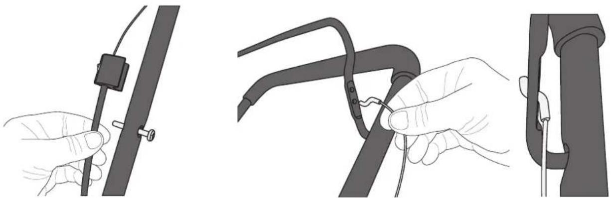
Illustration of three different cable or cable connector assemblies with hands and connectors (no text or symbols)- Remove the wire bracket on the handle and pull up the wire sleeve a little to make it easier to attach the wire to the clutch lever.
- Connect the wire to the bottom hole in the clutch lever. Screw the wire bracket back on.
Chute

natural_image
Technical line drawing of a mechanical component with curved and rectangular features (no text or symbols)-
Make sure the chute's metal position lock sits securely in its catch.
-
Hold the chute in place and put on the lock ring.

natural_image
Illustration of hands adjusting a black athletic shoe component (no text or symbols visible)
natural_image
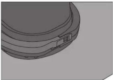
Mechanical component diagram showing a curved arm and circular base with an arrow indicating rotation (no text or symbols)- Secure the snap lock on the lock ring.
natural_image
3D rendered diagram of a mechanical component with a small attached feature (no text or symbols)
natural_image
Mechanical component diagram showing a lever mechanism with a black arrow indicating direction (no text or symbols present)- Loosen the wing knobs on the chute's hood to set the desired discharge angle. Tighten the wing knobs.
Operation
Oil level checks and refills
Note: The snow blower comes without engine oil. Oil must be filled before using the snow blower. Engine oil capacity is 600 ml.
- Use SAE 5W-30 grade 4-stroke petrol engine oil, service category SG, SF.
- Unscrew the dipstick and fill up with engine oil so that the level is within the recommended markings on the dipstick. Do not overfill!
Handy hint: Ask for help to tilt up the snow blower to make oil filling easier.
Note: Do not screw the dipstick cap into place when measuring. Hold it flush against the filling hole to measure.
IMPORTANT:
The oil should be changed after the first 5 hours of use.

natural_image
Technical illustration of a hand adjusting a mechanical component with a spring-loaded bolt (no text or symbols present)
natural_image
Close-up of a hand inserting a small component into a mechanical assembly (no text or symbols visible)Fuelling
Fill with 95 or 98 octane unleaded petrol following the Fuelling precautions procedures described above.
Start
Note: Check the oil and fuel levels before starting.

natural_image
Mechanical assembly diagram showing a tool interacting with a component (no visible text or symbols)- Insert the ignition key completely into the ignition. The key can not be turned, but make sure it is fully inserted.

natural_image
Mechanical component diagram showing directional arrows and labeled parts (no text or symbols)-
Make sure the choke is set to cold start mode. Do not use the choke if the engine is warm.
-
Push the primer bladder 3 times. Cover the vent hole in the centre of the primer bladder when pushing. In cold weather conditions the engine may need to be primed again. If the engine is warm, press the primer once.
- Slowly pull the starter handle until you feel some resistance. Use a quick and powerful motion when pulling the handle to start. Do not release the handle but keep it in position and then return it to its original position.
- Once the engine has been started and is warm, slowly move the choke to its starting position.
- If the engine should stall, restart it with the choke set in the middle position for a short time. Once the engine is stable, slowly return the choke to its original position.
Operation
-
Plan the area of operation and where the snow is to be removed before starting.
-
Clasp the clutch lever and bring it in towards the handle to begin snow clearance and start the feed screw.
-
Release the lever to stop.
Note: Since the snow blower is driven by the feed screw and has no power to the wheels, it may be necessary to lift the handle somewhat to allow the feed screw to have better contact with the surface. Depending on the surface, it may also be necessary to push the machine forward somewhat to achieve forward progress.
- Push the handle down somewhat to lift the feed screw from the surface when backing or stopping.
- To turn off the engine, remove the ignition key.
Care and maintenance
Note: Turn off the engine, remove the ignition key and remove the spark plug cable from the spark plug before servicing, cleaning or maintenance.
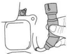
natural_image
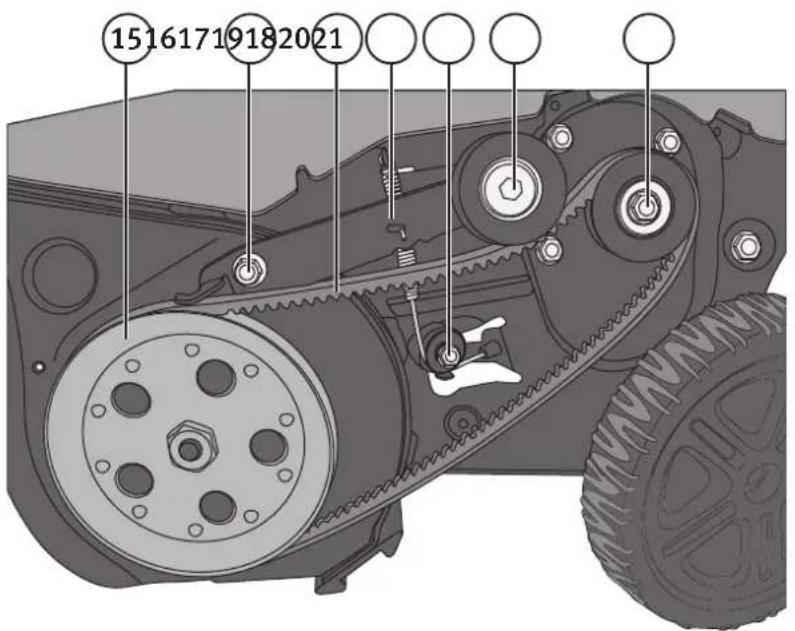
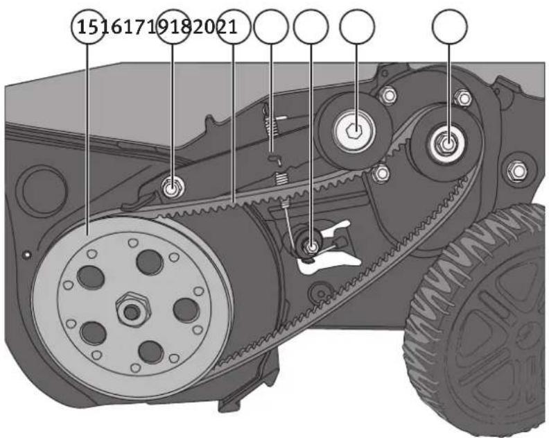
Line drawing of a hand holding a small object next to a mechanical component (no text or symbols)Parts

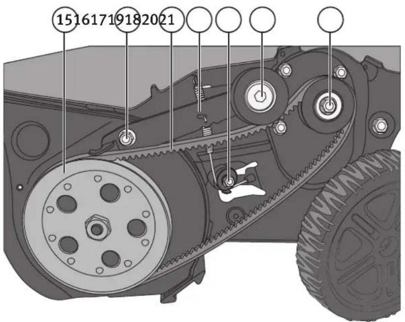
- Feed screw pulley
- Tensioner bolt
- Drive belt
- Tensioner
- Wire guide
- Tensioner wheel
-
Engine pulley
-
Make sure that there are no foreign objects around the muffler.
- Inspect regularly to make sure that all bolts, nuts and screws are tight and that there is no visible damage.
- Regularly check the fuel system for any visible signs of leakage at the tank, fuel cap or fuel lines.
- Never attempt to tamper with or modify the product in any way.
Lubrication
- Lubricate the points where the clutch lever attaches to the handle before every season.
- Lubricate the wire guides and the tensioner bolt before and after every season. Use a few drops of engine oil and/or spray lubricant (e.g. 5–56, WD 40). Do not over-lubricate!
Note: Make sure that no lubricant comes in contact with the drive belt.

natural_image
Diagram of a curved mechanical component with two arrows indicating direction (no text or symbols)Changing oil
Note: Engine oil becomes hot after use. Let the engine cool off a bit before changing the oil.
- Place an appropriate container under the drain plug (10).
- Remove the drain screw and empty the oil.
- Replace the screw and fill with oil. See the Oil level checks and refills section described above.
Spark plug
Note: Let the engine cool before unscrewing and removing the spark plug. Both the spark plug and muffler become very hot after use. Check the spark plug before every season. Change when necessary.
-
Remove the spark plug cable from the spark plug. Do not pull the cable but rather grip the spark plug cap and wiggle it back and forth to loosen it.
-
Use a spark plug spanner to remove it from its socket.
-
Check the electrodes for any visible damage and clean with a steel brush when necessary.
-
Check that the electrode gap is between 0.6–0.8 mm. Special tools for gapping are available for purchase separately.
-
Try to screw the spark plug partway in by hand to make sure the threads catch correctly. Tighten using a spark plug spanner.
-
Washers on the new spark plug must be compressed during installation. Tighten a 12 turn extra after the spark plug is securely in place to compress the washer and create a proper seal.
-
Turn a 14 turn extra if you are using the existing spark plug.

Handy hint: Thread a small piece of PVC hose to the spark plug tip to make it easier to insert and thread into the socket.
Clutch lever wire adjustment
The wire becomes slack after some usage and it may be necessary to adjust it from time to time.
- Unscrew the wire bracket from the handle as previously described under the Installation section.
- Move the wire to the upper hole.
- Screw the wire bracket back on.
- Start the snow blower and check for proper operation.
- If the clutch lever still doesn't work satisfactorily the drive belt should be changed.
Changing the Drive Belt
Disassembly

natural_image
Mechanical component diagram showing a belt drive mechanism with pulleys and mounting holes (no text or symbols)- Remove the protective cover by removing the 4 retaining screws.

natural_image
Illustration of a hand adjusting a mechanical component with a wheel and shaft (no text or symbols visible)- Grab the belt in front of the feed screw's pulley and remove it from the pulley.

natural_image
Close-up of hands operating a mechanical component with a belt and adjustment knob (no visible text or symbols)- Press the tensioner wheel down to release the belt from the belt tension tab which presses against the feed screw's pulley.
Reinstallation
- Press the tensioner wheel down to allow the belt enough room under the belt tension tab to be reinstalled.
- Release the tensioner wheel and re-install the belt in reverse order. Finish by threading the belt to the bottom of the feed screw pulley.
- Adjust the wire by attaching it to the clutch lever's bottom hole and check for proper functioning.
- Move the wire to the upper hole if necessary.
- Replace the protective cover.
Shave blade changing or adjustment
If the wheels, shave blade and feed screw do not contact the surface at the same time, the shave blade should be adjusted and/or the rubber blades need to be changed.
- Place the snow blower on a level surface. The wheels, shave blade and the feed screw should all make contact with the surface at the same time.
- If the shave blade is too high, snow will be discharged out the back, under the blower.
- If the shave blade is too low, it will wear out prematurely and forward propulsion will be adversely affected.
Adjustment
- Empty the fuel tank when the engine is cold. Do the work outside and collect the fuel in an appropriate container. If the fuel is not to be reused, deposit it at the most appropriate recycling centre.
natural_image
Illustration of a firearm with an arrow indicating motion direction (no text or symbols)
natural_image
Diagram of a vehicle chassis with wheels and a motor, showing four upward arrows indicating motion or force direction (no text or symbols present)-
Loosen the 4 screws and adjust the shave blade to the desired position.
-
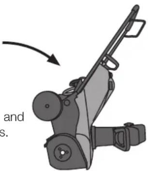
Tilt the blower forward so that the wheels are off the ground and the blower rests on its chassis.
-
Re-tighten the screws securely.
Note: If the blower is tipped back so that the handle touches the ground, there is a risk that engine oil will leak into the engine's combustion chamber and cause starting problems. If this should occur, remove the spark plug and clean it thoroughly. Pull the starter handle several times with the spark plug removed in order to remove any excess oil. Please remember to check the oil level again and add oil if needed. Replace the spark plug and start the engine, which will initially produce smoke in the exhaust. This is completely normal.
Replacement
- Empty the fuel tank when the engine is cold. Do the work outside and collect the fuel in an appropriate container. If the fuel is not to be reused, deposit it at the most appropriate recycling centre.
- Tilt the blower forward so that the wheels are off the ground and the blower rests on its chassis.
- Loosen the 4 screws and remove the shave blade.
- Install the new shave blade so that the wheels, shave blade and the feed screw make contact with an even level surface at the same time.
- Retighten the screws securely.
Changing the rubber feed screw blade
- Loosen the 4 retaining screws and feed screw.
- Replace with a new blade and tighten the retaining bolts securely.

natural_image
Mechanical assembly diagram showing a motor or gear mechanism with no visible text or symbolsEngine service intervals
Follow the hourly or seasonal schedule depending on which occurs first.
| After the first 5 hours. | At every use or after every 5 hours. | At every use or after every 25 hours. | At every use or after every 50 hours. | |
| Check the oil level. • | ||||
| Change oil. • • | ||||
| Check spark plug. • | ||||
| Clear area around muffler. • |
Long-term storage procedures (over a month)
- Empty the fuel tank when the engine is cold. Do the work outside and collect the fuel in an appropriate container. If the fuel is not to be reused, deposit it at the most appropriate recycling centre.
- Start the engine and let it run until it is out of fuel.
- Store the snow blower in a well ventilated area where there are no open flames, sparks or other heat sources present in close vicinity.
Disposal
When it is time to dispose of this product, do so in accordance with local regulations. If you are unsure how to proceed, contact your local authority.
Specifications
Type One-stage
Clearing capacity 530 mm
Max snow depth approximately 250 mm
Discharge range approximately 6 m
Engine 123 cc, 4 HP
Fuel tank capacity 21
Chute 180° swivel
Discharge angle 70° adjustable
Pneumatic rubber tyres, diam 190 mm
Sound pressure level 86 dB(A), uncertainty K=1.5 dB(A)
Sound power level 97 dB(A), uncertainty K=1.5 dB(A)
Vibration value 15.0 m/s ^2 , uncertainty K=1.5 m/s ^2
Weight 40 kg
Troubleshooting guide
| Problem Possible | cause Solution | |
| The engine does not start. | No fuel or the fuel is too old.Clogged fuel line.Ignition key not fully inserted.Spark plug cable not properly connected.Defective spark plug.Engine not adequately primed.Engine is flooded (over-priming). | Empty the tank and refill with new fuel.Clean or replace the fuel lines.Insert the key completely.Securely attach the spark plug wire.Clean the plug and check the electrode gap or change plugs.Press the primer about 3–5 times.Wait at least 10 min. before a restart attempt. |
| The engine runs irregularly. | The engine runs on choke even when warm.Blocked fuel lines or old petrol.Sediment and/or water in the fuel system.The carburettor is maladjusted. | Reset the choke back into place.Clean or replace the fuel lines. Empty the tank and refill with new fuel.Empty the tank and carburettor and refill with new fuel.Contact an authorised service centre. |
| The engine is underpowered. | Spark plug cable loose.Fuel cap's vents blocked. | Fasten the spark plug cable securely to the plugClean the fuel cap and make sure ventilation holes are free. |
| The engine is overheated. | The carburettor is maladjusted. Contact an authorised service centre. | |
| Abnormal vibrations occur. | Loose parts or damaged feed screw. Turn off the engine and disconnect the spark plug wire. Tighten all bolts. Check the feed screw and replace any damaged parts. | |
| The blower doesn't move forward. | The wire and/or shave blade is maladjusted.The drive belt is loose or damaged. | Adjust the wire and/or shave blade.Install the drive belt correctly or replace it if it is damaged. |
| The feed screw continues to rotate despite being disengaged. | The wire is maladjusted. Adjust the wire by moving it to the bottom hole of the clutch lever. | |
| No snow exits the chute. | The chute is clogged.Foreign object/s are preventing the feed screw from rotating.The wire is maladjusted or the drive belt needs changing. | Turn off the engine and disconnect the spark plug wire. Clean out the chute and the area around the feed screw with an appropriate object (e.g. a wooden stick or similar).Clean out the area around the feed screw with an appropriate object (e.g. a wooden stick or similar)Adjust the wire by moving it to the top hole of the clutch lever. |
Enstegs snöslunga 4 hk
ART.NR 31-4818 MODELL DB7404
natural_image
Two views of a lawn mower with mechanical components and circular annotations indicating rotation or repair steps (no text or symbols present)natural_image
Illustration of three hands performing a cable or cable clamp operation (no text or symbols present)natural_image
3D technical illustration of a mechanical component with internal cavities and mounting brackets (no text or symbols)natural_image
Illustration of hands adjusting a black athletic bag on a table (no text or symbols visible)
natural_image
Mechanical component diagram showing a curved arm and circular base with an arrow indicating rotation (no text or symbols)natural_image
3D rendered diagram of a mechanical component with no visible text or symbols
natural_image
Mechanical seat assembly diagram showing a bracket and seat (no text or labels)natural_image
Technical illustration of a hand adjusting a mechanical component with a close-up view of a threaded fastener (no text or symbols present)
natural_image
Hand inserting a component into a mechanical assembly (no text or symbols visible)Fyll på bränsle
natural_image
Mechanical assembly diagram showing a tool interacting with a component (no visible text or symbols)natural_image
Mechanical component diagram showing a lever mechanism with no visible text or symbolsnatural_image
Line drawing of a hand holding a tool next to a mechanical component (no text or symbols)Delar
natural_image
Pure diagram of a curved mechanical component with directional arrows, no text or symbols presentOljebyte
natural_image
Mechanical component diagram showing a wheel with attached components and mounting holes (no text or symbols)natural_image
Illustration of a hand adjusting a mechanical component with a pulley and screw holes (no text or symbols)natural_image
Close-up of hands operating a mechanical component with a belt and adjustment knob (no text or symbols visible)natural_image
Diagram of a firearm with an arrow indicating motion direction (no text or symbols)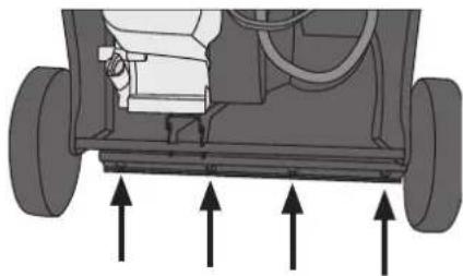
natural_image
Diagram of a vehicle chassis showing front wheel, rear wheels, and internal components with upward arrows indicating motion (no text or symbols)natural_image
Mechanical assembly diagram showing internal components with arrows indicating motion (no text or symbols)Motorns serviceintervall
natural_image
Two views of a lawn mower with mechanical components and close-up insets showing adjustment mechanism (no text or symbols)natural_image
Hand holding a black cable with a small connector, no text or symbols visiblenatural_image
Illustration of a hand holding a cable being inserted into a device (no text or symbols present)natural_image
Technical line drawing of a mechanical component with no visible text or symbols-
Kontroller at metallsperren på utkastet sitter i festet sitt.
-
Hold utkastet på plass og monter låsekragen.

natural_image
Illustration of hands assembling a dark mechanical component (no text or symbols visible)
natural_image
Mechanical component diagram showing a curved arm and lever mechanism (no text or symbols)- Fest kragen med snepplåsen.

natural_image
3D rendered mechanical component with curved surfaces and a small rectangular feature (no text or symbols)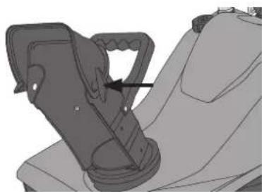
natural_image
Mechanical component diagram showing a lever mechanism with a black arrow indicating direction (no text or symbols present)natural_image
Technical illustration of a mechanical assembly with a hand adjusting a component, alongside a close-up of a spring-loaded component (no text or symbols visible)
natural_image
Line drawing of a hand inserting a component into a mechanical housing (no text or symbols)natural_image
Mechanical assembly diagram showing a hand holding a tool with a clamp and multiple components (no text or labels visible)natural_image
Mechanical component diagram showing a lever mechanism with labeled parts (no text or symbols present)natural_image
Line drawing of a hand holding a tool next to a mechanical component (no text or symbols)Deler
natural_image
Pure diagram of a curved mechanical component with directional arrows, no text or symbols presentOljeskift
natural_image
Mechanical component diagram showing a lever mechanism with wheels and mounting holes (no text or symbols)natural_image
Illustration of a hand adjusting a mechanical component with a wheel and hub (no text or symbols visible)natural_image
Close-up of hands operating a mechanical component with a belt and adjustment knob (no visible text or symbols)natural_image
Mechanical device with lever mechanism and directional arrow (no text or symbols)
natural_image
Diagram of a vehicle chassis with wheels and structural components, showing upward arrows indicating motion direction (no text or symbols present)natural_image
Mechanical assembly diagram showing a motor or gear mechanism with no visible text or symbolsMotorens serviceintervaller
natural_image
Two views of a lawn mower with mechanical components and close-up insets showing adjustment mechanism (no text or symbols)natural_image
Hand holding a cable with a small component inserted, no text or symbols visiblenatural_image
Illustration of a hand holding a cable to connect two components, showing the process (no text or symbols present)natural_image
3D technical illustration of a mechanical component with internal cavities and mounting brackets (no text or symbols)natural_image
Illustration of hands adjusting a black athletic bag on a table (no text or symbols visible)
natural_image
Mechanical component diagram showing a curved arm and circular base with an arrow indicating rotation (no text or symbols)natural_image
3D rendered diagram of a mechanical component with no visible text or symbols
natural_image
Mechanical component diagram showing a belt buckle assembly (no text or symbols)natural_image
Technical illustration of a mechanical assembly with a hand adjusting a component, alongside a close-up of a spring-loaded component (no text or symbols visible)
natural_image
Illustration of a hand inserting a component into a mechanical housing (no text or symbols visible)Polttoaineen lisäys
natural_image
Mechanical assembly diagram showing a tool interacting with a component (no visible text or symbols)natural_image
Mechanical component diagram showing a lever mechanism with directional arrows (no text or symbols)natural_image
Line drawing of a hand holding a tool next to a mechanical component (no text or symbols)Osat
natural_image
Pure diagram of a curved mechanical component with directional arrows, no text or symbols presentÖljynvaihto
natural_image
Mechanical component diagram showing a wheel and belt mechanism (no text or symbols)natural_image
Illustration of a hand adjusting a mechanical component with a circular dial and screw holes (no text or symbols)natural_image
Close-up of hands operating a mechanical component with a belt and adjustment knob (no text or symbols visible)natural_image
Mechanical device with lever and attached components, showing motion direction (no text or symbols)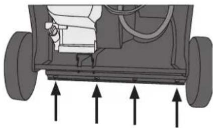
natural_image
Diagram of a vehicle chassis showing front wheel, rear wheels, and internal components with upward arrows indicating motion (no text or symbols)natural_image
Mechanical assembly diagram showing a motor and gear components with no visible text or symbolsDeclaration of Conformity
Machinery directive 2006/42/EC
EMC directive 2004/108/EC
Low voltage directive 2006/95/EC
ISO/DIS 8437:2008 EN
SO 14982:2009 EN 603
35-1:2002
+A11:2004+A1:2004
+A12:2006+A2:2006
+A13:2008+A14:2010
Klas Balkow President
Insjön, Sweden, 2012-10-03
CO TECH®
SVERIGE
KUNDTJÄNST Tel: 0247/445 00
Fax: 0247/445 09
E-post: kundtjanst@clasohlson.se
INTERNET www.clasohlson.se
BREV Clas Ohlson AB, 793 85 INSJÖN
NORGE
KUNDESENTER Tlf.: 23 21 40 00
Faks: 23 21 40 80
E-post: kundesenter@clasohlson.no
INTERNETT www.clasohlson.no
POST
Clas Ohlson AS, Postboks 485 Sentrum, 0105 OSLO
SUOMI
ASIAKASPALVELU Puh.: 020 111 2222
For consumer contact, please visit www.clasohlson.co.uk and click on customer service.
INTERNET www.clasohlson.co.uk
- Safety
- General safety precautions
- Safety precautions during use
- Pre-operational precautions
- Fuelling precautions
- Controls and functions
- Installation
- Contents
- Chute
- Operation
- Oil level checks and refills
- IMPORTANT:
- Fuelling
- Start
- Care and maintenance
- Lubrication
- Changing oil
- Spark plug
- Clutch lever wire adjustment
- Changing the Drive Belt
- Disassembly
- Reinstallation
- Shave blade changing or adjustment
- Adjustment
- Replacement
- Changing the rubber feed screw blade
- Engine service intervals
- Long-term storage procedures (over a month)
- Disposal
- Specifications
- Enstegs snöslunga 4 hk
- Fyll på bränsle
- Delar
- Oljebyte
- Motorns serviceintervall
- Deler
- Oljeskift
- Motorens serviceintervaller
- Polttoaineen lisäys
- Öljynvaihto
- Declaration of Conformity
- CO TECH®
- SVERIGE
- NORGE
- SUOMI
Brand : Cotech
Model : DB7404
Category : Snow blower